EP0627238B1 - Pédomètre - Google Patents
Pédomètre Download PDFInfo
- Publication number
- EP0627238B1 EP0627238B1 EP94301466A EP94301466A EP0627238B1 EP 0627238 B1 EP0627238 B1 EP 0627238B1 EP 94301466 A EP94301466 A EP 94301466A EP 94301466 A EP94301466 A EP 94301466A EP 0627238 B1 EP0627238 B1 EP 0627238B1
- Authority
- EP
- European Patent Office
- Prior art keywords
- pace
- signal
- detected
- walking
- predetermined
- Prior art date
- Legal status (The legal status is an assumption and is not a legal conclusion. Google has not performed a legal analysis and makes no representation as to the accuracy of the status listed.)
- Expired - Lifetime
Links
Images






Classifications
-
- A—HUMAN NECESSITIES
- A63—SPORTS; GAMES; AMUSEMENTS
- A63B—APPARATUS FOR PHYSICAL TRAINING, GYMNASTICS, SWIMMING, CLIMBING, OR FENCING; BALL GAMES; TRAINING EQUIPMENT
- A63B71/00—Games or sports accessories not covered in groups A63B1/00 - A63B69/00
- A63B71/06—Indicating or scoring devices for games or players, or for other sports activities
- A63B71/0686—Timers, rhythm indicators or pacing apparatus using electric or electronic means
-
- Y—GENERAL TAGGING OF NEW TECHNOLOGICAL DEVELOPMENTS; GENERAL TAGGING OF CROSS-SECTIONAL TECHNOLOGIES SPANNING OVER SEVERAL SECTIONS OF THE IPC; TECHNICAL SUBJECTS COVERED BY FORMER USPC CROSS-REFERENCE ART COLLECTIONS [XRACs] AND DIGESTS
- Y10—TECHNICAL SUBJECTS COVERED BY FORMER USPC
- Y10S—TECHNICAL SUBJECTS COVERED BY FORMER USPC CROSS-REFERENCE ART COLLECTIONS [XRACs] AND DIGESTS
- Y10S482/00—Exercise devices
- Y10S482/901—Exercise devices having computer circuitry
-
- Y—GENERAL TAGGING OF NEW TECHNOLOGICAL DEVELOPMENTS; GENERAL TAGGING OF CROSS-SECTIONAL TECHNOLOGIES SPANNING OVER SEVERAL SECTIONS OF THE IPC; TECHNICAL SUBJECTS COVERED BY FORMER USPC CROSS-REFERENCE ART COLLECTIONS [XRACs] AND DIGESTS
- Y10—TECHNICAL SUBJECTS COVERED BY FORMER USPC
- Y10S—TECHNICAL SUBJECTS COVERED BY FORMER USPC CROSS-REFERENCE ART COLLECTIONS [XRACs] AND DIGESTS
- Y10S482/00—Exercise devices
- Y10S482/901—Exercise devices having computer circuitry
- Y10S482/902—Employing specific graphic or video display
Definitions
- the present invention relates to a pace generating device for generating pace signals with predetermined periodicity.
- a pace generating device which has been put to practical use in order to assist exercise is shown in Fig. 12.
- the device generates pace sounds with predetermined periodicity.
- a user inputs a desirable pace thereto by pace data inputting means 108 whilst looking at display means 102.
- This inputted pace data is transformed into a pace signal by a standard clock signal of timing signal generating means 101.
- an inputting means 100 starts the pace outputting, and a pace is outputted by pace outputting means 103 using electronic sounds in accordance with which a user takes exercise.
- Such a conventional pace generating device has a problem in that a user must stop exercising and then operate the inputting means in order to hear the pace sounds to change or check the required pace.
- the pace sounds When the pace sounds are outputted, the pace sounds keeps on being outputted until a user stops exercise and again operates the inputting means. This increases consumption power and makes it difficult to drive the device by an electric battery, which is another problem of a conventional pace generating device.
- a known pace generating device is disclosed in British Patent Publication No. 2121219 in which a shoe is described which measures the user's pace and compares this with a preset pace value. If the measured pace is equal to or greater than the preset pace, a first sound sequence is emitted, while if the measured pace is less than the preset pace, a second sound sequence is emitted. The beat frequency at which the sound sequences are emitted is adjusted based on the measured pace value.
- a further known pace generating device is described in US Patent No. 5164967 which compares the frequency of steps with a preset frequency and emits a sound signal at the preset frequency to guide the user. The device counts a preset number of paces and then visually displays to the user the number of these paces which were made within the predetermined frequency.
- JP 55-134387 Another known pace generating device is described in Japanese Patent Publication No. JP 55-134387 which describes a watch which counts the number of steps over a preset time and compares this to a preset number. A sound is then generated indicating to the user whether the number of paces made in the preset time was equal to or higher or lower than the set number.
- An object of the present invention is to provide a pace generating device which can output a desired pace signal automatically without stopping a user from exercising. Also a pace generating device of which the consumption power is so small as to be installed in a miniature electronic apparatus employing an electrical battery as a driving source.
- the present invention is constituted of a pace generating device comprising:
- timer means for conducting timer operation by output from the pace comparing means and pace outputting prohibition means for prohibiting outputting a pace signal to a pace outputting means by time-up output of the timer means, are provided to the present invention.
- Fig. 1 is a function block diagram showing one example of a typical constitution of the present invention.
- a walking detect means 103 detects walking and then outputs a detected walking signal to a walking pace calculating means 104.
- a standard clock signal outputted by timing signal generating means 101 is inputted to the walking pace calculating means 104. Then the walking pace calculating means 104 measures the period of the detected walking signal and calculates the pace.
- a walking pace storing means 105 stores the walking pace calculated by the walking pace calculating means 104.
- a pace comparing means 106 compares a predetermined pace stored in a pace data storing means 107 with the detected walking pace stored in the walking pace storing means 105.
- the pace comparing means then outputs a pace making instruction signal to a pace signal generating means 109 if the result of the above comparison is out of the predetermined range. Then the pace signal generating means 109 makes a pace signal from a standard clock signal of the timing signal generating means 101 according to a predetermined pace stored in the pace data storing means 107. The pace signal generating means 109 then outputs a pace signal to a pace outputting means 110.
- Fig. 2 is another function block diagram showing one example of a typical constitution of the present invention.
- the pace comparing means 106 compares a predetermined pace stored in the pace data storing means 107 with a detected walking pace stored in the walking pace storing means 105 and outputs a pace making instruction signal to the pace signal generating means 109 if the result of the above comparison is out of the predetermined range.
- the pace comparing means 106 outputs a timer start signal to a timer means 209.
- the timer means 209 receives a timer start signal, then counts a standard clock signal outputted from the timing signal generating means 101, and outputs a time-up signal when the timer operation is finished.
- a pace outputting prohibition means 211 receives the time-up signal and then prohibits inputting a pace signal outputted from the pace signal generating means 109 to the pace outputting means 110.
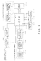
- Fig. 3 is a function block diagram showing a first embodiment of the inventive pace generating device.
- the walking detect circuit 333 comprises a walking sensor circuit 303 for detecting a walking signal, a hysteresis amplifying circuit 304 for amplifying the detected walking signal detected by the walking sensor circuit 303, and a one-shot multivibrator 305 for receiving the amplified detected walking signal.
- the amplified detected walking signal acts as trigger input for enabling the multivibrator to output a signal in accordance with walking being detected.
- An output signal of an oscillating circuit 301 is inputted to a CPU 310 as a standard clock of the CPU 310.
- the output signal is simultaneously divided into a specified frequency by a dividing circuit 302 and then inputted to the CPU 310.
- the CPU 310 conducts a program stored in a ROM 313 in accordance with the standard clock outputted by the oscillating circuit 301.
- An inputting circuit 311 is connected to the CPU 310 and inputs predetermined data, such a pace data, thereto.
- the inputted data is displayed in a display element 314 and besides stored in a RAM 312.
- the pace outputting element 330 comprises a pace signal amplifying circuit 307 and a pace outputting device 308, and outputs a pace signal outputted by the CPU 310.
- Fig. 4 shows a concrete embodiment of a circuit shown in the function block diagram of Fig. 3.
- the walking sensor circuit 303 switches on and off the contacts in accordance with walking, and absorbs chattering of the contacts by means of a resistor R, a condenser C, and a schmitt trigger inverter 304.
- a detected walking signal is inputted to a one-shot multivibrator 305 and then a one-shot pulse of a fixed pulse width is obtained.
- the one-shot multivibrator 305 is of non-retriggerable type which outputs a signal of a fixed pulse width when a signal is inputted to trigger input and ignores retrigger input during pulse output.
- This signal of a fixed pulse width is inputted to an input terminal IN1 of the CPU 310.
- the CPU 310 outputs a buzzer signal in accordance with a fixed pace signal from OUT1.
- the buzzer signal is amplified by counter generating voltage of a coil L in the pace signal amplifying circuit 307.
- the pace outputting element 308 is a piezoelectric buzzer, which is driven by the pace signal amplified by the pace signal amplified by the pace signal amplifying circuit 307.
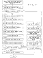
- Fig. 9 is a flow chart showing an operation procedure of Fig. 3.
- Fig. 9 is a flow chart showing an operation procedure of Fig. 3.
- a signal accorded with a walking signal detected by the walking detect circuit 333 is inputted to the input terminal IN1 of the CPU 310, one is added to a walking pace counter in the RAM 312 at either a rising edge or a falling edge of the signal (S100). Then, in this step, the CPU judges whether the input signal is the first input or the second one.
- the CPU waits for a next signal to be inputted because it cannot measure the period of the inputted signal (S101).
- the CPU moves on to period measurement of the input signal and clears the contents of the walking pace counter in the RAM 312 for next measurement (S102).
- the CPU 310 receives the standard clock signal of the timing signal generating circuit 331 and then counts time. The content of counting time is read from a walking pace measuring counter in the RAM 312 (S103).
- the above calculated walking pace is compared with a desirable pace inputted in advance and stored in the RAM 312.
- a permissible range of the difference between the walking pace and the predetermined pace has been determined beforehand.
- the predetermined pace data is 120 (STEP/MIN)
- the detected and calculated walking pace data is 100 (STEP/MIN)
- the permissible range of the difference between both paces is ⁇ 5 (STEP/MIN).
- the difference between both paces is 20 (STEP/MIN), which is out of the range (S108, S109, S110).
- the CPU doesn't prepare for generating a pace signal (S111). If the difference between both paces is out of the range, the CPU moves on to prepare for making a pace signal.
- the pace signal is made by receiving a standard clock signal of 256 Hz, thereby enabling the CPU 310 to be interrupted at a frequency of 256 Hz (S112).
- the pace signal is made by counting the standard clock signal of 256 Hz.
- Interrupting signals of 256 Hz are counted, and when they amount to the CD, then they complete a signal period for outputting a desirable predetermined pace (S113, S114).
- This CD is stored in a pace signal counter in the RAM 312 (S115).
- the CPU 310 outputs a buzzer signal "H” from an output terminal OUT1 to the pace signal amplifying circuit.
- a piezoelectric buzzer PZ receives this "H” signal and then outputs sounds (S116).
- a standard clock signal of 32 Hz is allowed to interrupt the CPU 310 in order to determine the length of the sound.
- CPU 310 counts 1 clock time of the 32 Hz signal.
- a buzzer signal "L” is outputted from an output terminal OUT1 of the CPU 310. In other words, buzzer sound is outputted for 31.25 milli-SEC (S117).
- Fig. 10 is a flow chart showing a procedure for making a pace signal.
- the operation is started by the 256 Hz interrupting signal.
- the counting data CD expressed as the formula (3) is stored in the pace signal counter in the RAM 312 and one is subtracted from the content of the counting data CD every time a 256 Hz signal interrupts (S200).
- the counting value CD is newly calculated from a desirable predetermined pace with a formula (3) and then stored (S201, S202, S203, S204).
- a buzzer signal "H" is newly outputted from an OUT1 terminal of the CPU 310 to the pace signal amplifying circuit 307.
- Fig. 11 is a flow chart showing a second embodiment of the inventive pace generating device.
- the operating procedure of a walking pace calculating means 104 shown in Fig. 2 is explained as a modification of the first embodiment's procedural steps (S300 - S310).
- a timer starts to operate. If the timer is already operated, data is not set to a prohibition timer (S312). On the other hand, if the timer is not operated yet, time data of the timer is set to the prohibition timer counter.
- the prohibition timer is subtracted every interruption of a standard clock of 1 Hz. In this embodiment, time of the timer is 30 seconds (S313).
- a pace signal is generated using the 256 Hz standard clock, thereby allowing the CPU 310 (S314) to be interrupted.
- the desirable predetermined pace is read out from the RAM 312 which stores the pace therein (S315).
- a counting value is calculated for outputting a predetermined pace with the formula (3) shown in the first embodiment.
- a buzzer signal "H” is then outputted to a pace signal amplifying circuit so as to output a sound (S316 ⁇ S319).
- a desirable pace which is inputted in advance and stored in the RAM 312, is compared with a detected and calculated walking pace. As a result, when a difference between the above two paces is out of a permissible range, a desirable predetermined pace is outputted only for a fixed time.
- Fig. 5 is a function block diagram showing a third embodiment of the inventive step pace generating device.
- a walking detect circuit 333 a walking sensor circuit 503 detects walking and then inputs a detect signal to a preamplifying circuit 504.
- the preamplifying circuit 504 amplifies and outputs a detect walking signal to a filter circuit 517.
- the filter circuit 517 filters all frequency components of the inputted detect walking signal to shield from commercial power-supply noise and so on in order to improve a S/N ratio.
- the filter circuit outputs the detect walking signal to a main amplifying circuit 519.
- the main amplifying circuit 519 amplifies the detect walking signal adequately and outputs it to a waveform shaping circuit 515.
- a second standard voltage generating circuit 518 supplies a voltage which will be a standard to the preamplifying circuit 504, the filter circuit 517, and the main amplifying circuit 519.
- the waveform shaping circuit 515 receives a standard voltage outputted from a first standard voltage generating circuit 516 and transforms detect walking signals from analog signals to digital signals "H" and "L”. Then the transformed signal corresponding to the walking signal is inputted to an IN1 terminal of a CPU 310. Operation of the CPU 310 is the same as that of the first embodiment and the second embodiment.
- Fig. 6 is a specific circuit embodiment of the walking detect circuit 333 shown in the function block diagram of Fig. 5.
- the walking sensor circuit 503 outputs a signal caused by the vibration corresponding to walking, as an electric charge.
- the walking sensor circuit includes a sensor having a cantilever structure and piezoelectric elements adhered thereto. Impedance conversion is conducted to an outputted walking signal by way of FET and then the walking signal is outputted to an OP amplifier A1 through an AC coupling condenser C1.
- the preamplifying circuit 504 amplifies a detect walking signal at an amplifying rate of 1 + R5/R4.
- the filter circuit 517 shows a filter characteristic that a low cut-off frequency Fc1 is 1/(2 ⁇ C2R6) and a wide cut-off frequency Fch is 1/(2 ⁇ C3R7).
- a detect walking signal amplified adequately by the main amplifying circuit 519 is inputted to a hysteresis comparator A4 of the waveshape forming circuit 515 and then outputted to an OUTPUT terminal.
- Fig. 7 is a waveform showing a detect walking signal at an input terminal of the hysteresis comparator A4 of the waveform shaping circuit 515 shown in Fig. 6.
- Fig. 8 is another signal-waveform at the output terminal OUTPUT of the hysteresis comparator A4 of the waveform shaping circuit 515 shown in Fig. 6. This signal is inputted to the IN1 terminal of the CPU 310.
- a piezoelectric sensor is used for the walking sensor circuit.
- the walking sensor circuit is not restricted to the piezoelectric sensor as long as it can detect walking.
- a pace outputting means 110 is illustrated with a piezoelectric buzzer in this embodiment. However it is not restricted to the piezoelectric buzzer.
- the present invention compares a detected walking pace with a desirable predetermined pace and then outputs the predetermined pace only when the difference between the above two paces is out of the predetermined permissible range as a result of the above comparison. Therefore users can automatically achieve a predetermined pace without ceasing his exercise. Moreover, if a timer is provided which is activated depending on the result of the comparison between both paces, makes it possible to stop outputting a desirable predetermined pace after a fixed time elapses. Consequently, consumption of power is reduced. When an exerciser gets exercise at a walking pace which is very unlike a desirable predetermined pace, the inventive device outputs the desirable predetermined pace so as to improve the learning effect from the exercise.
Landscapes
- Health & Medical Sciences (AREA)
- General Health & Medical Sciences (AREA)
- Physical Education & Sports Medicine (AREA)
- Electric Clocks (AREA)
- Measurement Of Distances Traversed On The Ground (AREA)
Claims (5)
- Dispositif générateur de pas comprenant :un moyen (107, 312) pour mémoriser un pas prédéterminé ;un moyen de détection (103, 333) pour détecter un pas d'un mammifère ;un moyen d'affichage (102, 314) pour afficher ledit pas prédéterminé et/ou un pas détecté ;un moyen de comparaison de pas (106, 310) couplé audit moyen de détection et à ladite mémoire pour comparer ledit pas prédéterminé avec ledit pas détecté, et caractérisé en ce que :ledit moyen de comparaison de pas est apte à générer une sortie indiquant ledit pas prédéterminé quand la différence entre le pas prédéterminé et le pas détecté est en dehors d'une gamme prédéterminée.
- Dispositif générateur de pas selon la revendication 1, comprenant encore :un moyen d'introduction de données de pas (108) pour introduire des données de pas, couplé à ladite mémoire ;un moyen générateur de signal de base de temps (101) pour compter le temps et générer un signal d'horloge standard couplé audit moyen d'affichage afin de permettre audit moyen d'affichage d'afficher le signal de base de temps ;un moyen générateur de signal de pas (109) couplé audit moyen de comparaison pour recevoir le signal et générer un signal de pas à partir des données de pas prédéterminées mémorisées dans la mémoire et du signal d'horloge standard sorti par le moyen générateur de signal de base de temps ;un moyen de sortie de pas (110) couplé audit moyen d'affichage pour sortir un pas correspondant au signal de pas, sorti par le moyen générateur de signal de pas ;une moyen de calcul de pas (104) pour recevoir le pas détecté sorti par le moyen de détection et le signal d'horloge standard, sorti par le moyen générateur de signal de base de temps, et pour calculer ledit pas détecté ; etun moyen de mémorisation de pas (105) pour recevoir le signal de pas détecté, sorti par le moyen de calcul de pas, mémoriser le signal de pas détecté, et sortir un signal d'affichage de pas détecté, destiné au moyen d'affichage.
- Dispositif générateur de pas selon la revendication 2 comprenant encore :un moyen de chronomètre (20a) pour recevoir le signal d'horloge standard, sorti par le moyen générateur de signal de base de temps et un signal de départ de fonctionnement de chronomètre, sorti par le moyen comparateur de pas pour lancer l'opération du chronomètre; etun moyen (211) interdisant la sortie de pas pour recevoir le signal de pas, sorti par le moyen générateur de signal de pas et un signal de durée écoulée, sorti par le moyen de chronomètre pour empêcher le moyen générateur de signal de pas de délivrer un signal de pas destiné au moyen de sortie de pas.
- Dispositif générateur de pas selon l'une des revendications 1, 2 ou 3, dans lequel le moyen de détection comprend un circuit de capteur (303) pour détecter un pas, un circuit amplificateur à hystérésis (304) pour amplifier un signal de pas, détecté par le circuit de capteur de pas, et un multivibrateur monostable (305) pour recevoir un signal de pas détecté, amplifié.
- Dispositif générateur de pas selon la revendication 4, dans lequel le circuit de capteur comprend un capteur piézo-électrique.
Applications Claiming Priority (2)
| Application Number | Priority Date | Filing Date | Title |
|---|---|---|---|
| JP62266/93 | 1993-03-22 | ||
| JP06226693A JP3247183B2 (ja) | 1993-03-22 | 1993-03-22 | ペース発生装置 |
Publications (3)
| Publication Number | Publication Date |
|---|---|
| EP0627238A2 EP0627238A2 (fr) | 1994-12-07 |
| EP0627238A3 EP0627238A3 (fr) | 1995-08-02 |
| EP0627238B1 true EP0627238B1 (fr) | 1998-06-03 |
Family
ID=13195179
Family Applications (1)
| Application Number | Title | Priority Date | Filing Date |
|---|---|---|---|
| EP94301466A Expired - Lifetime EP0627238B1 (fr) | 1993-03-22 | 1994-03-01 | Pédomètre |
Country Status (4)
| Country | Link |
|---|---|
| US (1) | US5490816A (fr) |
| EP (1) | EP0627238B1 (fr) |
| JP (1) | JP3247183B2 (fr) |
| DE (1) | DE69410694T2 (fr) |
Families Citing this family (13)
| Publication number | Priority date | Publication date | Assignee | Title |
|---|---|---|---|---|
| US5749372A (en) * | 1995-03-02 | 1998-05-12 | Allen; Richard P. | Method for monitoring activity and providing feedback |
| US6473483B2 (en) | 1998-10-28 | 2002-10-29 | Nathan Pyles | Pedometer |
| US6175608B1 (en) | 1998-10-28 | 2001-01-16 | Knowmo Llc | Pedometer |
| US6669600B2 (en) | 2000-12-29 | 2003-12-30 | Richard D. Warner | Computerized repetitive-motion exercise logger and guide system |
| JP2003315085A (ja) * | 2002-02-25 | 2003-11-06 | Seiko Instruments Inc | ペース計測装置 |
| TWI264524B (en) * | 2002-02-25 | 2006-10-21 | Seiko Instr Inc | Pace measuring device |
| US6821229B2 (en) | 2002-08-30 | 2004-11-23 | Tanita Corporation | Walking support system |
| JP4686681B2 (ja) * | 2004-10-05 | 2011-05-25 | 国立大学法人東京工業大学 | 歩行介助システム |
| US7572205B1 (en) * | 2005-08-27 | 2009-08-11 | Cribar Raymond C | System and methodology for endurance training |
| JP2008206615A (ja) * | 2007-02-24 | 2008-09-11 | Seiko Instruments Inc | 電子歩数計 |
| JP2008242285A (ja) * | 2007-03-28 | 2008-10-09 | Yamaha Corp | 演奏装置およびその制御方法を実現するプログラム |
| WO2014034404A1 (fr) * | 2012-09-03 | 2014-03-06 | セイコーインスツル株式会社 | Dispositif électronique et programme |
| CN105709400B (zh) * | 2016-01-22 | 2018-09-18 | 安徽华米信息科技有限公司 | 确定用于记录用户运动时长的方法及装置、电子设备 |
Family Cites Families (9)
| Publication number | Priority date | Publication date | Assignee | Title |
|---|---|---|---|---|
| US3797010A (en) * | 1972-07-31 | 1974-03-12 | R Adler | Jogging computer |
| US4408183A (en) * | 1977-06-06 | 1983-10-04 | Wills Thomas A | Exercise monitoring device |
| US4220996A (en) * | 1979-01-31 | 1980-09-02 | Searcy Talmadge R | Jogger's computational device |
| JPS55134387A (en) * | 1979-04-06 | 1980-10-20 | Citizen Watch Co Ltd | Electronic watch with other function |
| US4334190A (en) * | 1980-08-01 | 1982-06-08 | Aviezer Sochaczevski | Electronic speed measuring device particularly useful as a jogging computer |
| GB2121219B (en) * | 1982-05-18 | 1986-02-05 | Chyuan Jong Wu | Electronic music pace and distance counting shoe |
| US4962469A (en) * | 1988-04-18 | 1990-10-09 | Casio Computer Co., Ltd. | Exercise measuring instrument |
| JPH02138369U (fr) * | 1989-04-17 | 1990-11-19 | ||
| JP2750339B2 (ja) * | 1989-09-06 | 1998-05-13 | 株式会社マルタカ | 歩数計数装置 |
-
1993
- 1993-03-22 JP JP06226693A patent/JP3247183B2/ja not_active Expired - Lifetime
-
1994
- 1994-02-17 US US08/197,696 patent/US5490816A/en not_active Expired - Lifetime
- 1994-03-01 DE DE69410694T patent/DE69410694T2/de not_active Expired - Fee Related
- 1994-03-01 EP EP94301466A patent/EP0627238B1/fr not_active Expired - Lifetime
Also Published As
| Publication number | Publication date |
|---|---|
| DE69410694T2 (de) | 1998-10-01 |
| JPH06273546A (ja) | 1994-09-30 |
| EP0627238A3 (fr) | 1995-08-02 |
| EP0627238A2 (fr) | 1994-12-07 |
| DE69410694D1 (de) | 1998-07-09 |
| JP3247183B2 (ja) | 2002-01-15 |
| US5490816A (en) | 1996-02-13 |
Similar Documents
| Publication | Publication Date | Title |
|---|---|---|
| EP0627238B1 (fr) | Pédomètre | |
| JP2750339B2 (ja) | 歩数計数装置 | |
| US4962469A (en) | Exercise measuring instrument | |
| US4525074A (en) | Apparatus for measuring the quantity of physical exercise | |
| EP0637751B1 (fr) | Dispositif calculateur pour le jogging | |
| JPH0217170B2 (fr) | ||
| US7747411B2 (en) | Pedometer | |
| US5065414A (en) | Pedometer | |
| US5337753A (en) | Heart rate monitor | |
| JP3421738B2 (ja) | 心拍数記録型適正運動量指示装置 | |
| JP2004097649A (ja) | 消費カロリー表示装置 | |
| JPH11347020A (ja) | 消費カロリ演算装置 | |
| EP4338681A1 (fr) | Dispositif de surveillance | |
| EP1623743A1 (fr) | Appareil de surveillance de mouvements de natation | |
| JP5111261B2 (ja) | 電子機器 | |
| JPH07144039A (ja) | 運動測定装置 | |
| JP3679389B2 (ja) | パルス周波数信号出力方法及び装置 | |
| JP2697911B2 (ja) | 歩数計 | |
| JPH0884706A (ja) | 脈拍一定運動の歩行ピッチ決定方法及びピッチ発生型歩数計 | |
| JP3256280B2 (ja) | 歩数計 | |
| JPS63311131A (ja) | 電子式体温計 | |
| JPH0757220B2 (ja) | 心拍計 | |
| JP3271430B2 (ja) | 居眠り警告装置 | |
| JPH0536166Y2 (fr) | ||
| SE9600971L (sv) | Integrerande A/D-omvandlare och strålningskänslig sensoranordning innefattande sådan |
Legal Events
| Date | Code | Title | Description |
|---|---|---|---|
| PUAI | Public reference made under article 153(3) epc to a published international application that has entered the european phase |
Free format text: ORIGINAL CODE: 0009012 |
|
| AK | Designated contracting states |
Kind code of ref document: A2 Designated state(s): CH DE FR GB LI |
|
| PUAL | Search report despatched |
Free format text: ORIGINAL CODE: 0009013 |
|
| RHK1 | Main classification (correction) |
Ipc: G01C 22/00 |
|
| AK | Designated contracting states |
Kind code of ref document: A3 Designated state(s): CH DE FR GB LI |
|
| 17P | Request for examination filed |
Effective date: 19960126 |
|
| 17Q | First examination report despatched |
Effective date: 19970321 |
|
| GRAG | Despatch of communication of intention to grant |
Free format text: ORIGINAL CODE: EPIDOS AGRA |
|
| GRAG | Despatch of communication of intention to grant |
Free format text: ORIGINAL CODE: EPIDOS AGRA |
|
| GRAH | Despatch of communication of intention to grant a patent |
Free format text: ORIGINAL CODE: EPIDOS IGRA |
|
| GRAH | Despatch of communication of intention to grant a patent |
Free format text: ORIGINAL CODE: EPIDOS IGRA |
|
| GRAA | (expected) grant |
Free format text: ORIGINAL CODE: 0009210 |
|
| AK | Designated contracting states |
Kind code of ref document: B1 Designated state(s): CH DE FR GB LI |
|
| REG | Reference to a national code |
Ref country code: CH Ref legal event code: EP |
|
| REF | Corresponds to: |
Ref document number: 69410694 Country of ref document: DE Date of ref document: 19980709 |
|
| ET | Fr: translation filed | ||
| REG | Reference to a national code |
Ref country code: CH Ref legal event code: NV Representative=s name: PATENTANWAELTE SCHAAD, BALASS, MENZL & PARTNER AG |
|
| PLBE | No opposition filed within time limit |
Free format text: ORIGINAL CODE: 0009261 |
|
| STAA | Information on the status of an ep patent application or granted ep patent |
Free format text: STATUS: NO OPPOSITION FILED WITHIN TIME LIMIT |
|
| 26N | No opposition filed | ||
| REG | Reference to a national code |
Ref country code: GB Ref legal event code: IF02 |
|
| PGFP | Annual fee paid to national office [announced via postgrant information from national office to epo] |
Ref country code: GB Payment date: 20030226 Year of fee payment: 10 |
|
| PGFP | Annual fee paid to national office [announced via postgrant information from national office to epo] |
Ref country code: CH Payment date: 20030228 Year of fee payment: 10 |
|
| PGFP | Annual fee paid to national office [announced via postgrant information from national office to epo] |
Ref country code: FR Payment date: 20030310 Year of fee payment: 10 |
|
| PGFP | Annual fee paid to national office [announced via postgrant information from national office to epo] |
Ref country code: DE Payment date: 20030313 Year of fee payment: 10 |
|
| PG25 | Lapsed in a contracting state [announced via postgrant information from national office to epo] |
Ref country code: GB Free format text: LAPSE BECAUSE OF NON-PAYMENT OF DUE FEES Effective date: 20040301 |
|
| PG25 | Lapsed in a contracting state [announced via postgrant information from national office to epo] |
Ref country code: LI Free format text: LAPSE BECAUSE OF NON-PAYMENT OF DUE FEES Effective date: 20040331 Ref country code: CH Free format text: LAPSE BECAUSE OF NON-PAYMENT OF DUE FEES Effective date: 20040331 |
|
| PG25 | Lapsed in a contracting state [announced via postgrant information from national office to epo] |
Ref country code: DE Free format text: LAPSE BECAUSE OF NON-PAYMENT OF DUE FEES Effective date: 20041001 |
|
| GBPC | Gb: european patent ceased through non-payment of renewal fee | ||
| REG | Reference to a national code |
Ref country code: CH Ref legal event code: PL |
|
| PG25 | Lapsed in a contracting state [announced via postgrant information from national office to epo] |
Ref country code: FR Free format text: LAPSE BECAUSE OF NON-PAYMENT OF DUE FEES Effective date: 20041130 |
|
| REG | Reference to a national code |
Ref country code: FR Ref legal event code: ST |