EP0627308A2 - Dispositif pour équilibrer la température des éléments rotatifs dans des groupes imprimants - Google Patents
Dispositif pour équilibrer la température des éléments rotatifs dans des groupes imprimants Download PDFInfo
- Publication number
- EP0627308A2 EP0627308A2 EP94101700A EP94101700A EP0627308A2 EP 0627308 A2 EP0627308 A2 EP 0627308A2 EP 94101700 A EP94101700 A EP 94101700A EP 94101700 A EP94101700 A EP 94101700A EP 0627308 A2 EP0627308 A2 EP 0627308A2
- Authority
- EP
- European Patent Office
- Prior art keywords
- cold air
- temperature control
- control device
- air
- rotating body
- Prior art date
- Legal status (The legal status is an assumption and is not a legal conclusion. Google has not performed a legal analysis and makes no representation as to the accuracy of the status listed.)
- Granted
Links
- 238000007639 printing Methods 0.000 title claims abstract description 35
- 238000007664 blowing Methods 0.000 claims abstract description 38
- 238000001816 cooling Methods 0.000 claims description 22
- 230000000694 effects Effects 0.000 claims description 6
- 201000009240 nasopharyngitis Diseases 0.000 claims description 2
- 230000003134 recirculating effect Effects 0.000 abstract 1
- 239000003570 air Substances 0.000 description 104
- 239000002826 coolant Substances 0.000 description 7
- 238000005057 refrigeration Methods 0.000 description 5
- 238000007645 offset printing Methods 0.000 description 4
- 230000001133 acceleration Effects 0.000 description 2
- 239000003507 refrigerant Substances 0.000 description 2
- 230000001105 regulatory effect Effects 0.000 description 2
- 238000011144 upstream manufacturing Methods 0.000 description 2
- 239000012080 ambient air Substances 0.000 description 1
- 230000006835 compression Effects 0.000 description 1
- 238000007906 compression Methods 0.000 description 1
- 230000001419 dependent effect Effects 0.000 description 1
- 238000000605 extraction Methods 0.000 description 1
- 238000001914 filtration Methods 0.000 description 1
- XLYOFNOQVPJJNP-UHFFFAOYSA-N water Substances O XLYOFNOQVPJJNP-UHFFFAOYSA-N 0.000 description 1
Images


Classifications
-
- B—PERFORMING OPERATIONS; TRANSPORTING
- B41—PRINTING; LINING MACHINES; TYPEWRITERS; STAMPS
- B41F—PRINTING MACHINES OR PRESSES
- B41F13/00—Common details of rotary presses or machines
- B41F13/08—Cylinders
- B41F13/22—Means for cooling or heating forme or impression cylinders
Definitions
- the invention relates to a temperature control device for rotary bodies in printing units according to the preamble of claim 1.
- Such a temperature control device is known from Japanese Patent Application No. S 55-31915, Publication No. S 56-127 457 known.
- the known temperature control device is used to cool inking rollers in printing machines for waterless offset printing. Cooling air supplied by a cooling unit is converted from a blow box onto one or more inking rollers blown.
- the blow box is open on its side assigned to the inking roller and is provided with suction openings along the inside of its edge. Blown-out cold air is extracted via the suction openings and circulated through the cooling unit.
- EP-A1-0 480 230 discloses a thermal controller for a printing form placed around a printing form cylinder for waterless offset printing.
- a blow box is provided for blowing the printing form with tempered air. Inside the blow box there is a fan and a cooler for cooling the blown air generated by the fan. The cooler is supplied with coolant from a refrigeration system arranged externally from the blow box.
- a controller is also provided, which controls the cooling of the cooler as a function of a temperature.
- the invention is intended to achieve the object of providing a temperature control device for rotary bodies, in particular printing cylinders or inking unit rollers or blanket cylinders of a printing unit, which requires less energy to generate the cold air and, at the same time, smaller tubes or hoses in diameter for supplying the cold air from the cold air generator to the blowing device than the known temperature control device, which is mentioned at the beginning.
- Blown-out cold air is also sucked off in the known device, but is not returned to the blowing device, but to the cold air generator for renewed cooling.
- the known device also has the disadvantage that the air returned to the cold air generator is heated on a relatively long flow path through the outside atmosphere or requires well-insulated lines.
- the air deflected by the rotating body gets back into the blowing device in a very short way.
- the vacuum required for the extraction of the blown-out air is generated according to the invention by a vacuum region formed in the blowing device.
- the vacuum area can be generated by a blower contained in the blowing device, which accelerates the fresh cold air flow in the direction of the outer surface of the rotating body to be cooled.
- a venturi canal in the blowing device be formed, through which the cold air flows and thereby creates a vacuum according to the Venturi principle. This negative pressure sucks in the blown-out cold air, which is deflected by the rotating body, and leads it back through the negative pressure area of the venturi channel into the cold air inflow.
- the cold air generator generates cold air at a temperature that is dependent on another temperature or a setpoint.
- the cold air is thus cooled to a specific cold air value by temperature control of ambient air, which can also be referred to as temperature control.
- temperature control of ambient air
- the relevant rotary body, onto which the cold air is blown can have a lower temperature than the cold air, as long as the printing unit has not yet reached its operating temperature. In this case the cold air heats up the rotating body in question.
- the best printing results are achieved when the operating temperature of the printing form, which is located on the circumference of a printing cylinder, is 25 ° C or below.
- the temperature control device according to the invention is particularly suitable for temperature control or cooling of printing cylinders in waterless offset printing.
- the temperature control device according to the invention can also be used in wet printing for additional cooling of the printing cylinder or of rollers in the inking unit of a printing unit or for cooling a blanket cylinder.
- the temperature control device according to the invention it is possible according to the invention, the temperature control device according to the invention to be used in addition to other cooling systems in a printing unit in order to be able to use the various temperature control or cooling systems alternatively or simultaneously, without the printing unit or parts thereof having to be converted when changing from one operating mode to another operating mode.
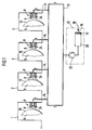
- Each rotating body 6 is assigned a blowing device 8, which blows cold air 9 onto the outer surface 10 of the rotating body 6.
- the cold air is generated by a cold air generator 12 and supplied to the blowing devices 8 via cold air supply lines 13 and 14.
- the cold air supply lines consist of a distributor line 13 and branch lines 14 branching therefrom.
- the cold air generator 12 contains an air inlet 16 in succession in the air flow direction with a filter 17 for sucking in and filtering fresh air 18, a unit 20 consisting of a cooler as a heat exchanger and a refrigeration system for supplying the cooler or heat exchanger with coolant, and a blower 22 for conveying the cold air via the cold air supply lines 13 and 14 to the blower device 8.
- the cooling effect of the cold air 9 on the outer surface 10 of the rotary body 6 can be changed by changing the temperature of the Cold air and / or can be controlled or regulated by changing the conveying speed of the cold air as a function of a setpoint.
- the setpoint value can be a temperature, for example, of the outer surface 10 of the rotating body 6 or of the cold air or of the refrigerant, which is used to cool the cold air.
- the target value can be a variable value, which is stored, for example, in the form of a control curve in a computer control system.
- the conveying speed of the cold air can be generated and changed by the blower 22 of the cold air generator 12 and / or a blower 24 which is located in the blowing device 8.
- FIG. 3 A further developed embodiment of the blowing device 8 of FIG. 1 is shown in FIG. 3 and there designated 8/1.
- the blowing device 8/1 or 8 has the shape of a box, which extends essentially over the entire length of the rotary body 6, is open to the rotary body 6 and has a narrow spacing gap at its edges 26 28 forms with the lateral surface 10 of the rotary body 6.
- the blowing device 8 can, according to FIG. 4, contain several blowers 11 distributed over the length of the rotating body 6. Each blower 11 is distributed over the length of the blowing device 8 and thus also over the length of the rotary body 6 in different cooling zones 31, 32 and 33. In each cooling zone, the cooling effect of the cold air is changed by changing the flow rate of this cold air or by changing the temperature of the Cold air individually adjustable.
- the flow rate can be adjusted individually by adjusting the speed of the blowers 11 or by adjusting adjustable flow restrictors 34, 35, 36.
- the flow restrictors 34, 35 and 36 are located in cooling zone feed lines 37, 38 and 39, which lead from the branch line 14 to the cooling zones 31, 32 and 33.
- a pressure regulator 40 can be located in the associated branch line 14.
- the cooling effect can be regulated or controlled individually by changing the temperature of the cold air for the individual zones.
- the blown air device 8/1 preferably consists of a box 42, in which a blown air duct 44 is formed radially to the lateral surface 10 of the rotary body 6, in the cold air inlet 46 of which the cold air feed lines 14 according to FIG. 1 or their cooling zone feed lines 37, 38 and 39 open radially to the rotating body 6 according to FIG. 4.
- the blown air duct 44 has, downstream of its cold air inlet 46, an inlet section 48 which is narrowed in the shape of a nozzle, then an enlarged channel section 49 and subsequently an outlet section 50 which is narrowed in the form of a nozzle.
- the nozzle-shaped constricted outlet section 50 accelerates the cold air flow so that it strikes the lateral surface 10 of the rotary body 6 at high speed.
- the inlet section 48 which is narrowed in the form of a nozzle, likewise produces an acceleration of the cold air flow. This accelerated cold air flow creates a vacuum in the expanded duct section 49 according to the Venturi principle.
- the blower 11 is expanded Channel section 49 housed and causes a further acceleration of the cold air flow.
- a first return duct 54/1 and 54/2 is formed separately by an intermediate wall 52 and 53, which together with the blown air duct 44 forms a first air recirculation circuit.
- the first return channels 54/1 and 54/2 each have an upstream inlet 56 opposite the lateral surface 10 of the rotary body 6, and a downstream outlet 58 into the expanded channel section 49 immediately downstream of the nozzle-shaped inlet section 48, but upstream of the blower 11 of the blown air channel 44.
- the cold air 60 of the blown air duct 44 is deflected by the outer surface 10 of the rotating body 6.
- the cold air escapes in the form of leakage currents 62 through the gaps 28 between the lateral surface 10 and the downstream edges 64 of the walls 52 and 53 of the blown air duct 44 Venturi principle and generated by the blower 11, sucked through the first return channels 54/1 and 54/2 into this expanded channel section 49 and admixed with the cold air inflow 66.
- blowing device 8/2 shown in FIG. 5 is of the same design as the embodiment shown in FIG. 3, but has no blower 11. As a result, the entire conveying capacity for conveying the cold air from the blower 22 shown in FIG Cold air generator 12 are generated.
- the first return channels 54/1 and 54/2 are delimited by outer channel walls 68 and 69, each of which is spaced apart run parallel to the inner channel walls 52 and 53. They have edges 70 which are spaced apart from the lateral surface 10 and form a downstream continuation 28/2 of the gap 28.
- the part 72 of the cold air leakage stream 62 which is not sucked off through the first return duct 54/1 and 54/2, escapes through the gap sections 28/2 and is largely sucked off into a second return duct 74/1 and 74/2.
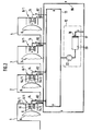
- These second return channels 74/1 and 74/2 are formed on the one hand by the channel walls 68 and 69 of the first return channel 54/1 and 54/2 and also by an upper and lower box wall 76 and have an inlet 78 and are connected in terms of flow at their downstream outlet 80 via a suction line 82 to the air inlet 16 of the cold air generator 12, as is shown in FIG. 2.
- the vacuum of the second return channels 74/1 and 74/2 required to extract the leakage air flow 72 is generated by the blower 22 of the cold air generator 12.
- the two second return channels 74/1 and 74/2 are connected to one another in terms of flow by a channel 84. In a modified embodiment, however, a separate suction line 82 could be connected to every second return duct. If several printing units according to FIG. 2 are connected to a common cold air generator 12, the suction lines 82 of each printing unit can be connected individually or according to FIG. 2 via a collecting suction line 86 to the air inlet 16 of the cold air generator 12.
- the suction effect of the fan 22 can be set so strongly that no cold air can escape from the box 42, but the entire remaining cold air leakage stream 72 is sucked off via the second return channels 74/1 and 74/2.
- FIG. 2 identically shows the blowing device 8/1 of FIG. 3 in the individual printing units 1, 2, 3 and 4.
- the outer second air recirculation circuit and the blowing device 8 shown in FIG. 1 are missing therefore has no second return channels 74/1 and 74/2, but only the first return channels 54/1 and 54/2.
- two blowing devices 8 are provided which are each directed against another rotating body 6/2 and 6/3 and are connected to one another by a wall 90.
- the two rotating bodies are, for example, printing cylinders of a printing unit. They are both on a common blanket roller 6/4. These three rotating bodies 6/2, 6/3 and 6/4 could also be inking unit rollers of a printing unit. Together with the two blowing devices 8 and their common wall 90, they delimit an intermediate space 92.
- This intermediate space 92 is connected in terms of flow via at least one outlet opening 93 and a suction line 94 connected thereto to the air inlet 16 of an external cold air generator 12. Functionally, the intermediate space 92 corresponds to the second return duct 74/1 or 74/2 from FIG.
- coolant flows through the heat exchanger or cooler 20 of the external cold air generator 12, which coolant flows from a refrigeration system 98 through coolant lines 99 to the heat exchanger and then back to the refrigeration system 98.
- the coolant can be water or refrigerant, which is cooled in the refrigeration system by compression and subsequent expansion. A heat exchange takes place between the coolant and the air in the heat exchanger 20.
- the blowing device 8, 8/1 or 8/2 can contain baffles or throttle valves for flow regulation.
Landscapes
- Engineering & Computer Science (AREA)
- Mechanical Engineering (AREA)
- Inking, Control Or Cleaning Of Printing Machines (AREA)
- Supply, Installation And Extraction Of Printed Sheets Or Plates (AREA)
- Electronic Switches (AREA)
- Heating, Cooling, Or Curing Plastics Or The Like In General (AREA)
Applications Claiming Priority (2)
| Application Number | Priority Date | Filing Date | Title |
|---|---|---|---|
| DE4307732A DE4307732A1 (de) | 1993-03-11 | 1993-03-11 | Temperierungsvorrichtung für Rotationskörper in Druckwerken |
| DE4307732 | 1993-03-11 |
Publications (3)
| Publication Number | Publication Date |
|---|---|
| EP0627308A2 true EP0627308A2 (fr) | 1994-12-07 |
| EP0627308A3 EP0627308A3 (fr) | 1995-01-18 |
| EP0627308B1 EP0627308B1 (fr) | 1997-04-09 |
Family
ID=6482533
Family Applications (1)
| Application Number | Title | Priority Date | Filing Date |
|---|---|---|---|
| EP94101700A Expired - Lifetime EP0627308B1 (fr) | 1993-03-11 | 1994-02-04 | Dispositif pour équilibrer la température des éléments rotatifs dans des groupes imprimants |
Country Status (5)
| Country | Link |
|---|---|
| US (1) | US5588360A (fr) |
| EP (1) | EP0627308B1 (fr) |
| JP (1) | JP2795802B2 (fr) |
| AT (1) | ATE151345T1 (fr) |
| DE (2) | DE4307732A1 (fr) |
Cited By (1)
| Publication number | Priority date | Publication date | Assignee | Title |
|---|---|---|---|---|
| US5881643A (en) * | 1995-11-08 | 1999-03-16 | Heidelberger Druckmaschinen Ag | Device for cooling the surface of a blanket of a printing unit cylinder |
Families Citing this family (17)
| Publication number | Priority date | Publication date | Assignee | Title |
|---|---|---|---|---|
| DE4335097C2 (de) * | 1993-10-14 | 1999-02-25 | Baldwin Grafotec Gmbh | Vorrichtung zum Temperieren von Druckmaschinenzylindern und -walzen |
| DE4440380A1 (de) * | 1994-11-11 | 1996-05-15 | Baldwin Gegenheimer Gmbh | Geräteschrank zur Bereitstellung von Prozeßwasser |
| US5791247A (en) * | 1995-12-18 | 1998-08-11 | Kolb; Daniel L. | Air system for controlling the discharge of printed material from a printing press and ink demulsifier |
| DE19926749B4 (de) * | 1999-06-11 | 2008-11-20 | Heidelberger Druckmaschinen Ag | Farbwerk für eine Druckmaschine |
| DE19942118A1 (de) * | 1999-09-03 | 2001-03-08 | Technotrans Ag | Verfahren zum Kühlen und Konditionieren von Luft für die Druckmaschinentemperierung sowie diesbezügliche Kühl- und Konditionierungsanordnung |
| US6851359B2 (en) * | 2001-06-22 | 2005-02-08 | Sparflex | Offset printing method and device |
| DE10152593A1 (de) * | 2001-10-24 | 2003-05-08 | Koenig & Bauer Ag | Einrichtung zur Bedruckstoff- und Druckwerkskühlung mittels gekühlter Blasluft an Bogenrotationsdruckmaschinen |
| DE20311534U1 (de) * | 2003-07-26 | 2003-10-09 | Roland Man Druckmasch | Einrichtung zur Farbwerksabsaugung |
| DE10334657A1 (de) * | 2003-07-30 | 2005-02-17 | Koenig & Bauer Ag | Verfahren und Einrichtung zur Bedruckstoff- und Druckmaschinenkühlung |
| JP2006297734A (ja) * | 2005-04-20 | 2006-11-02 | Komori Corp | 印刷機のエア吹き装置 |
| JP5093086B2 (ja) * | 2008-12-16 | 2012-12-05 | パナソニック株式会社 | スクリーン印刷機及びスクリーン印刷機の室内温度調節方法 |
| JP6985761B2 (ja) * | 2016-07-26 | 2021-12-22 | 株式会社富田技研 | 版胴冷却装置 |
| JP6780841B2 (ja) * | 2016-07-26 | 2020-11-04 | 株式会社富田技研 | 版胴冷却装置 |
| JP7319714B2 (ja) * | 2016-07-26 | 2023-08-02 | 株式会社富田技研 | 版胴冷却装置 |
| JP6998616B2 (ja) * | 2020-04-07 | 2022-01-18 | 三郷コンピュータホールディングス株式会社 | 印刷装置 |
| JP7793179B2 (ja) * | 2021-12-15 | 2026-01-05 | アインズ株式会社 | オフセット印刷システム及び温調装置 |
| CN117921194B (zh) * | 2024-01-22 | 2024-06-28 | 温州运城制版有限公司 | 一种具有散热机构的电雕版辊 |
Family Cites Families (9)
| Publication number | Priority date | Publication date | Assignee | Title |
|---|---|---|---|---|
| US2268987A (en) * | 1939-01-06 | 1942-01-06 | Interchem Corp | Method and apparatus for drying printing ink |
| US3628454A (en) * | 1969-07-16 | 1971-12-21 | United States Banknote Corp | Offset mister air die |
| JPS5531915A (en) * | 1978-08-29 | 1980-03-06 | Nippon Kogaku Kk <Nikon> | Portable refraction meter |
| JPS56127457A (en) * | 1980-03-13 | 1981-10-06 | Nippon Baldwin Kk | Cooler for ink roller |
| US5074213A (en) * | 1987-08-04 | 1991-12-24 | Seiichi Kurosawa | Thermoregulator of a block cylinder used for an offset press |
| JPH01114442A (ja) * | 1987-10-28 | 1989-05-08 | Tokyo Kikai Seisakusho Ltd | インキ供給装置 |
| DE4000912C1 (fr) * | 1990-01-15 | 1991-05-29 | Jagusch & Co, 8649 Wallenfels, De | |
| DE9101888U1 (de) * | 1990-07-04 | 1991-05-08 | Technotrans Böhnensieker GmbH, 4414 Sassenberg | Vorrichtung zur Bereitstellung von Prozesswasser für Druckmaschinen |
| DE9017795U1 (de) * | 1990-10-08 | 1992-03-12 | MAN Roland Druckmaschinen AG, 6050 Offenbach | Thermoregler für eine um einen Druckformzylinder gelegte Druckform für wasserlosen Offset-Druck |
-
1993
- 1993-03-11 DE DE4307732A patent/DE4307732A1/de not_active Withdrawn
-
1994
- 1994-02-04 AT AT94101700T patent/ATE151345T1/de not_active IP Right Cessation
- 1994-02-04 DE DE59402340T patent/DE59402340D1/de not_active Expired - Fee Related
- 1994-02-04 EP EP94101700A patent/EP0627308B1/fr not_active Expired - Lifetime
- 1994-02-28 JP JP6029913A patent/JP2795802B2/ja not_active Expired - Fee Related
- 1994-03-07 US US08/206,794 patent/US5588360A/en not_active Expired - Fee Related
Cited By (1)
| Publication number | Priority date | Publication date | Assignee | Title |
|---|---|---|---|---|
| US5881643A (en) * | 1995-11-08 | 1999-03-16 | Heidelberger Druckmaschinen Ag | Device for cooling the surface of a blanket of a printing unit cylinder |
Also Published As
| Publication number | Publication date |
|---|---|
| EP0627308A3 (fr) | 1995-01-18 |
| EP0627308B1 (fr) | 1997-04-09 |
| ATE151345T1 (de) | 1997-04-15 |
| DE4307732A1 (de) | 1994-09-15 |
| DE59402340D1 (de) | 1997-05-15 |
| JPH06316053A (ja) | 1994-11-15 |
| JP2795802B2 (ja) | 1998-09-10 |
| US5588360A (en) | 1996-12-31 |
Similar Documents
| Publication | Publication Date | Title |
|---|---|---|
| EP0627308B1 (fr) | Dispositif pour équilibrer la température des éléments rotatifs dans des groupes imprimants | |
| EP0638418B1 (fr) | Système de refroidissement pour cylindres de machines d'impression | |
| EP0553447B1 (fr) | Système de refroidissement de plaques d'impression pour une machine à imprimer | |
| EP0019780B1 (fr) | Dispositif de refroidissement pour modules de circuit imprimé | |
| EP1046874B1 (fr) | Sécheur avec unité de refroidissement intégré | |
| DE69003996T3 (de) | Vorrichtung zum Abkühlen einer aus einem Trockner kommenden Materialbahn. | |
| DE4016921A1 (de) | Vorrichtung zum trocknen einer materialbahn | |
| EP3650199B1 (fr) | Installation d'étirement de feuille | |
| EP0778131B1 (fr) | Système de guidage de feuilles pour une machine d'impression | |
| DE2753648A1 (de) | Klimaanlage | |
| EP1417442A1 (fr) | Dispositif et procede pour le recyclage de refrigerants ou de milieux de recyclage ou pour la production de froid | |
| DE69715963T2 (de) | Vorrichtung und Verfahren zum Trocknen einer feuchten Bahn und zum Modifizieren seines Feuchtigkeitsprofils | |
| DE2154771A1 (de) | Material-Kühleinrichtung mit Rückführung des Kühlgases | |
| DE9314967U1 (de) | Temperierungsvorrichtung für Rotationskörper in Druckwerken | |
| DE4426083A1 (de) | Druckmaschinen-Temperierungsvorrichtung | |
| DE19505971C5 (de) | Vorrichtung zum Trocknen von bedruckten oder beschichteten Bahnen | |
| DE2801258A1 (de) | Raum-klimaanlage | |
| DE2203621C3 (de) | Vorrichtung zum Trocknen von Materialbahnen | |
| EP1371924B1 (fr) | Appareil de séchage | |
| DE9218193U1 (de) | Druckmaschinen-Temperierungssystem | |
| DE3925905A1 (de) | Verfahren und vorrichtung zur aeroben, fermentativen hydrolyse, insbesondere zur kompostierung von organischen stoffen | |
| DE69019285T2 (de) | Klimagerät. | |
| DE9314968U1 (de) | Temperierungssystem für Druckmaschinenzylinder | |
| EP1331291A2 (fr) | Installation de texturation et buse de texturation correspondant | |
| DE1460574A1 (de) | Abdichtung am Ein- und Auslauf von Druckkammern bei Textilbehandlungsanlagen |
Legal Events
| Date | Code | Title | Description |
|---|---|---|---|
| PUAI | Public reference made under article 153(3) epc to a published international application that has entered the european phase |
Free format text: ORIGINAL CODE: 0009012 |
|
| PUAL | Search report despatched |
Free format text: ORIGINAL CODE: 0009013 |
|
| 17P | Request for examination filed |
Effective date: 19940204 |
|
| AK | Designated contracting states |
Kind code of ref document: A2 Designated state(s): AT BE CH DE ES FR GB IT LI NL SE |
|
| AK | Designated contracting states |
Kind code of ref document: A3 Designated state(s): AT BE CH DE ES FR GB IT LI NL SE |
|
| 17Q | First examination report despatched |
Effective date: 19960112 |
|
| GRAG | Despatch of communication of intention to grant |
Free format text: ORIGINAL CODE: EPIDOS AGRA |
|
| GRAH | Despatch of communication of intention to grant a patent |
Free format text: ORIGINAL CODE: EPIDOS IGRA |
|
| GRAH | Despatch of communication of intention to grant a patent |
Free format text: ORIGINAL CODE: EPIDOS IGRA |
|
| GRAA | (expected) grant |
Free format text: ORIGINAL CODE: 0009210 |
|
| AK | Designated contracting states |
Kind code of ref document: B1 Designated state(s): AT BE CH DE ES FR GB IT LI NL SE |
|
| PG25 | Lapsed in a contracting state [announced via postgrant information from national office to epo] |
Ref country code: NL Effective date: 19970409 Ref country code: ES Free format text: THE PATENT HAS BEEN ANNULLED BY A DECISION OF A NATIONAL AUTHORITY Effective date: 19970409 |
|
| REF | Corresponds to: |
Ref document number: 151345 Country of ref document: AT Date of ref document: 19970415 Kind code of ref document: T |
|
| REG | Reference to a national code |
Ref country code: CH Ref legal event code: NV Representative=s name: BOVARD AG PATENTANWAELTE Ref country code: CH Ref legal event code: EP |
|
| GBT | Gb: translation of ep patent filed (gb section 77(6)(a)/1977) |
Effective date: 19970410 |
|
| REF | Corresponds to: |
Ref document number: 59402340 Country of ref document: DE Date of ref document: 19970515 |
|
| ET | Fr: translation filed | ||
| NLV1 | Nl: lapsed or annulled due to failure to fulfill the requirements of art. 29p and 29m of the patents act | ||
| PG25 | Lapsed in a contracting state [announced via postgrant information from national office to epo] |
Ref country code: AT Free format text: LAPSE BECAUSE OF NON-PAYMENT OF DUE FEES Effective date: 19980204 |
|
| PLBE | No opposition filed within time limit |
Free format text: ORIGINAL CODE: 0009261 |
|
| STAA | Information on the status of an ep patent application or granted ep patent |
Free format text: STATUS: NO OPPOSITION FILED WITHIN TIME LIMIT |
|
| PG25 | Lapsed in a contracting state [announced via postgrant information from national office to epo] |
Ref country code: BE Free format text: LAPSE BECAUSE OF NON-PAYMENT OF DUE FEES Effective date: 19980228 |
|
| 26N | No opposition filed | ||
| BERE | Be: lapsed |
Owner name: BALDWIN-GEGENHEIMER G.M.B.H. Effective date: 19980228 |
|
| REG | Reference to a national code |
Ref country code: GB Ref legal event code: IF02 |
|
| PGFP | Annual fee paid to national office [announced via postgrant information from national office to epo] |
Ref country code: GB Payment date: 20030114 Year of fee payment: 10 |
|
| PGFP | Annual fee paid to national office [announced via postgrant information from national office to epo] |
Ref country code: FR Payment date: 20030218 Year of fee payment: 10 |
|
| PGFP | Annual fee paid to national office [announced via postgrant information from national office to epo] |
Ref country code: CH Payment date: 20030221 Year of fee payment: 10 Ref country code: SE Payment date: 20030221 Year of fee payment: 10 |
|
| PG25 | Lapsed in a contracting state [announced via postgrant information from national office to epo] |
Ref country code: GB Free format text: LAPSE BECAUSE OF NON-PAYMENT OF DUE FEES Effective date: 20040204 |
|
| PG25 | Lapsed in a contracting state [announced via postgrant information from national office to epo] |
Ref country code: SE Free format text: LAPSE BECAUSE OF NON-PAYMENT OF DUE FEES Effective date: 20040205 |
|
| PG25 | Lapsed in a contracting state [announced via postgrant information from national office to epo] |
Ref country code: LI Free format text: LAPSE BECAUSE OF NON-PAYMENT OF DUE FEES Effective date: 20040229 Ref country code: CH Free format text: LAPSE BECAUSE OF NON-PAYMENT OF DUE FEES Effective date: 20040229 |
|
| GBPC | Gb: european patent ceased through non-payment of renewal fee |
Effective date: 20040204 |
|
| EUG | Se: european patent has lapsed | ||
| REG | Reference to a national code |
Ref country code: CH Ref legal event code: PL |
|
| PG25 | Lapsed in a contracting state [announced via postgrant information from national office to epo] |
Ref country code: FR Free format text: LAPSE BECAUSE OF NON-PAYMENT OF DUE FEES Effective date: 20041029 |
|
| REG | Reference to a national code |
Ref country code: FR Ref legal event code: ST |
|
| PG25 | Lapsed in a contracting state [announced via postgrant information from national office to epo] |
Ref country code: IT Free format text: LAPSE BECAUSE OF NON-PAYMENT OF DUE FEES;WARNING: LAPSES OF ITALIAN PATENTS WITH EFFECTIVE DATE BEFORE 2007 MAY HAVE OCCURRED AT ANY TIME BEFORE 2007. THE CORRECT EFFECTIVE DATE MAY BE DIFFERENT FROM THE ONE RECORDED. Effective date: 20050204 |
|
| PGFP | Annual fee paid to national office [announced via postgrant information from national office to epo] |
Ref country code: DE Payment date: 20070213 Year of fee payment: 14 |
|
| PG25 | Lapsed in a contracting state [announced via postgrant information from national office to epo] |
Ref country code: DE Free format text: LAPSE BECAUSE OF NON-PAYMENT OF DUE FEES Effective date: 20080902 |