EP0627533A1 - Markise mit einem Tragprofil - Google Patents
Markise mit einem Tragprofil Download PDFInfo
- Publication number
- EP0627533A1 EP0627533A1 EP94107912A EP94107912A EP0627533A1 EP 0627533 A1 EP0627533 A1 EP 0627533A1 EP 94107912 A EP94107912 A EP 94107912A EP 94107912 A EP94107912 A EP 94107912A EP 0627533 A1 EP0627533 A1 EP 0627533A1
- Authority
- EP
- European Patent Office
- Prior art keywords
- drive
- awning
- hollow profile
- awning according
- gear
- Prior art date
- Legal status (The legal status is an assumption and is not a legal conclusion. Google has not performed a legal analysis and makes no representation as to the accuracy of the status listed.)
- Granted
Links
- 239000004744 fabric Substances 0.000 claims description 27
- 230000005540 biological transmission Effects 0.000 claims description 3
- 230000000717 retained effect Effects 0.000 abstract 1
- 230000002093 peripheral effect Effects 0.000 description 1
Images


Classifications
-
- E—FIXED CONSTRUCTIONS
- E04—BUILDING
- E04F—FINISHING WORK ON BUILDINGS, e.g. STAIRS, FLOORS
- E04F10/00—Sunshades, e.g. Florentine blinds or jalousies; Outside screens; Awnings or baldachins
- E04F10/02—Sunshades, e.g. Florentine blinds or jalousies; Outside screens; Awnings or baldachins of flexible canopy materials, e.g. canvas ; Baldachins
- E04F10/06—Sunshades, e.g. Florentine blinds or jalousies; Outside screens; Awnings or baldachins of flexible canopy materials, e.g. canvas ; Baldachins comprising a roller-blind with means for holding the end away from a building
- E04F10/0666—Accessories
- E04F10/0674—Accessories acting as separate supporting bar
-
- E—FIXED CONSTRUCTIONS
- E04—BUILDING
- E04F—FINISHING WORK ON BUILDINGS, e.g. STAIRS, FLOORS
- E04F10/00—Sunshades, e.g. Florentine blinds or jalousies; Outside screens; Awnings or baldachins
- E04F10/02—Sunshades, e.g. Florentine blinds or jalousies; Outside screens; Awnings or baldachins of flexible canopy materials, e.g. canvas ; Baldachins
- E04F10/06—Sunshades, e.g. Florentine blinds or jalousies; Outside screens; Awnings or baldachins of flexible canopy materials, e.g. canvas ; Baldachins comprising a roller-blind with means for holding the end away from a building
- E04F10/0611—Sunshades, e.g. Florentine blinds or jalousies; Outside screens; Awnings or baldachins of flexible canopy materials, e.g. canvas ; Baldachins comprising a roller-blind with means for holding the end away from a building with articulated arms supporting the movable end of the blind for deployment of the blind
- E04F10/0618—Sunshades, e.g. Florentine blinds or jalousies; Outside screens; Awnings or baldachins of flexible canopy materials, e.g. canvas ; Baldachins comprising a roller-blind with means for holding the end away from a building with articulated arms supporting the movable end of the blind for deployment of the blind whereby the pivot axis of the articulation is perpendicular to the roller
-
- E—FIXED CONSTRUCTIONS
- E04—BUILDING
- E04F—FINISHING WORK ON BUILDINGS, e.g. STAIRS, FLOORS
- E04F10/00—Sunshades, e.g. Florentine blinds or jalousies; Outside screens; Awnings or baldachins
- E04F10/02—Sunshades, e.g. Florentine blinds or jalousies; Outside screens; Awnings or baldachins of flexible canopy materials, e.g. canvas ; Baldachins
- E04F10/06—Sunshades, e.g. Florentine blinds or jalousies; Outside screens; Awnings or baldachins of flexible canopy materials, e.g. canvas ; Baldachins comprising a roller-blind with means for holding the end away from a building
- E04F10/0637—Sunshades, e.g. Florentine blinds or jalousies; Outside screens; Awnings or baldachins of flexible canopy materials, e.g. canvas ; Baldachins comprising a roller-blind with means for holding the end away from a building with mechanisms for adjusting the inclination of the blind
-
- E—FIXED CONSTRUCTIONS
- E04—BUILDING
- E04F—FINISHING WORK ON BUILDINGS, e.g. STAIRS, FLOORS
- E04F10/00—Sunshades, e.g. Florentine blinds or jalousies; Outside screens; Awnings or baldachins
- E04F10/02—Sunshades, e.g. Florentine blinds or jalousies; Outside screens; Awnings or baldachins of flexible canopy materials, e.g. canvas ; Baldachins
- E04F10/06—Sunshades, e.g. Florentine blinds or jalousies; Outside screens; Awnings or baldachins of flexible canopy materials, e.g. canvas ; Baldachins comprising a roller-blind with means for holding the end away from a building
- E04F10/0644—Sunshades, e.g. Florentine blinds or jalousies; Outside screens; Awnings or baldachins of flexible canopy materials, e.g. canvas ; Baldachins comprising a roller-blind with means for holding the end away from a building with mechanisms for unrolling or balancing the blind
-
- E—FIXED CONSTRUCTIONS
- E04—BUILDING
- E04F—FINISHING WORK ON BUILDINGS, e.g. STAIRS, FLOORS
- E04F10/00—Sunshades, e.g. Florentine blinds or jalousies; Outside screens; Awnings or baldachins
- E04F10/02—Sunshades, e.g. Florentine blinds or jalousies; Outside screens; Awnings or baldachins of flexible canopy materials, e.g. canvas ; Baldachins
- E04F10/06—Sunshades, e.g. Florentine blinds or jalousies; Outside screens; Awnings or baldachins of flexible canopy materials, e.g. canvas ; Baldachins comprising a roller-blind with means for holding the end away from a building
- E04F10/0685—Covers or housings for the rolled-up blind
Definitions
- the invention relates to an awning with a cloth roll rotatably held between two bearing cheeks for an awning cloth according to the preamble of claim 1.
- Such an awning with a support rod is known from DE-AS 1 955 577.
- a bearing cheek is arranged at each end of the support rod, between which the cloth roll is rotatably held.
- the drive for the cloth roll is arranged between a bearing cheek and an axial end of the cloth roll, for which purpose a separate housing is provided, which is relatively large.
- An inclination adjustment for support arms is also to be arranged on the support rod, again providing appropriate protection against the ingress of dirt and the like. If such an awning is to be electrically driven, the electric motor required for this must be provided in additional housings to be attached, so that different housings for the different types of drives must be kept available in series production.
- the invention has for its object to develop an awning of the generic type such that the necessary housing for different types of drives reduced are.
- the object is achieved in that the drive is built into the support rod designed as a hollow profile. This eliminates the need for additional housings because there is sufficient space along the length of the support rod to install different drive elements and also different drive types.
- the drive is housed in the support profile so that it is protected from the weather, so that simple drive elements which are otherwise only provided for dry rooms can be used.
- the drive is preferably arranged adjacent to a bearing cheek at the end of the support rod, an output shaft projecting through the bearing cheek and carrying an driven wheel which is in engagement with a drive member driving the cloth roller.
- This training ensures that the drive can remain completely in the hollow profile when dismantling the cloth roll; only the drive element driving the cloth roll is to be dismantled.
- the driven wheel and the drive member are therefore preferably arranged in a receptacle of the bearing cheek which can be closed by a cover.
- Each cantilever arm is advantageously connected to a tilt-adjustable articulated arm of a joint held in the hollow profile, wherein the articulated arm which can be pivoted about a horizontal axis can be tilted by means of a vertically lying screw spindle which can be rotated by a preferably vertical drive shaft via a gear held in the hollow profile.
- an inclination adjustment can be provided with the hollow profile otherwise unchanged; there is no need for separate housings to protect the drive of the inclination adjustment.
- the drive shaft can be actuated manually by a drive eyelet rotatably held in the bottom of the hollow profile or by an electric motor preferably arranged close to the bottom in the hollow profile without changes to the hollow profile being necessary.
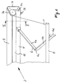
- the awning shown in Fig. 1 consists essentially of a support rod 5, which is designed as a hollow profile.
- the hollow profile of the support rod 5 is closed at its end 5a by a bearing cheek 3, the bearing cheeks having an approximately L-shaped shape and a cloth roll 2 for an awning cloth 1 being rotatably held between its legs 3a projecting from the supporting profile 5.
- the support rod 5 extends over the entire width of the cloth roll 1 and holds two spaced-apart cantilever arms 6, which together carry a drop rod 8.
- Each extension arm 6 consists of two arm sections 6a and 6b which are connected to one another via a joint 6c, the free end of the front arm section 6b carrying a head 6c which is rotatably connected to the extension rod 8.
- the rear arm section 6a is held on the support rod 5 by a joint 7 anchored in the hollow profile 5.
- the cloth roll 2 is protected by a cover 9 against rain and the like; the cover 9 is fixed to the support profile 5, which - as shown in FIG. 2 - is pulled up behind the cloth roll 2 and has a hanging edge 10 which is provided for hanging the hollow profile on the cantilever arm of a wall bracket, not shown.
- the cover 9 is preferably fixed on the hanging edge 10.
- a lower housing shell 15 is suspended in a fastening device 14 of the support profile 5 and engages around the cloth roll 2 over a circumferential angle of approximately 180 °.
- the cover 9 overlaps the lower shell, so that the cloth roll lies in a largely closed housing.
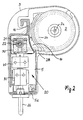
- a drive 20 is provided in the end section of the support profile 5, which is adjacent to a bearing cheek 3.
- a drive eye 26 is rotatably held in the base 5d of the hollow profile 5 and is connected in a rotationally fixed manner to a drive shaft 23 lying approximately perpendicular to the base 5d as the input shaft of the drive 20.
- the drive shaft 23 extends through a stop gear 30, which is shown in FIGS. 4 and 5 in detail. It consists of a gear housing 31, in which a locking ring 37, which is non-rotatably connected to the drive shaft 23, is arranged. With the locking ring 37, a gear 38 is connected, which meshes with a gear 34.
- gear wheel 34 meshes in parallel a further gear 36 which is rotatably connected to a second locking ring 35 which is rotatably mounted on the first locking ring 37.
- a further locking ring 39 meshes with a toothed ring of the gear wheel 34 which has a changed diameter. As FIG. 5 shows using the example of the locking ring 39, this has a partial circumference in its outer surface a recess 32; similar recesses have the locking rings 35 and 37. All three locking rings form a common peripheral surface on which a common, spring-loaded locking bolt 33 bears.
- the stop gear is designed such that, after a certain number of revolutions of the drive shaft 23, the locking rings are positioned in such a way that their recesses are congruent and the locking bolt 33 can engage, thereby preventing a further rotational movement of the drive shaft 23.
- the extension and / or retraction of the awning can be limited in a simple manner.
- the drive shaft 23 is also connected to a braking device 40, which is shown in detail in FIG. 6. It consists of a brake housing 41 which - as shown in FIG. 3 - is supported in a rotationally fixed manner with a radial extension in the hollow profile, in particular in the bearing cheek 3.
- the drive shaft 23 engages in a sleeve-shaped driver 43, which lies in a pot-shaped spring housing 42.
- the spring housing has an output shaft 44.
- a coil spring 45 is arranged on a sleeve 46.
- the sleeve 46 is held in a rotationally fixed manner via a disk 49 closing the brake housing;
- the brake housing is closed by a cover plate 48.
- the output shaft engages in an angular gear 50, which has an output shaft 21, whose axis of rotation is parallel to the axis of rotation 2a (Fig. 2) of the cloth shaft 2.
- the housing of the angular gear 50 is supported in a receptacle 50a of the bearing cheek 3; the output shaft 21 extends through the bearing cheek 3 and carries a driven gear 22, which is designed in particular as a chain wheel.
- the driven wheel lies in a receptacle 4 of the bearing cheek 3, the receptacle 4 being open to the outside.
- the receptacle 4 is closed by a cover, not shown.
- a drive link 23 is arranged on the driven wheel 22, which in the exemplary embodiment shown is a chain.
- the chain 23 meshes with a drive wheel 24 which is rotatably connected to the cloth roll 2. If a new awning cloth is to be installed, the cloth roll can be easily removed from the bearing cheeks 3 after removing the drive chain 23 without the drive itself having to be dismantled.
- an electric motor can be provided, as shown in FIGS. 7 and 8.
- the electric motor 51 drives the input shaft 52 of the angular gear 50 directly, so that a stop gear 30 and a braking device 40 can be omitted.
- the electric motor 51 is preferably provided with a flanged gear, the reduction is selected so that rotation from the input shaft 52 is only possible with an excessive torque, which is significantly higher than the braking torque required for the awning.
- the electric motor is controlled by appropriate limit switches, which is why the stop gear can be omitted.
- the electric motor 51 is preferably arranged near the floor and is adjacent to the rear wall of the hollow profile 5, preferably directly on the rear wall 5b.
- each extension arm 6 is connected to a tilt-adjustable articulated arm 7a, the articulated arm 7a being pivotable about a horizontal axis 7b.
- the articulated arm 7a is held between two articulated cheeks 7c, which are anchored in the supporting profile 5.
- the articulated cheeks 7c preferably form a box-shaped housing from which the articulated arm 7a protrudes.
- a screw spindle 70 on which a sliding block 71 is arranged, lies vertically to the bottom 5d of the hollow profile 5.
- the sliding block 71 is mounted in the articulated arm 7a so that the sliding block 71 can be displaced in the direction of the double arrow 72 by rotating the screw spindle 70, whereby the articulated arm 7a pivots in the direction of the double arrow 73 about the articulated axis 7b.
- a transmission gear 75 is arranged, which is arranged approximately above the joint 7 next to this in the hollow profile 5.
- the transmission gear 75 meshes with a drive gear 75a, which is arranged on the drive shaft 23 in a rotationally fixed manner.
- the drive gear 70a which is non-rotatably connected to the screw spindle 70, is rotated by means of corresponding gears, as a result of which the sliding block 71 is displaced in the direction of the double arrow 72, depending on the direction of rotation.
- the free end of the drive shaft 23 projects as an input shaft into an angular gear 50, the output shaft 77 of which runs parallel to the axis of rotation 2a of the roll of fabric in the longitudinal direction of the hollow profile 5.
- the output shaft 77 is a Connecting sleeve 78 connected to an angular gear, not shown, of the joint of the other cantilever arm in order to ensure a simultaneous inclination adjustment of both cantilever arms 6.
- the drive shaft 23 can be rotated manually by a drive eye 26 which is rotatably held in the base 5d, for which purpose a corresponding crank is to be hooked into the eye 26 projecting from the base 5d. It may be advantageous to arrange an electric motor 53 instead of the manual drive, as shown in FIG. 11.
- the electric motor 53 drives the drive shaft 23, wherein both tilt-adjustable joints 7 of the extension arms 6 can be actuated via the electric motor 53 and corresponding angular gear 50.
Landscapes
- Engineering & Computer Science (AREA)
- Architecture (AREA)
- Civil Engineering (AREA)
- Structural Engineering (AREA)
- Building Awnings And Sunshades (AREA)
- Tents Or Canopies (AREA)
Abstract
Description
- Die Erfindung betrifft eine Markise mit einer zwischen zwei Lagerwangen drehbar gehaltenen Tuchrolle für ein Markisentuch nach dem Oberbegriff des Anspruches 1.
- Eine derartige Markise mit einer Tragstange ist aus der DE-AS 1 955 577 bekannt. An den Enden der Tragstange ist je eine Lagerwange angeordnet, zwischen denen die Tuchrolle drehbar gehalten ist. Der Antrieb für die Tuchrolle ist dabei zwischen einer Lagerwange und einem axialen Ende der Tuchrolle angeordnet, wozu ein getrenntes Gehäuse vorgesehen ist, was relativ groß baut. Eine Neigungsverstellung für Tragarme ist zusätzlich an der Tragstange anzuordnen, wobei wieder ein entsprechender Schutz gegen Eindringen von Schmutz und dergleichen vorgesehen sein muß. Soll eine derartige Markise elektrisch angetrieben sein, muß der dafür notwendige Elektromotor in zusätzlich anzubringenden Gehäusen vorgesehen werden, so daß in der Serienproduktion unterschiedliche Gehäuse für die unterschiedlichen Antriebsarten zur Verfügung gehalten werden müssen.
- Der Erfindung liegt die Aufgabe zugrunde, eine Markise der gattungsgemäßen Art derart weiterzubilden, daß die notwendigen Gehäuse für unterschiedliche Antriebsarten vermindert sind.
- Die Aufgabe wird erfindungsgemäß dadurch gelöst, daß der Antrieb in die als Hohlprofil ausgebildete Tragstange eingebaut ist. Hierdurch entfallen zusätzliche Gehäuse, da über die Länge der Tragstange ausreichend Raum zur Verfügung steht, um unterschiedliche Antriebselemente und auch unterschiedliche Antriebsarten einzubauen. In dem Tragprofil ist der Antrieb wettergeschützt untergebracht, so daß einfache, ansonsten nur für Trockenräume vorgesehene Antriebselemente verwendet werden können.
- Bevorzugt ist der Antrieb benachbart zu einer Lagerwange am Ende der Tragstange angeordnet, wobei eine Abtriebswelle die Lagerwange durchragt und ein Abtriebsrad trägt, welches mit einem die Tuchrolle treibenden Antriebsglied in Eingriff steht. Diese Ausbildung stellt sicher, daß bei einer Demontage der Tuchrolle der Antrieb komplett im Hohlprofil verbleiben kann; lediglich das die Tuchrolle treibende Antriebsglied ist zu demontieren. Bevorzugt ist daher das Abtriebsrad und das Antriebsglied in einer durch einen Deckel verschließbaren Aufnahme der Lagerwange angeordnet. Vorteilhaft ist jeder Auslegerarm mit einem neigungsverstellbaren Gelenkarm eines im Hohlprofil gehaltenen Gelenkes verbunden, wobei der um eine horizontale Achse verschwenkbare Gelenkarm über eine vertikal liegende Schraubspindel neigungsverstellbar ist, die über ein im Hohlprofil gehaltenes Getriebe von einer vorzugsweise vertikalen Antriebswelle drehbar ist. Je nach Wunsch des Kunden kann so eine Neigungsverstellung bei ansonsten unverändertem Hohlprofil vorgesehen werden; separate Gehäuse zum Schutz des Antriebes der Neigungsverstellung entfallen.
- Die Antriebswelle kann manuell von einer im Boden des Hohlprofiles drehbar gehaltenen Antriebsöse betätigt sein oder von einem vorzugsweise bodennah im Hohlprofil angeordneten Elektromotor, ohne daß Änderungen am Hohlprofil notwendig sind.
- Weitere Merkmale der Erfindung ergeben sich aus den weiteren Ansprüchen, der Beschreibung und der Zeichnung, in der nachfolgend im einzelnen beschriebene Ausführungsbeispiele der Erfindung dargestellt sind. Es zeigen:
- Fig. 1
- eine perspektivische Teilansicht einer erfindungsgemäßen Markise,
- Fig. 2
- einen Schnitt längs der Linie II-II in Fig. 1,
- Fig. 3
- einen Längsschnitt durch einen Endabschnitt des Tragprofiles der erfindungsgemäßen Markise,
- Fig. 4
- einen Schnitt durch ein Anschlaggetriebe,
- Fig. 5
- eine Ansicht auf das Anschlaggetriebe von unten,
- Fig. 6
- einen Schnitt durch eine Bremsvorrichtung,
- Fig. 7
- einen Längsschnitt durch den Endabschnitt des Tragprofiles der erfindungsgemäßen Markise mit elektrischem Antrieb für die Tuchrolle,
- Fig. 8
- einen Schnitt durch das Tragprofil mit elektrischem Antrieb für die Tuchrolle,
- Fig. 9
- einen Längsschnitt durch das Tragprofil mit einem manuellen Antrieb für eine Neigungsverstellung der Auslegerarme,
- Fig. 10
- eine Seitenansicht auf eine Neigungsverstellung gemäß Fig. 9,
- Fig. 11
- einen Schnitt durch ein Tragprofil mit elektrischem Antrieb für eine Neigungsverstellung.
- Die in Fig. 1 dargestellte Markise besteht im wesentlichen aus einer Tragstange 5, welche als Hohlprofil ausgebildet ist. Das Hohlprofil der Tragstange 5 ist an seinem Ende 5a jeweils durch eine Lagerwange 3 verschlossen, wobei die Lagerwangen eine etwa L-förmige Gestalt aufweisen und zwischen ihren vom Tragprofil 5 wegragenden Schenkeln 3a eine Tuchrolle 2 für ein Markisentuch 1 drehbar gehalten ist. Die Tragstange 5 erstreckt sich über die gesamte Breite der Tuchrolle 1 und hält zwei mit Abstand voneinander liegende Auslegerarme 6, die gemeinsam eine Ausfallstange 8 tragen. Jeder Auslegerarm 6 besteht aus zwei über ein Gelenk 6c miteinander verbundenen Armabschnitten 6a und 6b, wobei das freie Ende des vorderen Armabschnittes 6b einen Kopf 6c trägt, welcher drehbar mit der Ausfallstange 8 verbunden ist. Der hintere Armabschnitt 6a ist mit einem im Hohlprofil 5 verankerten Gelenk 7 an der Tragstange 5 gehalten.
- Die Tuchrolle 2 ist durch eine Abdeckung 9 gegen Regen und dergleichen geschützt; die Abdeckung 9 ist am Tragprofil 5 festgelegt, welches - wie Fig. 2 zeigt - bis hinter die Tuchrolle 2 hochgezogen ist und einen Einhängerand 10 aufweist, welcher zum Einhängen des Hohlprofiles an dem Kragarm einer nicht näher dargestellten Wandhalterung vorgesehen ist. Die Abdeckung 9 ist vorzugsweise auf dem Einhängerand 10 festgelegt. Eine Gehäuseunterschale 15 ist in eine Befestigungsvorrichtung 14 des Tragprofiles 5 eingehängt und umgreift die Tuchrolle 2 über einen Umfangswinkel von etwa 180°. Die Abdeckung 9 übergreift dabei die Unterschale, so daß die Tuchrolle in einem weitgehend geschlossenen Gehäuse liegt.
- Wie die Fig. 2 und 3 zeigen, ist im Endabschnitt des Tragprofiles 5 ein Antrieb 20 vorgesehen, der benachbart zu einer Lagerwange 3 liegt. Im Ausführungsbeispiel der Fig. 2 und 3 ist im Boden 5d des Hohlprofiles 5 eine Antriebsöse 26 drehbar gehalten, welche drehfest mit einer etwa lotrecht zum Boden 5d liegenden Antriebswelle 23 als Eingangswelle des Antriebes 20 verbunden ist. Die Antriebswelle 23 durchragt ein Anschlaggetriebe 30, welches in den Fig. 4 und 5 im einzelnen dargestellt ist. Es besteht aus einem Getriebegehäuse 31, in dem ein drehfest mit der Antriebswelle 23 verbundener Sperring 37 angeordnet ist. Mit dem Sperring 37 ist ein Zahnrad 38 verbunden, welches mit einem Getrieberad 34 kämmt. Mit diesem Getrieberad 34 kämmt parallel ein weiteres Zahnrad 36, welches drehfest mit einem zweiten Sperring 35 verbunden ist, der auf dem ersten Sperring 37 drehbar gelagert ist. Ein weiterer Sperring 39 kämmt mit einem im Durchmesser veränderten Zahnkranz des Getrieberades 34. Wie Fig. 5 am Beispiel des Sperrings 39 zeigt, weist dieser über einen Teilumfang in seiner Mantelfläche eine Ausnehmung 32 auf; ähnliche Ausnehmungen weisen die Sperringe 35 und 37 auf. Alle drei Sperringe bilden eine gemeinsame Umfangsfläche, an der ein gemeinsamer, federbelasteter Sperriegel 33 anliegt. Das Anschlaggetriebe ist derart ausgelegt, daß nach einer bestimmten Anzahl von Umdrehungen der Antriebswelle 23 die Sperringe derart stehen, daß ihre Ausnehmungen deckungsgleich liegen und der Sperriegel 33 einfallen kann, wodurch eine weitere Drehbewegung der Antriebswelle 23 verhindert ist. Das Ausfahren und/oder Einfahren der Markise kann so auf einfache Weise begrenzt werden.
- Um eine teilausgefahrene Markise in ihrer Stellung zu sichern, ist die Antriebswelle 23 ferner mit einer Bremsvorrichtung 40 verbunden, die in Fig. 6 im einzelnen dargestellt ist. Sie besteht aus einem Bremsgehäuse 41, welches - wie Fig. 3 zeigt - mit einem radialen Fortsatz im Hohlprofil, insbesondere in der Lagerwange 3 drehfest abgestützt ist. Die Antriebswelle 23 greift in einen hülsenförmig ausgebildeten Mitnehmer 43 ein, der in einem topfförmig ausgebildeten Federgehäuse 42 liegt. Das Federgehäuse weist eine Ausgangswelle 44 auf. Auf einer Hülse 46 ist eine Schraubenfeder 45 angeordnet. Die Hülse 46 ist über eine das Bremsgehäuse verschließende Scheibe 49 drehfest gehalten; über eine Abschlußscheibe 48 ist das Bremsgehäuse verschlossen. Bei einem Drehmoment auf die Ausgangswelle wird das Federgehäuse an das Bremsgehäuse angelegt, wodurch das Drehmoment abgestütz ist; wird hingegen von der Antriebswelle 23 her der Mitnehmer 43 gedreht, wird das Bremsmoment aufgehoben und die Ausgangswelle 44 gedreht.
- Wie Fig. 3 zeigt, greift die Ausgangswelle in ein Winkelgetriebe 50 ein, welches eine Abtriebswelle 21 aufweist, deren Drehachse parallel zur Drehachse 2a (Fig. 2) der Tuchwelle 2 liegt. Das Gehäuse des Winkelgetriebes 50 ist in einer Aufnahme 50a der Lagerwange 3 abgestützt; die Abtriebswelle 21 durchragt die Lagerwange 3 und trägt ein insbesondere als Kettenrad ausgebildetes Abtriebsrad 22. Das Abtriebsrad liegt in einer Aufnahme 4 der Lagerwange 3, wobei die Aufnahme 4 nach außen offen ist. Die Aufnahme 4 wird durch einen nicht dargestellten Deckel verschlossen.
- Auf dem Abtriebsrad 22 ist ein Antriebsglied 23 angeordnet, welches im gezeigten Ausführungsbeispiel eine Kette ist. Die Kette 23 kämmt mit einem Antriebsrad 24, das drehfest mit der Tuchrolle 2 verbunden ist. Soll ein neues Markisentuch montiert werden, ist die Tuchrolle nach Abnahme der Antriebskette 23 leicht aus den Lagerwangen 3 auszubauen, ohne daß der Antrieb an sich zu demontieren ist.
- Anstelle eines in den Fig. 2 und 3 dargestellten manuellen Antriebes kann ein Elektromotor vorgesehen sein, wie die Fig. 7 und 8 zeigen. Der Elektromotor 51 treibt unmittelbar die Eingangswelle 52 des Winkelgetriebes 50 an, so daß ein Anschlaggetriebe 30 sowie eine Bremsvorrichtung 40 entfallen können. Dies deshalb, da der Elektromotor 51 vorzugsweise mit einem angeflanschten Getriebe versehen ist, dessen Untersetzung so gewählt ist, daß eine Drehung von seiten der Eingangswelle 52 her nur mit einem überhöhten Drehmoment möglich ist, welches deutlich höher als das notwendige Bremsmoment für die Markise ist. Der Elektromotor ist durch entsprechende Endschalter gesteuert, weshalb das Anschlaggetriebe entfallen kann. Bevorzugt ist der Elektromotor 51 bodennah angeordnet und liegt benachbart zur Rückwand des Hohlprofiles 5, bevorzugt unmittelbar an der Rückwand 5b.
- Im Ausführungsbeispiel der Fig. 9 und 10 ist ein Antrieb 20 für die Neigungsverstellung der Auslegearme 6 gezeigt. Jeder Auslegearm 6 ist mit einem neigungsverstellbaren Gelenkarm 7a verbunden, wobei der Gelenkarm 7a um eine horizontale Achse 7b verschwenkbar ist. Hierzu ist der Gelenkarm 7a zwischen zwei Gelenkwangen 7c gehalten, die im Tragprofil 5 verankert sind. Die Gelenkwangen 7c bilden bevorzugt ein kastenförmiges Gehäuse, aus dem der Gelenkarm 7a herausragt.
- Wie Fig. 10 zeigt, liegt vertikal zum Boden 5d des Hohlprofiles 5 eine Schraubspindel 70, auf der ein Kulissenstein 71 angeordnet ist. Der Kulissenstein 71 ist im Gelenkarm 7a gelagert, so daß durch Drehung der Schraubspindel 70 der Kulissenstein 71 in Richtung des Doppelpfeiles 72 verschiebbar ist, wodurch der Gelenkarm 7a um die Gelenkachse 7b in Richtung des Doppelpfeiles 73 verschwenkt.
- Zur Drehung der Schraubspindel 70 ist ein Übersetzungsgetriebe 75 angeordnet, welches etwa oberhalb des Gelenkes 7 neben diesem im Hohlprofil 5 angeordnet ist. Das Übersetzungsgetriebe 75 kämmt mit einem Antriebszahnrad 75a, welches auf der Antriebswelle 23 drehfest angeordnet ist. Über entsprechende Zahnräder wird das drehfest mit der Schraubspindel 70 verbundene Antriebszahnrad 70a gedreht, wodurch der Kulissenstein 71 in Richtung des Doppelpfeiles 72 - je nach Drehrichtung - verschoben wird.
- Das freie Ende der Antriebswelle 23 ragt als Eingangswelle in ein Winkelgetriebe 50, dessen Abtriebswelle 77 parallel zur Drehachse 2a der Tuchrolle in Längsrichtung des Hohlprofiles 5 verläuft. Die Abtriebswelle 77 ist über eine Verbindungsmuffe 78 mit einem nicht näher dargestellten Winkelgetriebe des Gelenkes des anderen Auslegerarmes verbunden, um eine gleichzeitige Neigungsverstellung beider Auslegerarme 6 zu gewährleisten.
- Im Ausführungsbeispiel der Fig. 9 und 10 ist die Antriebswelle 23 von einer im Boden 5d drehbar gehaltenen Antriebsöse 26 manuell drehbar, wozu eine entsprechende Kurbel in die vom Boden 5d abstehende Öse 26 einzuhängen ist. Es kann vorteilhaft sein, anstelle des manuellen Antriebes einen Elektromotor 53 anzuordnen, wie dies in Fig. 11 dargestellt ist. Der Elektromotor 53 treibt die Antriebswelle 23, wobei über den Elektromotor 53 und entsprechende Winkelgetriebe 50 beide neigungsverstellbaren Gelenke 7 der Auslegerarme 6 betätigbar sind.
Claims (10)
- Markise mit einer zwischen zwei Lagerwangen (3) drehbar gehaltenen Tuchrolle (2) für ein Markisentuch (1), wobei je eine Lagerwange (3) an einem Ende (5a) einer Tragstange (5) festliegt, die sich über die Länge der Tuchrolle (2) erstreckt, und mit an der Tragstange (5) befestigten Auslegerarmen (6) für eine Ausfallstange (8), an der das Markisentuch (1) festlegbar ist, sowie einen Antrieb (20) für die Tuchrolle (2),
dadurch gekennzeichnet, daß der Antrieb (20) in der als Hohlprofil ausgebildeten Tragstange (5) angeordnet ist. - Markise nach Anspruch 1,
dadurch gekennzeichnet, daß der Antrieb (20) benachbart zu einer Lagerwange (3) am Ende (5a) der Tragstange (5) angeordnet ist. - Markise nach Anspruch 1 oder 2,
dadurch gekennzeichnet, daß eine Abtriebswelle (21) des Antriebes (20) die Lagerwange (3) durchragt und ein Abtriebsrad (22) trägt, welches mit einem die Tuchrolle (2) treibenden Antriebsglied (28) in Eingriff steht, wobei vorzugsweise das Abtriebsrad (22) ein Kettenrad und das Antriebsglied (28) eine Kette ist, welche mit einem Antriebsrad (24) der Tuchrolle kämmt. - Markise nach einem der Ansprüche 1 bis 3,
dadurch gekennzeichnet, daß die Lagerwange (3) ein das Hohlprofil (5) endseitig verschließenden Deckel bildet. - Markise nach Anspruch 3 oder 4,
dadurch gekennzeichnet, daß das Abtriebsrad (22) und das Antriebsglied (28) in einer durch einen Deckel verschließbaren Aufnahme (4) der Lagerwange (3) liegen. - Markise nach einem der Ansprüche 3 bis 5,
dadurch gekennzeichnet, daß die Abtriebswelle (21) Teil eines Winkelgetriebes (50) ist, dessen Eingangswelle (23) etwa lotrecht zum Boden (5d) des Hohlprofiles (5) liegt, wobei das Winkelgetriebe (50) vorzugsweise in der Lagerwange (3) gehalten ist. - Markise nach Anspruch 7,
dadurch gekennzeichnet, daß die Eingangswelle (23) mit einem vorzugsweise im Hohlprofil (5) gehaltenen Anschlaggetriebe (30) und/oder mit einer vorzugsweise im Hohlprofil (5) gehaltenen Bremsvorrichtung (40) in Verbindung steht. - Markise nach einem der Ansprüche 1 bis 7,
dadurch gekennzeichnet, daß jeder Auslegerarm (6) mit einem neigungsverstellbaren Gelenkarm (7a) eines im Hohlprofil (5) gehaltenen Gelenkes (7) verbunden ist. - Markise nach Anspruch 8,
dadurch gekennzeichnet, daß der um eine horizontale Achse (7b) verschwenkbare Gelenkarm (7a) über eine vertikal liegende Schraubspindel (70) neigungsverstellbar ist, die über ein im Hohlprofil (5) gehaltenes Getriebe (75) von einer vertikalen Antriebswelle (23) drehbar ist, wobei vorzugsweise die Schraubspindel (70) und das Getriebe (75) nebeneinander liegen. - Markise nach Anspruch 8 oder 9,
dadurch gekennzeichnet, daß die eine Ausfallstange (8) haltenden Auslegerarme (6) über eine gemeinsame Antriebswelle (23) verstellbar sind, wobei die Antriebswelle (23) manuell von einer im Boden (5d) des Hohlprofiles (5) gelagerten Antriebsöse (26) oder von einem vorzugsweise bodennah im Hohlprofil (5) angeordneten Elektromotor (51) drehbar ist.
Applications Claiming Priority (2)
| Application Number | Priority Date | Filing Date | Title |
|---|---|---|---|
| DE4318437A DE4318437A1 (de) | 1993-06-03 | 1993-06-03 | Markise mit einem Tragprofil |
| DE4318437 | 1993-06-03 |
Publications (2)
| Publication Number | Publication Date |
|---|---|
| EP0627533A1 true EP0627533A1 (de) | 1994-12-07 |
| EP0627533B1 EP0627533B1 (de) | 1998-03-04 |
Family
ID=6489537
Family Applications (1)
| Application Number | Title | Priority Date | Filing Date |
|---|---|---|---|
| EP94107912A Expired - Lifetime EP0627533B1 (de) | 1993-06-03 | 1994-05-21 | Markise mit einem Tragprofil |
Country Status (3)
| Country | Link |
|---|---|
| EP (1) | EP0627533B1 (de) |
| AT (1) | ATE163716T1 (de) |
| DE (2) | DE4318437A1 (de) |
Cited By (1)
| Publication number | Priority date | Publication date | Assignee | Title |
|---|---|---|---|---|
| WO1999061721A3 (de) * | 1998-05-28 | 2000-02-24 | Mueller Hermann Frank | Awning with flexible solar modules |
Families Citing this family (1)
| Publication number | Priority date | Publication date | Assignee | Title |
|---|---|---|---|---|
| DE102020131347A1 (de) | 2020-11-26 | 2022-06-02 | Stobag Ag | Beschattungsvorrichtung |
Citations (4)
| Publication number | Priority date | Publication date | Assignee | Title |
|---|---|---|---|---|
| DE2752872A1 (de) * | 1977-11-26 | 1979-05-31 | Weiermann Dieter Weinor | Kippgelenk fuer markisen o.dgl. |
| EP0135731A2 (de) * | 1983-09-23 | 1985-04-03 | Clauss Markisen | Markise mit nachgiebiger Motorkupplung |
| FR2596100A1 (fr) * | 1986-03-21 | 1987-09-25 | Mitjavila Raymond | Dispositif de reglage de l'inclinaison de bras retractables pour stores a l'italienne et similaires |
| EP0509471A1 (de) * | 1991-04-19 | 1992-10-21 | TR.EM. S.r.l. | Verriegelungsvorrichtung für Markisen |
-
1993
- 1993-06-03 DE DE4318437A patent/DE4318437A1/de not_active Withdrawn
-
1994
- 1994-05-21 DE DE59405338T patent/DE59405338D1/de not_active Expired - Fee Related
- 1994-05-21 AT AT94107912T patent/ATE163716T1/de not_active IP Right Cessation
- 1994-05-21 EP EP94107912A patent/EP0627533B1/de not_active Expired - Lifetime
Patent Citations (4)
| Publication number | Priority date | Publication date | Assignee | Title |
|---|---|---|---|---|
| DE2752872A1 (de) * | 1977-11-26 | 1979-05-31 | Weiermann Dieter Weinor | Kippgelenk fuer markisen o.dgl. |
| EP0135731A2 (de) * | 1983-09-23 | 1985-04-03 | Clauss Markisen | Markise mit nachgiebiger Motorkupplung |
| FR2596100A1 (fr) * | 1986-03-21 | 1987-09-25 | Mitjavila Raymond | Dispositif de reglage de l'inclinaison de bras retractables pour stores a l'italienne et similaires |
| EP0509471A1 (de) * | 1991-04-19 | 1992-10-21 | TR.EM. S.r.l. | Verriegelungsvorrichtung für Markisen |
Cited By (1)
| Publication number | Priority date | Publication date | Assignee | Title |
|---|---|---|---|---|
| WO1999061721A3 (de) * | 1998-05-28 | 2000-02-24 | Mueller Hermann Frank | Awning with flexible solar modules |
Also Published As
| Publication number | Publication date |
|---|---|
| DE4318437A1 (de) | 1994-12-08 |
| ATE163716T1 (de) | 1998-03-15 |
| EP0627533B1 (de) | 1998-03-04 |
| DE59405338D1 (de) | 1998-04-09 |
Similar Documents
| Publication | Publication Date | Title |
|---|---|---|
| DE69000367T2 (de) | Vorhang mit motorisierter aufwickelvorrichtung. | |
| DE2514941A1 (de) | Markise | |
| DE2034321C3 (de) | Lamellenvorhang | |
| DE68905328T2 (de) | Dachöffnungseinrichtung für ein Industriefahrzeug mit einer Wagenplane. | |
| DE3518371C2 (de) | ||
| DE102009053991B3 (de) | Türantrieb für eine Schwenktür eines Fahrzeugs zum Personentransport | |
| DE3839870C2 (de) | Seitenzug-Caliperbremse | |
| EP0627533B1 (de) | Markise mit einem Tragprofil | |
| DE2746793A1 (de) | Rueckblickspiegel mit distanzbetaetigung | |
| EP0631025B1 (de) | Markise mit einer Tragstange | |
| DE29619988U1 (de) | Patientenlifter mit mechanischer Notabsenkung | |
| DE4203149C1 (en) | Moving and tensioning mechanism for awnings and blinds - has brake discs at ends of fabric support roller, axially slidable in roller hub and rotating with it | |
| EP0872611A2 (de) | Markise, insbesondere Gelenkarmmarkise | |
| EP0187388A2 (de) | Höhenverstellbares Abstützgerät, insbesondere Sattelaufliegerstütze | |
| DE29821879U1 (de) | Sonnenblendenanordnung mit senkrecht verlaufenden Schienen | |
| EP0933491B1 (de) | Vorrichtung zum Beschatten eines Raumes | |
| EP0618340B1 (de) | Antriebsvorrichtung für eine Lamellenjalousie, insbesondere für Dachfenster | |
| DE513296C (de) | Um einen waagerechten Kragarm einer Strassenkehrvorrichtung drehbare und gegen die Achse der Kehrbuerste in einer senkrechten Ebene schwenkbare Rinnsteinkehrbuerste | |
| DE2010721C (de) | Raffbare Lamellenjalousie | |
| DE2527860C3 (de) | Teilkreismarkise | |
| DE2241662C3 (de) | Aufrollbare Markise | |
| DE3440446C2 (de) | ||
| DE2529401C3 (de) | Verstelleinrichtung für Gelenkarmmarkisen | |
| DE69505901T2 (de) | Vorrichtung zum Erleichtern das Montieren von Schleifbändern auf Schleifmaschinen, insbesondere für Holztafeln | |
| DE2621134A1 (de) | Knickarmmarkise |
Legal Events
| Date | Code | Title | Description |
|---|---|---|---|
| PUAI | Public reference made under article 153(3) epc to a published international application that has entered the european phase |
Free format text: ORIGINAL CODE: 0009012 |
|
| AK | Designated contracting states |
Kind code of ref document: A1 Designated state(s): AT BE CH DE DK ES FR GB GR IE IT LI LU MC NL PT SE |
|
| 17P | Request for examination filed |
Effective date: 19950602 |
|
| 17Q | First examination report despatched |
Effective date: 19960624 |
|
| GRAG | Despatch of communication of intention to grant |
Free format text: ORIGINAL CODE: EPIDOS AGRA |
|
| GRAG | Despatch of communication of intention to grant |
Free format text: ORIGINAL CODE: EPIDOS AGRA |
|
| GRAH | Despatch of communication of intention to grant a patent |
Free format text: ORIGINAL CODE: EPIDOS IGRA |
|
| GRAH | Despatch of communication of intention to grant a patent |
Free format text: ORIGINAL CODE: EPIDOS IGRA |
|
| GRAA | (expected) grant |
Free format text: ORIGINAL CODE: 0009210 |
|
| AK | Designated contracting states |
Kind code of ref document: B1 Designated state(s): AT BE CH DE DK ES FR GB GR IE IT LI LU MC NL PT SE |
|
| PG25 | Lapsed in a contracting state [announced via postgrant information from national office to epo] |
Ref country code: NL Free format text: LAPSE BECAUSE OF FAILURE TO SUBMIT A TRANSLATION OF THE DESCRIPTION OR TO PAY THE FEE WITHIN THE PRESCRIBED TIME-LIMIT Effective date: 19980304 Ref country code: IT Free format text: LAPSE BECAUSE OF FAILURE TO SUBMIT A TRANSLATION OF THE DESCRIPTION OR TO PAY THE FEE WITHIN THE PRE;WARNING: LAPSES OF ITALIAN PATENTS WITH EFFECTIVE DATE BEFORE 2007 MAY HAVE OCCURRED AT ANY TIME BEFORE 2007. THE CORRECT EFFECTIVE DATE MAY BE DIFFERENT FROM THE ONE RECORDED.SCRIBED TIME-LIMIT Effective date: 19980304 Ref country code: GR Free format text: LAPSE BECAUSE OF FAILURE TO SUBMIT A TRANSLATION OF THE DESCRIPTION OR TO PAY THE FEE WITHIN THE PRESCRIBED TIME-LIMIT Effective date: 19980304 Ref country code: GB Free format text: LAPSE BECAUSE OF FAILURE TO SUBMIT A TRANSLATION OF THE DESCRIPTION OR TO PAY THE FEE WITHIN THE PRESCRIBED TIME-LIMIT Effective date: 19980304 Ref country code: FR Free format text: LAPSE BECAUSE OF FAILURE TO SUBMIT A TRANSLATION OF THE DESCRIPTION OR TO PAY THE FEE WITHIN THE PRESCRIBED TIME-LIMIT Effective date: 19980304 Ref country code: ES Free format text: THE PATENT HAS BEEN ANNULLED BY A DECISION OF A NATIONAL AUTHORITY Effective date: 19980304 |
|
| REF | Corresponds to: |
Ref document number: 163716 Country of ref document: AT Date of ref document: 19980315 Kind code of ref document: T |
|
| REG | Reference to a national code |
Ref country code: CH Ref legal event code: EP |
|
| REF | Corresponds to: |
Ref document number: 59405338 Country of ref document: DE Date of ref document: 19980409 |
|
| PG25 | Lapsed in a contracting state [announced via postgrant information from national office to epo] |
Ref country code: LU Free format text: LAPSE BECAUSE OF NON-PAYMENT OF DUE FEES Effective date: 19980521 Ref country code: AT Free format text: LAPSE BECAUSE OF NON-PAYMENT OF DUE FEES Effective date: 19980521 |
|
| PG25 | Lapsed in a contracting state [announced via postgrant information from national office to epo] |
Ref country code: LI Free format text: LAPSE BECAUSE OF NON-PAYMENT OF DUE FEES Effective date: 19980531 Ref country code: CH Free format text: LAPSE BECAUSE OF NON-PAYMENT OF DUE FEES Effective date: 19980531 Ref country code: BE Free format text: LAPSE BECAUSE OF NON-PAYMENT OF DUE FEES Effective date: 19980531 |
|
| PG25 | Lapsed in a contracting state [announced via postgrant information from national office to epo] |
Ref country code: SE Free format text: LAPSE BECAUSE OF FAILURE TO SUBMIT A TRANSLATION OF THE DESCRIPTION OR TO PAY THE FEE WITHIN THE PRESCRIBED TIME-LIMIT Effective date: 19980604 Ref country code: PT Free format text: LAPSE BECAUSE OF FAILURE TO SUBMIT A TRANSLATION OF THE DESCRIPTION OR TO PAY THE FEE WITHIN THE PRESCRIBED TIME-LIMIT Effective date: 19980604 Ref country code: DK Free format text: LAPSE BECAUSE OF FAILURE TO SUBMIT A TRANSLATION OF THE DESCRIPTION OR TO PAY THE FEE WITHIN THE PRESCRIBED TIME-LIMIT Effective date: 19980604 |
|
| REG | Reference to a national code |
Ref country code: IE Ref legal event code: FG4D Free format text: 79142 |
|
| EN | Fr: translation not filed | ||
| NLV1 | Nl: lapsed or annulled due to failure to fulfill the requirements of art. 29p and 29m of the patents act | ||
| GBV | Gb: ep patent (uk) treated as always having been void in accordance with gb section 77(7)/1977 [no translation filed] |
Effective date: 19980304 |
|
| PG25 | Lapsed in a contracting state [announced via postgrant information from national office to epo] |
Ref country code: IE Free format text: LAPSE BECAUSE OF NON-PAYMENT OF DUE FEES Effective date: 19980924 |
|
| REG | Reference to a national code |
Ref country code: IE Ref legal event code: FD4D Ref document number: 79142 Country of ref document: IE |
|
| BERE | Be: lapsed |
Owner name: RAU METALL G.M.B.H. & CO. Effective date: 19980531 |
|
| PG25 | Lapsed in a contracting state [announced via postgrant information from national office to epo] |
Ref country code: MC Free format text: LAPSE BECAUSE OF NON-PAYMENT OF DUE FEES Effective date: 19981130 |
|
| PLBE | No opposition filed within time limit |
Free format text: ORIGINAL CODE: 0009261 |
|
| STAA | Information on the status of an ep patent application or granted ep patent |
Free format text: STATUS: NO OPPOSITION FILED WITHIN TIME LIMIT |
|
| REG | Reference to a national code |
Ref country code: CH Ref legal event code: PL |
|
| 26N | No opposition filed | ||
| PGFP | Annual fee paid to national office [announced via postgrant information from national office to epo] |
Ref country code: DE Payment date: 20010509 Year of fee payment: 8 |
|
| PG25 | Lapsed in a contracting state [announced via postgrant information from national office to epo] |
Ref country code: DE Free format text: LAPSE BECAUSE OF NON-PAYMENT OF DUE FEES Effective date: 20021203 |