EP0627583A2 - Soupape à diaphragme - Google Patents
Soupape à diaphragme Download PDFInfo
- Publication number
- EP0627583A2 EP0627583A2 EP94303959A EP94303959A EP0627583A2 EP 0627583 A2 EP0627583 A2 EP 0627583A2 EP 94303959 A EP94303959 A EP 94303959A EP 94303959 A EP94303959 A EP 94303959A EP 0627583 A2 EP0627583 A2 EP 0627583A2
- Authority
- EP
- European Patent Office
- Prior art keywords
- valve
- ring
- seat
- fluid
- diaphragm
- Prior art date
- Legal status (The legal status is an assumption and is not a legal conclusion. Google has not performed a legal analysis and makes no representation as to the accuracy of the status listed.)
- Granted
Links
Images




Classifications
-
- F—MECHANICAL ENGINEERING; LIGHTING; HEATING; WEAPONS; BLASTING
- F16—ENGINEERING ELEMENTS AND UNITS; GENERAL MEASURES FOR PRODUCING AND MAINTAINING EFFECTIVE FUNCTIONING OF MACHINES OR INSTALLATIONS; THERMAL INSULATION IN GENERAL
- F16K—VALVES; TAPS; COCKS; ACTUATING-FLOATS; DEVICES FOR VENTING OR AERATING
- F16K7/00—Diaphragm valves or cut-off apparatus, e.g. with a member deformed, but not moved bodily, to close the passage ; Pinch valves
- F16K7/12—Diaphragm valves or cut-off apparatus, e.g. with a member deformed, but not moved bodily, to close the passage ; Pinch valves with flat, dished, or bowl-shaped diaphragm
- F16K7/14—Diaphragm valves or cut-off apparatus, e.g. with a member deformed, but not moved bodily, to close the passage ; Pinch valves with flat, dished, or bowl-shaped diaphragm arranged to be deformed against a flat seat
- F16K7/16—Diaphragm valves or cut-off apparatus, e.g. with a member deformed, but not moved bodily, to close the passage ; Pinch valves with flat, dished, or bowl-shaped diaphragm arranged to be deformed against a flat seat the diaphragm being mechanically actuated, e.g. by screw-spindle or cam
Definitions
- the present invention relates to a diaphragm valve, and has particular reference to a diaphragm valve of the type hereinafter referred to as "the kind described" comprising a fluid inlet means, a fluid outlet means, fluid path means defining a path for fluid flow between the inlet and the outlet, a flexible diaphragm means juxtaposed said path, a valve seat means, and means for flexing the diaphragm means into contact with the valve seat to reduce or stop the flow of fluid in the path in service.
- the seat means is typically formed integrally with a wall of a valve body circumjacent the inlet means.
- the valve seat means becomes damaged or worn in service it is therefore difficult to repair or replace the seat, and replacement of the whole valve is usually necessary.
- valve seat means is removable for ease of maintenance or replacement.
- the diaphragm valve of the present invention may therefore be easy to maintain or repair, and may accordingly have an extended life in service.
- the seat means may be carried by a removable seat carrier.
- the fluid path may extend through said seat means; where the seat means is carried by a removable seat carrier, the fluid path may extend through the seat means and seat carrier.
- the seat carrier may define an inlet passage in fluid communication with said inlet means and outlet passage in fluid communication with the outlet means; the seat means may be disposed in juxtaposition with at least one of said inlet and outlet passages, the arrangement being such that in service fluid passing through the valve flows at least twice through the seat carrier i.e. once through the inlet passage, and once through the outlet passage.
- the seat carrier may comprise a carrier ring having at least one additional hole formed therein spaced from the central hole defined by the carrier ring; one of the central and additional holes may define the inlet passage, and the other hole may define the outlet passage.
- the carrier ring may comprise a plurality of such additional holes circumferentially spaced one from another around the central hole formed through the ring.
- Said seat means may be disposed juxtaposed the central hole of the carrier ring.
- the seat means may comprise a seat ring disposed in a recess formed in the carrier ring circumjacent said central hole; typically the seat ring may be formed from a synthetic resin material.
- the seat means may be formed integrally with the seat carrier.
- said diaphragm means may be retained in abutment with the carrier ring juxtaposed the periphery of the latter by a diaphragm retaining means; said diaphragm may be shaped such that in a relaxed position it is spaced from said central and additional holes thereby to allow fluid to flow between the inlet and outlet passages formed in the carrier in the space between the carrier ring and the diaphragm means.
- the diaphragm On operating said means for flexing the diaphragm, the diaphragm may be brought into contact with the seat means circumjacent said central hole thereby to obturate the fluid path between the central and additional holes formed in said carrier ring.
- said seat carrier may be disposed within a valve cavity formed in a valve body.
- Said carrier ring may be disposed in juxtaposition with a wall of said valve body having said inlet and outlet means formed therein.
- Substantially fluid-tight spacing means may be disposed between the wall and the carrier ring intermediate the inlet and outlet means thereby to allow fluid to flow between the carrier ring and said wall.
- said spacing means may comprise a first spacing ring circumjacent the central hole in the carrier ring; a second spacing ring may be disposed juxtaposition with the periphery of said carrier ring.
- the wall and said first and second spacing means may be configured such that when the first spacing ring abuts on the wall, the second spacing ring may be spaced slightly from said wall; means may be provided for urging the carrier ring against the wall thereby to deform said first spacing ring and bring the second spacing ring into contact with the wall, thereby to form a substantially fluid-tight seal between the first spacing ring and the wall.
- the carrier ring may be urged against the wall from said diaphragm retaining means.
- said first and second spacing rings may be formed integrally with said carrier ring.
- at least one of said first and second spacing rings may be formed from a synthetic resin material and may be disposed in a recess formed in the carrier ring.
- said diaphragm means may comprise a diaphragm formed from a thin metal plate which can be flexed by said means for flexing the diaphragm means.
- valve seat means in which the valve seat means is removable from the valve.
- valve seat may be carried by a seat carrier removably disposed within a valve cavity of a valve body.
- the valve of the present invention has the advantage therefore that when the valve seat means becomes damaged or worn in service, it can be easily removed from the valve or cavity for repair or replacement.
- Fig. 1 is a sectional view showing an open valve state of the diaphragm valve according to the invention.
- Fig. 2 is a sectional view showing a closed valve state.
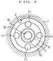
- Fig. 3 is a sectional view of III-III line in Fig. 1.
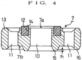
- Fig. 4 is a magnified detailed drawing of essential part (seat ring) in Fig. 1.
- Fig. 5 is a sectional view showing a modified example of seat ring.
- Fig. 6 is a sectional view showing other modified example of seat ring.
- Fig. 1 shows an open valve state of the diaphragm valve
- Fig. 2 shows a closed valve state.
- numeral 1 is a metallic valve body
- 2 is a valve compartment with a circular cross section formed in the valve body
- 3 is a valve operating compartment formed in the valve body
- 4 is a metallic stem acting as diaphragm manipulating means disposed retractably in the valve operating compartment
- 5 is a diaphragm holder disposed in the valve operating compartment
- 6 is a diaphragm made of circular thin metal plate such as stainless steel for shutting off between the valve compartment 2 and valve operating compartment
- 7 is a seat ring which is a valve seat forming member and is inserted in the valve compartment 2.
- valve body 1 As shown in Fig. 1, fluid passages 8 and 9 communicating with each other through the valve compartment 2 are formed. That is, the flow-in passage 8 and flow-out passage 9 have mouths 8a, 9a in the bottom wall 2a. In particular the flow-in passage mouth 8a is opened in the center of the bottom wall 2a.
- the diaphragm holder 5 is for pressing the peripheral edge of the diaphragm 6 to the seat ring 7 as shown in Fig. 1, and its pressing force is applied by tightening a nut member (not shown) threadedly mounted on the valve body 1.
- the seat ring 7 is formed in a metallic annular form and is made from stainless steel or the like, with its outside diameter roughly equal to the inside diameter of the valve compartment 2. Making relatively thin the thickness in the axial direction allows it to possess a certain elasticity or flexibility.
- the valve hole 10 which is the central hole of the seat ring 7 is overlaid on the flow-in passage mouth 8a.
- four communication holes 11 ... communicating with the flow-out passage mouth 9a are provided.
- the communication holes 11 ... are disposed at equal intervals around the valve hole 10.
- an annular valve seat 12 is projecting along the peripheral edge of the valve hole 10
- an annular diaphragm holding part 13 is projecting along the peripheral edge of the seat ring 7.
- the diaphragm holding part 13 holds the peripheral edge of the diaphragm 6, in cooperation with the diaphragm holder 5, by the pressing force of the diaphragm holder 5.
- the valve seat 12 is made from a synthetic resin material, and is buried and held in an annular groove 14 formed in the ring surface 7a, so that the surface area of the valve seat 12 may be as small as possible.
- This valve seat 12 is designed to contact with or depart from the central part of the diaphragm 6 by the extending and withdrawing operation of the stem 4, and the fluid passages 8, 9 are closed and opened by the contacting and departing action. That is, when the valve hole 10 is closed as the diaphragm 6 contacts with the valve seat 12, flow of fluid from the flow-in passage 8 into the flow-out passage 9 is inhibited (see Fig. 2).
- annular seal part 15 is projecting along the peripheral edge of the valve hole 10
- annular ring contact part 16 is projecting along the peripheral edge of the seat ring 7.
- the projection of the seal part 15 from the ring back side face 7b is, as shown in Fig. 4, set larger than the projection of the ring contact part 16 by a slight amount h (usually about 0.05 mm). Therefore, when the ring contact part 16 is pressed against the bottom wall 2a of the valve compartment 2 by the pressing force of the diaphragm holder 5, the seat ring 7 is bent with the seal part 15 acting as a flucrum. As a result, the seal part 15 is pressed against by the peripheral edge of the flow-in passage mouth 8a with an increased force.
- valve seat 12 is formed on the independent replaceable seat ring 7, as compared with the conventional diaphragm mentioned at the beginning, the maintainability is notably improved, and the life of the valve itself can be extended outstandingly.
- the seat ring 7 is formed as an independent member, fluid leak through between the seat ring 7 bottom wall 2a, i. e. so-called back leakage does not occur. The required valve function is exhibited sufficiently, and its practical value is extremely great.
- the ring contact part 16 is formed integrally with the seat ring 7.
- the ring contact part 16 may be separately made of synthetic resin material, and may be buried and held in an annular groove 17 formed in the ring back side 7b.
- the valve seat 12 may be made of synthetic resin material, and may be also buried and held in the ring surface 7a.
- valve seat 12 diaphragm holder 13, seal part 15, and ring contact part 16 may be formed integrally with the seat ring 7.
Landscapes
- Engineering & Computer Science (AREA)
- General Engineering & Computer Science (AREA)
- Mechanical Engineering (AREA)
- Lift Valve (AREA)
- Details Of Valves (AREA)
- Fluid-Driven Valves (AREA)
Applications Claiming Priority (2)
| Application Number | Priority Date | Filing Date | Title |
|---|---|---|---|
| JP131939/93 | 1993-06-02 | ||
| JP13193993A JP3280119B2 (ja) | 1993-06-02 | 1993-06-02 | ダイヤフラム弁 |
Publications (3)
| Publication Number | Publication Date |
|---|---|
| EP0627583A2 true EP0627583A2 (fr) | 1994-12-07 |
| EP0627583A3 EP0627583A3 (fr) | 1995-03-22 |
| EP0627583B1 EP0627583B1 (fr) | 1998-04-15 |
Family
ID=15069746
Family Applications (1)
| Application Number | Title | Priority Date | Filing Date |
|---|---|---|---|
| EP94303959A Expired - Lifetime EP0627583B1 (fr) | 1993-06-02 | 1994-06-02 | Soupape à diaphragme |
Country Status (8)
| Country | Link |
|---|---|
| US (1) | US5485984A (fr) |
| EP (1) | EP0627583B1 (fr) |
| JP (1) | JP3280119B2 (fr) |
| KR (1) | KR0153229B1 (fr) |
| CA (1) | CA2124781C (fr) |
| DE (1) | DE69409575T2 (fr) |
| SG (1) | SG45185A1 (fr) |
| TW (1) | TW298282U (fr) |
Cited By (7)
| Publication number | Priority date | Publication date | Assignee | Title |
|---|---|---|---|---|
| FR2759760A1 (fr) * | 1997-02-17 | 1998-08-21 | Asm France Sa | Vanne a membrane |
| FR2762891A1 (fr) * | 1997-05-02 | 1998-11-06 | Transfluid Sa | Vanne a membrane |
| EP1288544A3 (fr) * | 2001-08-24 | 2004-01-02 | Air Products And Chemicals, Inc. | Soupape à membrane pour des produits chimiques |
| EP0952505A4 (fr) * | 1997-08-15 | 2004-04-21 | Fujikin Kk | Regulateur debitmetrique a pression |
| EP1974826A1 (fr) * | 2007-03-24 | 2008-10-01 | Afa Polytek B.V. | Dispositif de distribution de liquides avec une vanne à membrane et procédé d'assemblage de la vanne |
| US7686280B2 (en) | 2005-12-28 | 2010-03-30 | Circor Instrumentation Technologies, Inc. | Removable valve seat member for diaphragm valve |
| EP2724060A4 (fr) * | 2011-06-24 | 2015-03-25 | Equilibar Llc | Régulateur de contre-pression doté d'un support de joint flottant |
Families Citing this family (42)
| Publication number | Priority date | Publication date | Assignee | Title |
|---|---|---|---|---|
| US5851004A (en) * | 1996-10-16 | 1998-12-22 | Parker-Hannifin Corporation | High pressure actuated metal seated diaphragm valve |
| US5730423A (en) * | 1996-10-16 | 1998-03-24 | Parker-Hannifin Corporation | All metal diaphragm valve |
| IL130567A (en) * | 1997-02-03 | 2002-04-21 | Swagelok Co | Diaphragm valve |
| US5909747A (en) * | 1998-04-03 | 1999-06-08 | American Meter Company | Radial flow diaphragm valve |
| JP3522535B2 (ja) * | 1998-05-29 | 2004-04-26 | 忠弘 大見 | 圧力式流量制御装置を備えたガス供給設備 |
| JP4700234B2 (ja) * | 2001-07-31 | 2011-06-15 | 株式会社フジキン | ダイヤフラム弁 |
| US20030042459A1 (en) * | 2001-08-29 | 2003-03-06 | Gregoire Roger J. | Unitary diaphragm and seat assembly |
| TW572164U (en) * | 2002-12-06 | 2004-01-11 | Ind Tech Res Inst | Diaphragm valve |
| CA2462342C (fr) * | 2003-03-28 | 2010-10-12 | Pn Ii, Inc. | Faitage incline universel |
| US20070045587A1 (en) * | 2003-04-14 | 2007-03-01 | Terrence Kolenc | Diaphragm valve seat |
| JP4211516B2 (ja) * | 2003-07-28 | 2009-01-21 | セイコーエプソン株式会社 | 流路弁及び同流路弁を備えた液体噴射装置 |
| US6988513B2 (en) * | 2003-10-27 | 2006-01-24 | Delaney Machinerie Inc. | Proportional valve |
| JP2005188672A (ja) * | 2003-12-26 | 2005-07-14 | Neriki:Kk | バルブ装置 |
| US6997440B2 (en) * | 2004-03-29 | 2006-02-14 | Tescom Corporation | Packless valve apparatus |
| US8414535B2 (en) * | 2007-04-12 | 2013-04-09 | Sterling Investments Lc | Miniature pump device and method |
| JP5140400B2 (ja) * | 2007-12-04 | 2013-02-06 | 株式会社ハムレット・モトヤマ・ジャパン | 弁構造 |
| EP2373374B1 (fr) * | 2008-10-22 | 2020-05-13 | Sterling Investments LC | Dispositif de pompe miniature équipé d'une vanne anti-écoulement libre |
| JP2010144765A (ja) * | 2008-12-16 | 2010-07-01 | Hamlet Motoyama Japan:Kk | ダイヤフラム弁 |
| US8844901B2 (en) * | 2009-03-27 | 2014-09-30 | Horiba Stec, Co., Ltd. | Flow control valve |
| US8245727B2 (en) * | 2009-06-26 | 2012-08-21 | Pamela Mooney, legal representative | Flow control valve and method of use |
| JP5153898B2 (ja) * | 2010-04-28 | 2013-02-27 | セントラル硝子株式会社 | ハロゲンガス又はハロゲン化合物ガスの充填容器用バルブ |
| JP5802532B2 (ja) * | 2011-12-05 | 2015-10-28 | 株式会社フジキン | ダイヤフラム弁およびダイヤフラム弁用シートホルダユニット |
| JP2013119877A (ja) * | 2011-12-06 | 2013-06-17 | Fujikin Inc | ダイヤフラム弁 |
| US9863542B2 (en) | 2013-02-01 | 2018-01-09 | Swagelok Company | Diaphragm valve with welded diaphragm seat carrier |
| JP6557224B2 (ja) * | 2013-07-09 | 2019-08-07 | デカ・プロダクツ・リミテッド・パートナーシップ | 弁装置およびシステム |
| JP6564593B2 (ja) * | 2015-03-25 | 2019-08-21 | 株式会社フジキン | ダイヤフラム弁 |
| CN108780332B (zh) * | 2016-02-29 | 2021-10-01 | 株式会社富士金 | 流量控制装置 |
| KR101708756B1 (ko) | 2016-09-21 | 2017-02-21 | 태광후지킨 주식회사 | 잠금형 다이어프램 밸브 |
| US10774938B2 (en) * | 2017-11-09 | 2020-09-15 | Swagelok Company | Diaphragm valve with metal seat |
| US11402029B2 (en) * | 2018-04-06 | 2022-08-02 | Fujikin Incorporated | Valve device, fluid control system, fluid control method, semiconductor manufacturing system, and semiconductor manufacturing method |
| JP7270990B2 (ja) * | 2018-07-24 | 2023-05-11 | 株式会社フジキン | バルブ装置、流体制御装置、流体制御方法、半導体製造装置及び半導体製造方法 |
| KR102503774B1 (ko) | 2018-07-31 | 2023-02-23 | 가부시키가이샤 후지킨 | 밸브 장치 |
| KR20210060657A (ko) * | 2018-10-26 | 2021-05-26 | 가부시키가이샤 후지킨 | 밸브 장치 및 가스 공급 시스템 |
| CN109326759B (zh) * | 2018-10-30 | 2022-03-18 | 广州小鹏汽车科技有限公司 | 压力调节装置及电池系统 |
| JP2020165476A (ja) * | 2019-03-29 | 2020-10-08 | 株式会社フジキン | ダイヤフラムバルブ |
| EP4077995B1 (fr) * | 2019-12-20 | 2025-04-02 | Swagelok Company | Corps de composant fluide avec passages de test de fuite |
| WO2021192753A1 (fr) * | 2020-03-26 | 2021-09-30 | 株式会社フジキン | Dispositif de soupape |
| KR102311898B1 (ko) | 2020-05-12 | 2021-10-13 | 주식회사 아스플로 | 잠금 기능을 갖는 밸브 및 잠금 기능을 갖는 밸브의 작동방법 |
| WO2022113748A1 (fr) * | 2020-11-26 | 2022-06-02 | イーグル工業株式会社 | Soupape |
| KR102673586B1 (ko) * | 2022-12-28 | 2024-06-12 | 주식회사 현대케피코 | 수소공급 밸브 및 조립방법 |
| KR102673585B1 (ko) * | 2022-12-28 | 2024-06-12 | 주식회사 현대케피코 | 교체 가능한 밸브시트가 적용된 수소공급 밸브 |
| JP2025014385A (ja) * | 2023-07-18 | 2025-01-30 | Ckd株式会社 | 流体制御弁 |
Family Cites Families (13)
| Publication number | Priority date | Publication date | Assignee | Title |
|---|---|---|---|---|
| GB320778A (en) * | 1928-10-26 | 1929-10-24 | Philip Keith Saunders | Improvements in and means for operating diaphragm valves |
| US2856148A (en) * | 1952-02-08 | 1958-10-14 | Vickers Electrical Co Ltd | Valve assembly |
| GB1462176A (en) * | 1973-07-27 | 1977-01-19 | Fordham Pressings Ltd | Valves |
| DE3444865A1 (de) * | 1984-12-08 | 1986-06-12 | Regel + Meßtechnik GmbH Regler- und Anlagenbau für Gas-Druckregelung, 3500 Kassel | Druckmittelbetaetigtes membranventil |
| JPS63115970A (ja) * | 1986-10-31 | 1988-05-20 | Motoyama Seisakusho:Kk | ダイヤフラム弁 |
| US4741510A (en) * | 1987-09-04 | 1988-05-03 | Baumann Hans D | Flow control valve |
| US4846215A (en) * | 1988-06-07 | 1989-07-11 | Marathon Oil Company | Back pressure regulator |
| JPH03115970A (ja) * | 1989-09-29 | 1991-05-16 | Ngk Insulators Ltd | ボールの自動超音波探傷検査装置 |
| JPH03153974A (ja) * | 1989-11-08 | 1991-07-01 | Moon Star Co | バルブシール部にシールリングを嵌合する方法 |
| JPH086828B2 (ja) * | 1991-08-09 | 1996-01-29 | 株式会社ベンカン | メタルダイヤフラム弁 |
| US5295662A (en) * | 1991-08-26 | 1994-03-22 | Masako Kiyohara | Fluid flow-controller with improved diaphragm |
| JP2927582B2 (ja) * | 1991-08-26 | 1999-07-28 | 清原 まさ子 | 制御器 |
| US5215286A (en) * | 1992-05-26 | 1993-06-01 | Nupro Company | High pressure diaphragm valve |
-
1993
- 1993-06-02 JP JP13193993A patent/JP3280119B2/ja not_active Expired - Fee Related
-
1994
- 1994-05-25 KR KR1019940011352A patent/KR0153229B1/ko not_active Expired - Fee Related
- 1994-05-27 US US08/250,609 patent/US5485984A/en not_active Expired - Lifetime
- 1994-05-31 CA CA002124781A patent/CA2124781C/fr not_active Expired - Fee Related
- 1994-06-02 EP EP94303959A patent/EP0627583B1/fr not_active Expired - Lifetime
- 1994-06-02 SG SG1996001075A patent/SG45185A1/en unknown
- 1994-06-02 DE DE69409575T patent/DE69409575T2/de not_active Expired - Fee Related
- 1994-07-26 TW TW085204746U patent/TW298282U/zh unknown
Cited By (12)
| Publication number | Priority date | Publication date | Assignee | Title |
|---|---|---|---|---|
| FR2759760A1 (fr) * | 1997-02-17 | 1998-08-21 | Asm France Sa | Vanne a membrane |
| EP0863341A1 (fr) | 1997-02-17 | 1998-09-09 | Qualiflow S.A. | Vanne à membrane |
| FR2762891A1 (fr) * | 1997-05-02 | 1998-11-06 | Transfluid Sa | Vanne a membrane |
| EP0952505A4 (fr) * | 1997-08-15 | 2004-04-21 | Fujikin Kk | Regulateur debitmetrique a pression |
| EP1288544A3 (fr) * | 2001-08-24 | 2004-01-02 | Air Products And Chemicals, Inc. | Soupape à membrane pour des produits chimiques |
| US7686280B2 (en) | 2005-12-28 | 2010-03-30 | Circor Instrumentation Technologies, Inc. | Removable valve seat member for diaphragm valve |
| EP1974826A1 (fr) * | 2007-03-24 | 2008-10-01 | Afa Polytek B.V. | Dispositif de distribution de liquides avec une vanne à membrane et procédé d'assemblage de la vanne |
| WO2008116656A1 (fr) * | 2007-03-24 | 2008-10-02 | Afa Polytek B.V. | Dispositif de distribution de liquide avec soupape à membrane et procédé d'assemblage de la soupape |
| US8256648B2 (en) | 2007-03-24 | 2012-09-04 | Afa Polytek B.V. | Precompression system for a liquid dispensing device and method of assembling such precompressed system |
| US9586222B2 (en) | 2007-03-24 | 2017-03-07 | Afa Polytek B.V. | Precompression system for a liquid dispensing device and method of assembling such precompressed system |
| EA029857B1 (ru) * | 2007-03-24 | 2018-05-31 | Афа Политек Б.В. | Устройство дозирования жидкости, система предварительного сжатия для такого устройства и способ ее сборки |
| EP2724060A4 (fr) * | 2011-06-24 | 2015-03-25 | Equilibar Llc | Régulateur de contre-pression doté d'un support de joint flottant |
Also Published As
| Publication number | Publication date |
|---|---|
| SG45185A1 (en) | 1998-01-16 |
| DE69409575T2 (de) | 1998-12-24 |
| JP3280119B2 (ja) | 2002-04-30 |
| TW298282U (en) | 1997-02-11 |
| KR0153229B1 (ko) | 1999-02-18 |
| CA2124781C (fr) | 1998-12-22 |
| EP0627583A3 (fr) | 1995-03-22 |
| EP0627583B1 (fr) | 1998-04-15 |
| CA2124781A1 (fr) | 1994-12-03 |
| JPH06341560A (ja) | 1994-12-13 |
| US5485984A (en) | 1996-01-23 |
| KR950001154A (ko) | 1995-01-03 |
| DE69409575D1 (de) | 1998-05-20 |
Similar Documents
| Publication | Publication Date | Title |
|---|---|---|
| EP0627583A2 (fr) | Soupape à diaphragme | |
| EP3320241B1 (fr) | Bonnet de soupape et vanne de régulation comportant celui-ci | |
| EP1281898B1 (fr) | Soupape à membrane | |
| EP1053431B1 (fr) | Vanne electromagnetique comportant des canaux a fluide abritant des tubes rigides, menages dans le siege, et une membrane d'etancheite souple | |
| US6755389B2 (en) | Flow regulation valve | |
| US5730423A (en) | All metal diaphragm valve | |
| EP2167853B1 (fr) | Vanne à membrane à haute pression pourvue d'un ensemble support échangeable | |
| JP2006090386A (ja) | ダイヤフラムバルブ | |
| CA2445829A1 (fr) | Robinet de sectionnement avec membrane, actionne par pression | |
| KR19990067667A (ko) | 미소한 제어 유량을 조절하는 유량전송수단으로 작동되는 유량밸브 | |
| IE57114B1 (en) | Improvements in and relating to valve seals | |
| KR19990078376A (ko) | 유체 커플링 | |
| EP1114955B1 (fr) | Soupape à deux voies | |
| US3069129A (en) | Valve construction having fluid pressure and spring bias seals | |
| US4277047A (en) | Metallic sealing device for valve | |
| US20240240726A1 (en) | Diaphragm valve with actuator bearing element | |
| US4817914A (en) | Electromagnetic valve assembly | |
| EP1114954A2 (fr) | Soupape à deux voies | |
| KR20170025886A (ko) | 볼밸브 | |
| JP3095983B2 (ja) | パイロット式ダイアフラム弁 | |
| US4762142A (en) | Metered float controlled valve | |
| GB2081843A (en) | Fluid valve means | |
| CN120936829A (zh) | 用于保持车辆空气悬架中的残余压力的阀 | |
| HK1034109B (en) | Solenoid valve having hard tube fluid channels in valve seat and flexible sealing diaphragm | |
| GB2041501A (en) | Pilot-assisted fluid flow control valve |
Legal Events
| Date | Code | Title | Description |
|---|---|---|---|
| PUAI | Public reference made under article 153(3) epc to a published international application that has entered the european phase |
Free format text: ORIGINAL CODE: 0009012 |
|
| 17P | Request for examination filed |
Effective date: 19940709 |
|
| AK | Designated contracting states |
Kind code of ref document: A2 Designated state(s): DE FR GB IT NL |
|
| PUAL | Search report despatched |
Free format text: ORIGINAL CODE: 0009013 |
|
| AK | Designated contracting states |
Kind code of ref document: A3 Designated state(s): DE FR GB IT NL |
|
| 17Q | First examination report despatched |
Effective date: 19960524 |
|
| GRAG | Despatch of communication of intention to grant |
Free format text: ORIGINAL CODE: EPIDOS AGRA |
|
| GRAG | Despatch of communication of intention to grant |
Free format text: ORIGINAL CODE: EPIDOS AGRA |
|
| GRAH | Despatch of communication of intention to grant a patent |
Free format text: ORIGINAL CODE: EPIDOS IGRA |
|
| GRAH | Despatch of communication of intention to grant a patent |
Free format text: ORIGINAL CODE: EPIDOS IGRA |
|
| GRAA | (expected) grant |
Free format text: ORIGINAL CODE: 0009210 |
|
| AK | Designated contracting states |
Kind code of ref document: B1 Designated state(s): DE FR GB IT NL |
|
| ITF | It: translation for a ep patent filed | ||
| REF | Corresponds to: |
Ref document number: 69409575 Country of ref document: DE Date of ref document: 19980520 |
|
| ET | Fr: translation filed | ||
| PLBE | No opposition filed within time limit |
Free format text: ORIGINAL CODE: 0009261 |
|
| STAA | Information on the status of an ep patent application or granted ep patent |
Free format text: STATUS: NO OPPOSITION FILED WITHIN TIME LIMIT |
|
| 26N | No opposition filed | ||
| REG | Reference to a national code |
Ref country code: GB Ref legal event code: IF02 |
|
| PGFP | Annual fee paid to national office [announced via postgrant information from national office to epo] |
Ref country code: IT Payment date: 20080621 Year of fee payment: 15 |
|
| PGFP | Annual fee paid to national office [announced via postgrant information from national office to epo] |
Ref country code: NL Payment date: 20080626 Year of fee payment: 15 Ref country code: DE Payment date: 20080829 Year of fee payment: 15 |
|
| PGFP | Annual fee paid to national office [announced via postgrant information from national office to epo] |
Ref country code: FR Payment date: 20080627 Year of fee payment: 15 |
|
| PGFP | Annual fee paid to national office [announced via postgrant information from national office to epo] |
Ref country code: GB Payment date: 20080630 Year of fee payment: 15 |
|
| GBPC | Gb: european patent ceased through non-payment of renewal fee |
Effective date: 20090602 |
|
| NLV4 | Nl: lapsed or anulled due to non-payment of the annual fee |
Effective date: 20100101 |
|
| REG | Reference to a national code |
Ref country code: FR Ref legal event code: ST Effective date: 20100226 |
|
| PG25 | Lapsed in a contracting state [announced via postgrant information from national office to epo] |
Ref country code: FR Free format text: LAPSE BECAUSE OF NON-PAYMENT OF DUE FEES Effective date: 20090630 |
|
| PG25 | Lapsed in a contracting state [announced via postgrant information from national office to epo] |
Ref country code: GB Free format text: LAPSE BECAUSE OF NON-PAYMENT OF DUE FEES Effective date: 20090602 |
|
| PG25 | Lapsed in a contracting state [announced via postgrant information from national office to epo] |
Ref country code: DE Free format text: LAPSE BECAUSE OF NON-PAYMENT OF DUE FEES Effective date: 20100101 |
|
| PG25 | Lapsed in a contracting state [announced via postgrant information from national office to epo] |
Ref country code: NL Free format text: LAPSE BECAUSE OF NON-PAYMENT OF DUE FEES Effective date: 20100101 |
|
| PG25 | Lapsed in a contracting state [announced via postgrant information from national office to epo] |
Ref country code: IT Free format text: LAPSE BECAUSE OF NON-PAYMENT OF DUE FEES Effective date: 20090602 |