EP0627701B1 - Bildverarbeitungsverfahren und Vorrichtung zur Dokumentenanalyse - Google Patents
Bildverarbeitungsverfahren und Vorrichtung zur Dokumentenanalyse Download PDFInfo
- Publication number
- EP0627701B1 EP0627701B1 EP94303891A EP94303891A EP0627701B1 EP 0627701 B1 EP0627701 B1 EP 0627701B1 EP 94303891 A EP94303891 A EP 94303891A EP 94303891 A EP94303891 A EP 94303891A EP 0627701 B1 EP0627701 B1 EP 0627701B1
- Authority
- EP
- European Patent Office
- Prior art keywords
- character image
- image block
- image blocks
- blocks
- image
- Prior art date
- Legal status (The legal status is an assumption and is not a legal conclusion. Google has not performed a legal analysis and makes no representation as to the accuracy of the status listed.)
- Expired - Lifetime
Links
Images









Classifications
-
- G—PHYSICS
- G06—COMPUTING OR CALCULATING; COUNTING
- G06T—IMAGE DATA PROCESSING OR GENERATION, IN GENERAL
- G06T11/00—Two-dimensional [2D] image generation
- G06T11/60—Creating or editing images; Combining images with text
Definitions
- the present invention relates to an image processing method and an image processing apparatus for appointing an area in a supplied image.
- appoint a partial area of an image formed by a conventional image processing apparatus of the foregoing type
- the method comprises the steps of displaying an image on a display, and acquiring coordinates of the diagonals of an area in the image to be appointed by using a pointing device, such as a mouse.
- the foregoing method comprises the step of sequentially appointing vertexes of an appointed polygon.
- an area in the form of a further complicated shape can be appointed.
- a character image 2101 which is a portion of a document
- a table image 2102 an image 2103 of a graph and its title
- a portion 2104 of a half tone image such as a photograph.
- the appointment of an image can be considered as a selection of pixels, there are many cases that the minimum unit of an appointed area does not need to be the pixel unit.
- one character image unit is the minimum unit of the character image 2101
- the line and the array or cell unit is the same as the table image 2102
- the graph portion and the title portion are the same as the image 2103 of the graph and its title.
- the conventional image processing apparatus enables only the appointment in a pixel unit to be performed, and accordingly the foregoing problems arise.
- EP-A-0496531 discloses a technique of analysing the layout of a document and labelling character strings using separators and sub-separators.
- a document entitled Catch Word Pro-User's Guide by Logitech; Macintosh version, 1993, CA, USA, pages 17-26 discloses a technique for automatically generating selection boxes surrounding a header and a column from a scanned document.
- EP-A-0439951 discloses a text editing system that is capable of operating on text present in an image pixel-based format.
- the system includes character and word segmentation steps and a data structure that provides the necessary links between the segmented characters and words.
- the present invention is directed to overcoming the problems experienced with the foregoing conventional technology, and therefore a concern of the present invention is to provide an image processing method and an apparatus which are capable of easily appointing a portion of a supplied image with a decreased number of operations or by easily making a subject image visible.
- the area appointment of a portion of an image can be performed in image block units, and therefore the area appointment operation can easily be performed.
- the area appointment of a portion of an image can be performed in image block units, and therefore the area appointment operation can easily be performed.
- the area appointment when an area of a portion of an image is appointed, the area appointment is performed in image block units. Therefore, the area appointment operation can easily be performed, the operation of appointing the area can efficiently be performed, the area appointment can accurately be completed, and therefore an effect can be obtained in that an efficient appointed area can be obtained.
- an image, an area of which has been appointed is subjected to another process, the spaces between lines and between characters are not included in the appointed areas in, for example, an optical character reader (an OCR). Therefore, effects can be obtained in that the time taken to complete transfer can be shortened when an image is transferred and that the capacity required to store an image can be saved when the image is stored in a memory or the like.
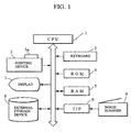
- Fig. 1 is a block diagram which illustrates the structure of an image processing apparatus.
- a CPU (Central Processing Unit) 1 controls all operations of the image processing apparatus to be performed in accordance with a control program stored in a ROM (Read Only Memory) 4 to be described later.
- the following units are connected to CPU 1 through control lines: a keyboard (a character image input means) 2, a pointing device 3, the ROM 4, a RAM (Random Access Memory) 5, an I/F (interface) 6, a display 7, such as a CRT or a liquid crystal display, and an external storage unit 8.
- the keyboard 2 has a plurality of keys and is used to input/modify a character image.
- the pointing device 3 comprises a mouse or the like having a depression button 3a which is operated when an image, or an area in the image displayed on the display 7 is appointed.
- the ROM 4 stores a program or the like for controlling the processes to be performed by the image processing apparatus, for example, processes shown in a flow chart to be described later, and to be performed by CPU 1.
- An image scanner 9 for reading images is connected to the I/F 6.
- the display 7 displays a supplied image or the like.
- the external storage unit 8 comprises a magnetic disk or the like to record various data items.
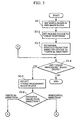
- FIG. 2 is a flow chart which illustrates a procedure of controlling the image area appointing operation.
- Figs. 7A-7C illustrate states of the display 7 on which the process for appointing an area of the image is being performed.
- step S2-1 shown in Fig. 2 image information is read by the image scanner 9 or images previously stored in the external storage unit 8 are read.
- a state of the display 7 at this time is shown in Fig. 7A.
- CPU 1 divides the supplied image into image blocks.
- a state of the display 7 at this time is shown in Fig. 7B.
- reference numeral 701 represents one image block. Although the divided image blocks are displayed on the display 7 in this embodiment, the display may be omitted.
- the display of the image block in step S2-1 may be omitted but the image block may be displayed on the display 7 when the process in step S2-2 is completed.
- step S2-3 a point on the image at which the depression button 3a of the pointing device 3 is depressed is set to a start point of the area appointment.
- the CPU 1 acquires the coordinates of the start point. Then, in a state where the depression button 3a of the pointing device 3 is being depressed, the pointing device 3 is moved to an end point of the appointment. When the depression of the depression button 3a is released, the operation of appointing the area is completed.
- step S2-4 CPU 1 acquires the position of the pointing device 3.
- step S2-5 CPU 1 selects an appointed image block from image blocks, the appointed image block including the appointment end position which is the position of the pointing device 3 acquired in step S2-4.
- FIG. 7C A state of the display 7, on which the area is being appointed, is shown in Fig. 7C.
- reference numeral 702 represents a rectangular appoint range having, at its diagonal positions, the area appointment start position and the area appointment completion position.
- Reference numeral 703 represents one appointed image block which is inversely displayed.
- step S2-5 After CPU 1 selects, in step S2-5, an appointed image block from image blocks, the appointed image block including the appointment end position which is the position of the pointing device 3 acquired in step S2-4, CPU 1, in step S2-6, discriminates whether or not the appointment operation has been completed. If the depression of the depression button 3a of the pointing device 3 has been released, CPU 1 discriminates that the appointment operation has been completed. Thus, the finally acquired position is set to the final appointed end position and the processing operation in this embodiment is completed. If the depression of the depression button 3a has not been released, a discrimination is made that the appointment operation has not been completed, and the flow returns to step S2-4.
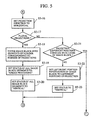
- step S2-2 An example of the process to be executed in step S2-2 shown in Fig. 2, that is, a process of dividing an image into image blocks will now be described with reference to a flow chart shown in Figs. 3 to 5.
- An image to be processed in step S3-1 shown in Fig. 3 is treated as one image block.
- the image block has, as information, "process status”, "pervious projection direction status” and the position of the image block, with each state being allowed to have states “under processing", “end of the process", "vertical direction” and "horizontal direction”.
- step S3-2 CPU 1 initializes the "process status" of the set image block to "under processing", and initializes the "previous projection direction status" to the "horizontal direction” in step S3-3. It should be noted that the "previous projection direction status" may be initialized to the "horizontal-direction”. The necessity lies in the initialization.
- step S3-4 CPU 1 searches an image block, the "process status" of which is the "under processing” (discriminates whether or not any image block which is "under processing” exists). If no image block of the foregoing type exists, this processing operation is ended. If the image block is present, the flow proceeds to step S3-5. In step S3-5 CPU 1 selects one image block, the "process status" of which is the "under processing”. In step S3-6 CPU 1 discriminates whether or not the "previous projection direction status" is the "vertical direction" or the "horizontal direction”. If it is in the "vertical direction”, the flow proceeds to step S3-7 shown in Fig. 4. If it is in the "horizontal direction", the flow proceeds to step S3-16 shown in Fig. 5.
- step S3-7 CPU 1 sets the projection direction to horizontal.
- step S3-8 CPU 1 discriminates whether or not plural projections exist. If plural projections exist, CPU 1, in step S3-9, divides the image blocks in a horizontal direction into the number of the projections. At this time, the position information of each image block is set in such a way that the upper and lower positions of the projection are used as the upper and lower coordinates and that the right and left positions of the image block, which has not been divided, are used as the right and left coordinates.
- step S3-10 sets all "process status” to "under processing”
- step S3-11 CPU 1 sets all "previous projection direction status” of the image blocks, which have been divided in step S3-11, to "horizontal direction”. Then, the flow returns to step S3-4 shown in Fig. 3.
- step S3-8 CPU 1 discriminates in step S3-12 whether or not the upper and lower positions of the projection and the upper and lower positions of the image block coincide with one another. If they coincide with one another, the flow proceeds to step S3-15 so that CPU 1 sets the "process status" to the "end of the process". If a discrimination has been made in step S3-12 that the upper and lower positions of the projection and the upper and lower positions of the image block do not coincide with one another, CPU 1 changes the upper and lower position information of the image block to the upper and lower positions of the projection. In step S3-14 CPU 1 sets the "previous projection direction status" to the "horizontal direction", and then the flow returns to step S3-4 shown in Fig. 3.
- step S3-16 CPU 1 acquires the-projection in the vertical direction.
- step S3-17 CPU 1 discriminates whether or not plural projections exist. If plural projections exist, CPU 1 divides the image block in the vertical direction into the number of the projections. At this time, the position information of each image block is set in such a way that the upper and lower positions of the projection are used as the upper and lower coordinates and that the right and left positions of the image block, which has not been divided, are used as the right and left coordinates. Then, in step S3-19 CPU 1 sets all "process status" of the divided image block to "under processing". In step S3-20 CPU 1 sets all "previous projection direction status" of the image block, which has been divided, to the "vertical direction”. Then, the flow returns to step S3-4 shown in Fig. 3.
- step S3-17 CPU 1 discriminates, in step S3-21, whether or not the right and left positions of the projection and the right and left positions of the image block coincide with one another. If they coincide with one another, the flow proceeds to step S3-15 shown in Fig. 4 so that CPU 1 sets the "process status" to the "completion of the process". If a discrimination has been made in step S3-21 that the right and left positions of the projection and the right and left positions of the image block do not coincide with one another, CPU 1 changes right and left position information items of the image block to the right and left positions of the projection in step S3-22. In step S3-23 CPU 1 set the "previous projection direction status" to the "vertical direction”. Then, the flow returns to step S3-4 shown in Fig. 3.
- Fig. 8A illustrates the display 7 in a state where the process has not yet started, the foregoing state being set as a first image block.
- one projection can be acquired in the horizontal direction so that an image block 801 is obtained as shown in Fig. 8B.
- a vertical projection of the image block 801 is acquired so that the image block 801 is divided into two image blocks 802 and 803 as shown in Fig. 8C.
- an image block 804 can be obtained as shown in Fig. 8D. Since the right and left positions of the vertical projection of the image block 804 coincides with the right and left positions of the projection, the status is set to "completion of the process".
- the residual image block 803 is subjected to a similar process to which the image block 802 has been subjected. As a result, a multiplicity of image blocks as shown in Fig. 8E can be obtained.
- step S2-5 shown in Fig. 2 that is, an example of a process for selecting an appointed image block will now be described with reference to a flow chart shown in Fig. 6.
- the axis of coordinates are arranged in such a way that the left upper position is set to the origin, the x-coordinate is set toward the right and y-coordinate is set toward the bottom.
- the left upper coordinates of a rectangular region appointed in step S6-1 are set to (X1, Y1) and the right lower coordinates of the same are set to (X2, Y2).
- step S6-2 the image blocks are obtained in step S6-2, and are arranged in the order of processing, and the leading image block is set to an image block of interest in step S6-3. Then, the following process is performed starting from the foregoing image block.
- step S6-4 a determination is made as to whether or not an image block of interest to be processed exists. If it does not exist, this process is ended. If it exists, the flow proceeds to step S6-5.
- step S6-5 the left upper coordinates of the image block of interest are set to (x1, y1) and the right lower coordinates of the same are set to (x2, y2). If the left upper point (x1, y1) of the image block of interest is, in next step S6-6, present at a right lower position with respect to the left upper point (X1, Y1) of the appointed rectangular region or if the right lower point (x2, y2) of the image block of interest is, in step S6-7, present at a left upper point with respect to the right lower point (X2, Y2), the image block of interest is set to the appointed image block in step S6-8. Then, the order of the image block of interest is advanced by one in step S6-9, and the flow returns to step S6-4. As a result of the foregoing process, an appointed image block can be selected from a plurality of image blocks.
- step S6-6 If the left upper point (x1, y1) of the image block of interest is not, in step S6-6, present at a right lower position with respect to the left upper point (X1, Y1) of the appointed rectangular region or if the right lower point (x2, y2) of the image block of interest is not, in step S6-7, present at a left upper point with respect to the right lower point (X2, Y2), step S6-8 is not executed, and the flow proceeds to step S6-9.
- the image block in the form of a circumscribed rectangle can be obtained by cutting and therefore only required image blocks can easily be selected.
- this embodiment has a structure in which the appointed image block can be set only in a case where the overall portion of the image block is set to the appointed area, another structure may be employed in which an appointed image block can be set if a portion of the image block is set to the appointed area.
- FIG. 9 Another example of image processing apparatus will now be described with reference to Figs. 9, 10A and 10B.
- the foregoing image block dividing method according to the apparatus of Fig 1 is able to process, with a simple procedure and a light load required, an image, such as a document image having image blocks arranged vertically or horizontally, it sometimes encounters an impossibility of sufficiently finely dividing image blocks, that are arranged in a complicated manner.
- This apparatus is arranged to be capable of finely dividing image blocks even if they are arranged in a complicated manner.
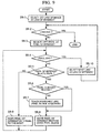
- Fig. 9 is a flow chart which illustrates a procedure of performing control of a process of dividing an image block in an image processing apparatus according to this second example.
- Figs. 10A and 10B illustrate states of a display which are performed in the image block dividing process.
- step S9-1 shown in Fig. 9 in order to start processing at the first line of an image, the first line is selected as a line of interest.
- step S9-2 whether or not the line has been completed is discriminated. If it has been completed, this process is ended, and if it has not been completed the flow proceeds to step S9-3.
- step S9-3 a left pixel to the line of interest to be processed is set as a pixel of interest, and observation is made from the left portion to the right portion.
- step S9-4 whether or not the pixel is finished (whether or not the pixel of interest exists) is discriminated. If the pixel is finished, the next line is set to a line of interest in step S9-10, and then the flow returns to step S9-2 in which the next line is processed. If the pixel is not finished, the flow proceeds to step S9-5.
- step S9-5 whether or not the pixel of interest is a black pixel is discriminated. If the pixel of interest is not a black pixel but the same is a white pixel, the pixel of interest is shifted to the right by one pixel in step S9-9. Then, the flow returns to step S9-4. If the pixel is a black pixel, a discrimination is, in step S9-6, made whether or not the boundary line of the pixel has been traced. If the pixel is not the traced pixel, the boundary is, in step S9-7, traced so that an image block is obtained. In step S9-8, the image block is skipped over so that the pixel of interest is shifted, and the flow returns to step S9-4.
- step S9-6 If a discrimination has been made in step S9-6 that the pixel is the traced pixel, step S9-7 is not executed, and the flow proceeds to step S9-8.
- reference numeral 101 represents a present line of interest, and illustrates a state where a black pixel 102 has been found. Since the black pixel 102 is in a state where its boundary has not been traced, a boundary line 103 is obtained. When the boundary line 103 has been returned to the original black pixel 102, tracing is dismissed and it is set to an image block. In order to return to a process for searching a black pixel, the pixel of interest is shifted to the right. In this state, attention is paid to a fact that the point is not a point on the obtained boundary line 103 at the time of determining a next pixel 104.
- image blocks can be obtained in units of boundary lines.
- the black pixel is, in this embodiment, searched from the upper line to the lower line and from the left portion toward the right portion, the searching method is not limited to this.
- a pre-treatment such as an image thinning process, may be performed before the black pixel is searched.
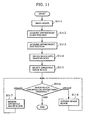
- FIG. 11 is a flow chart which illustrates a procedure of controlling a process to be performed by the image processing apparatus according to this third example.
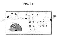
- Fig. 12 illustrates a state of the display which is performing the process.
- step S11-1 shown in Fig. 11 image information is read by the image scanner 9 or images previously stored in the external storage unit 8 are read.
- a state of the display 7 at this time is similar to that realized in the first embodiment shown in Fig. 7.
- step S11-2 a point on the image, at which the depression button 3a of the pointing device 3 is depressed, is set to the start point of the area appointment.
- CPU 1 acquires the coordinates of the start point
- step S11-3 a point on the image, at which the depression button 3a of the pointing device 3 is again depressed, is set to the final point of the area appointment.
- CPU 1 then acquires the coordinates of the start point.
- Fig. 12 is a diagram which illustrates the state of the display 7 on which an appointment start position 121 and an appointment completion position 122 are displayed.
- step S11-4 an image block is taken from an image included in a rectangular appointed area, the diagonal positions of which are set to the appointment start position and the appointment completion position.
- the taken image block is, as an appointed image block, selected in step S11-5. Then, the image block is appointed, dismissed or completed in step S11-6.
- the pointing device 3 When the image block is dismissed, the pointing device 3 is brought to the image block already appointed in step S11-7 and then the depression button 3a of the pointing device 3 is depressed so that the appointment is dismissed. After the appointment has been dismissed, the flow returns to step S11-6.
- the pointing device 3 When an image block is appointed, the pointing device 3 is brought to a position adjacent to the image block dismissed from the appointment in step S11-8 and the depression button 3a of the pointing device 3 is depressed to again appoint the image block.
- the process is ended.
- the process for dividing the image into image blocks is performed in a portion of the image in place of the overall portion of the image. Therefore, the time taken to complete the process can be shortened. Since appointment and dismissal for each image block can be enabled, appointment can be finely performed.
- Fig. 13 is a flow chart which illustrates the procedure of controlling a process of dividing an image block to be performed by an image processing apparatus according to this embodiment.
- Figs. 16 to 18 are explanatory views which illustrate the image block dividing process and the process of an image block to be performed by the apparatus according to this embodiment. Also in this embodiment, an assumption is made that the document direction of the document image has been detected prior to performing the process according to this embodiment.
- step S13-1 shown in Fig. 13 a projection is acquired in the direction of lines of the document.
- a projection 165 shown in Fig. 16 is obtained.
- step S13-2 lines are extracted so that a linear rectangle 166 is obtained.
- step S13-3 the obtained start and end coordinates of the line are stored.
- reference numeral 161 represents line start coordinates of a first line
- 162 represents line end coordinates of the first line
- 163 represents line start coordinates of a second line
- 164 represents line end coordinates of the second line.
- step S13-4 a projection for each line is acquired in a direction (a vertical direction) perpendicular to the direction of the line so that a projection 177 shown in Fig. 17 is obtained.
- step S13-5 an image block (a character block) 178 shown in Fig. 17 is obtained.
- step S13-6 the start coordinates and end coordinates of the image block are stored.
- reference numeral 171 represents an image block start coordinates of a first character of a line
- 172 represents image block end coordinate of the first character of the line
- 173 represents image block start coordinates of a second character of the line
- 174 represents image block end coordinates of the second character of the line.
- the thus-obtained image blocks are arranged in an array starting from the first line in step S13-7, and the process is ended.
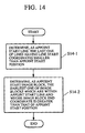
- Fig. 14 is a flow chart which illustrates the procedure of controlling a process for searching an appointment area start image block.
- step S14-1 shown in Fig. 14 a last line of lines of a type having line start coordinates which are smaller than the appointment start position is determined as the appointment start line.
- step S14-2 the earliest one of the image blocks which are within an appoint start line and whose image block end coordinate is greater than that of appoint start position is determined as the appointment area start image block. Then, this process is completed.
- Fig. 15 is a flow chart which illustrates the procedure of controlling a process for searching the appointment area completion image block.
- step S15-1 shown in Fig. 15 a last line of lines having a line start coordinate smaller than the appointment end position is determined to be the appointment end line.
- step S15-2 a last image block of those of the appointment end line and whose image block start coordinate is smaller than the appointment end position is determined to be the appointment area end image block. Then, this process is completed.
- appointment area start image block and the appointment area end image block are obtained, they are searched from the image block array obtained in step S13-7 shown in Fig. 13 so that all image blocks present between the appointment area start image block and the appointment area end image block are determined to be appointed image blocks.
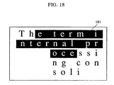
- the display of the appointed image blocks may be performed variously, for example, the inverse display of the image blocks employed in the foregoing embodiments and display for changing the color.
- a display shown in Fig. 18 may be employed in which the overall body of a rectangular form 181 between the appointment area start image block and the appointment area end image block is inversely displayed.
- a portion of a document image can be appointed without collapse of the sentences.
- the rule for selecting the image blocks is not limited to the method according to this embodiment.
- the present invention can be implemented by a computer program operating on a standard desk top computer.
- An aspect of the present invention thus provides a storage medium storing processor implementable instructions for controlling a processor to carry out the method as hereinabove described.
Landscapes
- Physics & Mathematics (AREA)
- General Physics & Mathematics (AREA)
- Engineering & Computer Science (AREA)
- Theoretical Computer Science (AREA)
- Processing Or Creating Images (AREA)
- Character Input (AREA)
- Image Processing (AREA)
- Document Processing Apparatus (AREA)
Claims (28)
- Bildverarbeitungsverfahren, mit den Verfahrensschritten:einem Bildblockeinteilschritt (S13-1 bis S13-5) des Einteilens einer Vielzahl von Zeichenbildblöcken aus einem gelesenen Bild; undeinem Speicherschritt (S13-6 und S13-7) des Speicherns einer Vielzahl von Koordinatendaten der Zeichenbildblöcke, die die Positionen eines jeden eingeteilten Zeichenbildblockes im gelesenen Bild in der Reihenfolge der Anordnung der Zeichenbildblöcke spezifiziert; gekennzeichnet durcheinen Festlegeschritt (Zeigereinrichtung 3, S14-1, S14-2, S15-1, S15-2) zum Festlegen zweiter willkürlicher Koordinaten auf einem gelesenen und auf einer Anzeige angezeigtem Bild;einem Zeichenbildblock-Auswahlschritt (S14-1, S14-2, S15-1, S15-2) zum Auswählen eines Startzeichenbildblockes und eines Endzeichenbildblockes durch Vergleichen der willkürlich festgelegten Koordinaten mit der Vielzahl von Koordinatendaten von im Speicherschritt gespeicherten Zeichenbildblöcken und Auswählen von Zeichenbildblöcken, die sich zwischen dem Startund den Endzeichenbildblock aus der Vielzahl von Zeichenbildblöcken befinden, auf der Grundlage der Reihenfolge der Anordnung von Zeichenbildblöcken; undeinem Ausgabeschritt des Ausgebens eines Teils des Bildes, das über die Vielzahl ausgewählter Zeichenbildblöcke verfügt.
- Verfahren nach Anspruch 1, bei dem der Festlegeschritt eine Vielzahl von Festlegeprozessen umfaßt und des weiteren einen Umschaltprozeßschritt enthält, um die im Festlegeschritt verwendeten Festlegeprozesse umzuschalten.
- Verfahren nach Anspruch 1 oder 2, bei dem der Startzeichenblock aus der Bildblockanordnung gemäß einer der beiden festgelegten willkürlichen Koordinaten ausgewählt wird, wenn die geteilten Zeichenbildblöcke in Bildblockanordnung sind, und der Endzeichenbildblock wird ausgewählt aus der Bildblockanordnung gemäß dem anderen der beiden festgelegten willkürlichen Koordinaten, und die Zeichenbildblöcke, die sich zwischen dem Start- und Endzeichenbildblock befinden, werden auf der Grundlage der Reihenfolge ausgewählt, in der die Zeichenbildblöcke in der Bildblockanordnung im Auswahlschritt für die Zeichenbildblöcke angeordnet waren.
- Verfahren nach Anspruch 1, bei dem der Startzeichenbildblock aus der Bildblockmatrix gemäß einem der beiden festgelegte willkürlichen Koordinaten ausgewählt wird, wenn die geteilten Zeichenbildblöcke in Bildblockmatrix sind, und der Endzeichenbildblock wird aus der Bildblockmatrix gemäß der anderen der beiden festgelegten Koordinaten ausgewählt, und die Zeichenbildblöcke, die sich zwischen dem Start- und Endzeichenbildblock befinden, werden ausgewählt auf der Grundlage der Reihenfolge der Anordnung der Zeichenbildblöcke in der Bildblockmatrix im Auswahlschritt für die Zeichenbildblöcke.
- Verfahren nach einem der vorstehenden Ansprüche, mit dem weiteren Verfahrensschritt des Anzeigens der geteilten Zeichenbildblöcke.
- Verfahren nach einem der vorstehenden Ansprüche, das des weiteren einen Verfahrensschritt des Anzeigens der beiden festgelegten willkürlichen Koordinaten umfaßt.
- Verfahren nach einem der vorstehenden Ansprüche, mit dem weiteren Verfahrensschritt des Anzeigens der ausgewählten Zeichenbildblöcke in einer Weise, die sich von der der nicht ausgewählter Zeichenbildblöcke unterscheidet.
- Verfahren nach einem der vorstehenden Ansprüche, das des weiteren über einen Auswahlrückweiseschritt des Löschens vom ausgewählten Zeichenbildblock verfügt.
- Verfahren nach einem der vorstehenden Ansprüche, das des weiteren über einen Zeichenhinzufügschritt des Hinzufügens zu den ausgewählten Zeichenbildblöcken eines nicht ausgewählten Zeichenbildblockes verfügt.
- Verfahren nach einem der vorstehenden Ansprüche, das des weiteren einen Unterscheidungsprozeßschritt des Herausfindens enthält, ob der Start- und Endzeichenbildblock in derselben Zone auf einem geteilten Bild vorhanden ist; wobei die im Zeichenbildblock-Auswahlschritt ausgewählten Zeichenbildblöcke aus Zeichenbildblöcken in derselben Zone zur Auswahl kommen.
- Verfahren nach einem der vorstehenden Ansprüche, bei dem das gelesene Bild ein unter Verwendung eines Bildabtasters erzeugtes Bild ist.
- Verfahren nach einem der vorstehenden Ansprüche, bei dem der Festlegeschritt auf dem gelesenen, auf einer Kathodenstrahlröhre oder einer Flüssigkristallanzeige angezeigten Bild zur Ausführung kommt.
- Verfahren nach einem der vorstehenden Ansprüche, bei dem der Festlegeschritt durch Aufnehmen eines von der Festlegeeinrichtung festgelegten Koordinatendatenwertes erfolgt.
- Bildverarbeitungsvorrichtung, mit:einem Mittel (CPU 1) zum Einteilen einer Vielzahl von Zeichenbildblöcken aus einem gelesenen Bild; gekennzeichnet durchein Mittel (5) zum Speichern einer Vielzahl von Koordinatendaten der Zeichenbildblöcke, die die Positionen eines jeden der eingeteilten Bildzeichenblöcke im gelesenen Bild in der Reihenfolge der Anordnung der Zeichenbildblöcke spezifizieren; undein Festlegemittel (1, 3) zum Festlegen zweier willkürlicher Koordinaten auf einem gelesenen und auf einer Anzeige (7) angezeigten Bild; undein Auswahlmittel (CPU 1) zur Auswahl eines Startzeichenbildblockes und eines Endzeichenbildblockes durch Vergleichen der beiden festgelegten willkürlichen Koordinaten mit der Vielzahl von Koordinatendaten von im Speicherschritt gespeicherten Zeichenbildblöcken und zur Auswahl von Zeichenbildblöcken, die zwischen dem Start- und Endzeichenbildblock aus der Vielzahl von Zeichenbildblöcken auf der Grundlage der Reihenfolge der Anordnung der Zeichenbildblöcke angeordnet sind; und durchein Mittel zur Ausgabe des Teils des Bildes, das über die Vielzahl ausgewählter Zeichenbildblöcke verfügt.
- Vorrichtung nach Anspruch 14, deren Festlegemittel in der Lage ist, eine Vielzahl von Festlegeprozessen auszuführen.
- Vorrichtung nach Anspruch 14 oder 15, bei der das Auswahlmittel eingerichtet ist zur Auswahl des Startzeichenbildblockes aus der Bildblockanordnung gemäß einem der beiden festgelegten willkürlichen Koordinaten, wenn die eingeteilten Zeichenbildblöcke in Bildblockanordnung sind, und zur Auswahl des Endzeichenblockes aus der Bildblockanordnung gemäß der anderen der beiden festgelegten willkürlichen Koordinaten, wobei die Auswahl der Zeichenbildblöcke, die sich zwischen dem Start- und dem Endzeichenbildblock befinden, auf der Grundlage der Reihenfolge erfolgt, in der die Zeichenbildblöcke in der Bildblockanordnung angeordnet sind.
- Vorrichtung nach Anspruch 14, bei der, wenn die eingeteilten Zeichenbildblöcke in Bildblockmatrix sind, der Startzeichenbildblock und das Auswahlmittel eingerichtet sind zur Auswahl der Bildblockmatrix gemäß einer der beiden festgelegten willkürlichen Koordinaten und zur Auswahl des Endzeichenbildblockes aus der Bildblockmatrix gemäß der anderen der beiden festgelegten willkürlichen Koordinaten, wobei die Auswahl der sich zwischen dem Start- und Endzeichenbildblock befindenden Zeichenbildblöcke auf der Grundlage der Reihenfolge der Anordnung von Zeichenbildblöcken in der Bildblockmatrix im Auswahlschritt der Zeichenbildblöcke erfolgt.
- Vorrichtung nach einem der Ansprüche 14 bis 17, die des weiteren ein Mittel zur Anzeige der geteilten Zeichenbildblöcke enthält.
- Vorrichtung nach einem der Ansprüche 14 bis 18, die eingerichtet ist zur Anzeige zweier willkürlich festgelegter Koordinaten.
- Vorrichtung nach einem der Ansprüche 14 bis 19, die des weiteren eingerichtet ist zur Anzeige der ausgewählten Zeichenbildblöcke in einer Weise, die sich von der nicht ausgewählter Zeichenbildblöcke unterscheidet.
- Vorrichtung nach einem der Ansprüche 14 bis 20, bei der das Auswahlmittel eingerichtet ist, einen ausgewählten Zeichenbildblock zu löschen.
- Vorrichtung nach einem der Ansprüche 14 bis 21, die des weiteren über ein Mittel zum Hinzufügen zu den ausgewählten Zeichenbildblöcken eines nicht ausgewählten Zeichenbildblockes verfügt.
- Vorrichtung nach einem der Ansprüche 14 bis 22, die des weiteren ein Mittel (CPU 1) enthält zum Herausfinden, ob der Start- und Endzeichenblock in derselben Zone auf einem geteilten Bild vorhanden ist; wobei die Zeichenbildblöcke, ausgewählt im Auswahlschritt für Zeichenbildblöcke ausgewählt ist aus Zeichenbildblöcken in derselben Zone.
- Vorrichtung nach einem der Ansprüche 14 bis 23, die einen Bildabtaster zum Erzeugen des gelesenen Bildes enthält.
- Vorrichtung nach einem der Ansprüche 14 bis 24, die eine Kathodenstrahlröhre oder eine Flüssigkristallanzeige enthält.
- Vorrichtung nach einem der Ansprüche 14 bis 25, die eine Festlegeeinrichtung enthält, die Koordinatendaten festlegt.
- Speichermedium, das prozessorimplantierbare Befehle speichert, um einen Prozessor zu steuern zum Ausführen des Verfahrens nach einem der Ansprüche 1 bis 13.
- Computerprogramm zum Steuern eines Prozessors zum Ausführen des Verfahrens nach einem der Ansprüche 1 bis 13.
Applications Claiming Priority (3)
| Application Number | Priority Date | Filing Date | Title |
|---|---|---|---|
| JP156244/93 | 1993-06-02 | ||
| JP15624493 | 1993-06-02 | ||
| JP5156244A JPH06348800A (ja) | 1993-06-02 | 1993-06-02 | 画像処理方法及び装置 |
Publications (3)
| Publication Number | Publication Date |
|---|---|
| EP0627701A2 EP0627701A2 (de) | 1994-12-07 |
| EP0627701A3 EP0627701A3 (de) | 1995-07-05 |
| EP0627701B1 true EP0627701B1 (de) | 2002-11-27 |
Family
ID=15623533
Family Applications (1)
| Application Number | Title | Priority Date | Filing Date |
|---|---|---|---|
| EP94303891A Expired - Lifetime EP0627701B1 (de) | 1993-06-02 | 1994-05-31 | Bildverarbeitungsverfahren und Vorrichtung zur Dokumentenanalyse |
Country Status (4)
| Country | Link |
|---|---|
| US (1) | US6212294B1 (de) |
| EP (1) | EP0627701B1 (de) |
| JP (1) | JPH06348800A (de) |
| DE (1) | DE69431775T2 (de) |
Families Citing this family (4)
| Publication number | Priority date | Publication date | Assignee | Title |
|---|---|---|---|---|
| US5930813A (en) * | 1995-12-21 | 1999-07-27 | Adobe Systems Incorporated | Method and system for designating objects |
| JP2007535267A (ja) * | 2004-04-29 | 2007-11-29 | コーニンクレッカ フィリップス エレクトロニクス エヌ ヴィ | 画像処理装置及び方法 |
| JP4671885B2 (ja) * | 2005-06-01 | 2011-04-20 | 株式会社リコー | 画像処理装置、プログラムおよび画像処理方法 |
| JP2015032050A (ja) * | 2013-07-31 | 2015-02-16 | 株式会社東芝 | 表示制御装置、表示制御方法およびプログラム |
Citations (1)
| Publication number | Priority date | Publication date | Assignee | Title |
|---|---|---|---|---|
| EP0496531A2 (de) * | 1991-01-23 | 1992-07-29 | International Business Machines Corporation | Verfahren und System zur Analyse der Anordnung eines Dokumentes |
Family Cites Families (15)
| Publication number | Priority date | Publication date | Assignee | Title |
|---|---|---|---|---|
| GB2103449B (en) * | 1981-06-29 | 1985-05-30 | Nippon Telegraph & Telephone | Method and apparatus for gray level signal processing |
| DE3480667D1 (de) * | 1983-03-01 | 1990-01-11 | Nec Corp | System zum bestimmen des zeichenabstandes. |
| JPS6115205A (ja) * | 1984-06-30 | 1986-01-23 | Fanuc Ltd | 数値制御装置用グラフイツクデイスプレイの描画方法 |
| US4641351A (en) * | 1984-07-25 | 1987-02-03 | Preston Jr Kendall | Logical transform image processor |
| EP0195161B1 (de) * | 1985-03-14 | 1993-09-15 | Nikon Corporation | Gerät und Verfahren zum selbsttätigen Inspizieren von Objekten und zum Identifizieren oder Erkennen bekannter und unbekannter Teile davon, einschliesslich Fehler und dergleichen |
| US4760463A (en) * | 1985-12-07 | 1988-07-26 | Kabushiki Kaisha Toshiba | Image scanner apparatus with scanning function |
| GB2190778B (en) * | 1986-05-19 | 1990-04-25 | Ricoh Kk | Character recognition with variable subdivisions of a character region |
| EP0249661B1 (de) * | 1986-06-16 | 1991-08-21 | International Business Machines Corporation | Bilddatenanzeigesystem |
| US4932065A (en) * | 1988-11-16 | 1990-06-05 | Ncr Corporation | Universal character segmentation scheme for multifont OCR images |
| JPH02201588A (ja) * | 1989-01-31 | 1990-08-09 | Toshiba Corp | 文字読取装置 |
| JP2812982B2 (ja) * | 1989-04-05 | 1998-10-22 | 株式会社リコー | 表認識方法 |
| JPH03202967A (ja) * | 1989-12-28 | 1991-09-04 | Toshiba Corp | 電子ファイリング装置 |
| US5167016A (en) * | 1989-12-29 | 1992-11-24 | Xerox Corporation | Changing characters in an image |
| EP0566293B1 (de) * | 1992-04-15 | 2003-07-16 | Xerox Corporation | Vorrichtungen und Verfahren zum graphischen Zeichnen und Ausgabe |
| US5438657A (en) * | 1992-04-24 | 1995-08-01 | Casio Computer Co., Ltd. | Document processing apparatus for extracting a format from one document and using the extracted format to automatically edit another document |
-
1993
- 1993-06-02 JP JP5156244A patent/JPH06348800A/ja active Pending
-
1994
- 1994-05-31 EP EP94303891A patent/EP0627701B1/de not_active Expired - Lifetime
- 1994-05-31 DE DE69431775T patent/DE69431775T2/de not_active Expired - Lifetime
-
1997
- 1997-02-28 US US08/807,032 patent/US6212294B1/en not_active Expired - Lifetime
Patent Citations (1)
| Publication number | Priority date | Publication date | Assignee | Title |
|---|---|---|---|---|
| EP0496531A2 (de) * | 1991-01-23 | 1992-07-29 | International Business Machines Corporation | Verfahren und System zur Analyse der Anordnung eines Dokumentes |
Non-Patent Citations (1)
| Title |
|---|
| IBM Journal of Research and Development, vol.26, no.6, November 1982; K.Y. Wong et al.: 'Document Analysis System' * |
Also Published As
| Publication number | Publication date |
|---|---|
| DE69431775D1 (de) | 2003-01-09 |
| JPH06348800A (ja) | 1994-12-22 |
| EP0627701A3 (de) | 1995-07-05 |
| US6212294B1 (en) | 2001-04-03 |
| EP0627701A2 (de) | 1994-12-07 |
| DE69431775T2 (de) | 2003-07-03 |
Similar Documents
| Publication | Publication Date | Title |
|---|---|---|
| EP1136938B1 (de) | Verfahren zur Dokumenterkennung und -indexierung | |
| US7424672B2 (en) | System and method of specifying image document layout definition | |
| US6839466B2 (en) | Detecting overlapping images in an automatic image segmentation device with the presence of severe bleeding | |
| JP4970714B2 (ja) | 指定されたドキュメント・エリアからのメタデータの抽出 | |
| US20090106699A1 (en) | Image processing device and image processing method | |
| CN101206719A (zh) | 用于检测和处理图像中特定图案的方法和设备 | |
| JP2001203876A (ja) | 文書修飾装置及び画像処理装置 | |
| US7853873B2 (en) | Data processing apparatus, data processing method, and computer program for generating electronic data from a paper document | |
| JPH1083431A (ja) | 情報処理装置およびその方法 | |
| EP1439486B1 (de) | Segmentierung eines Bildes mittels eines Graphen | |
| JPH10513284A (ja) | 二進イメージに対する空白ページ及び文字枠の自動決定 | |
| EP0627701A2 (de) | Bildverarbeitungsverfahren und Vorrichtung dazu | |
| JP4390523B2 (ja) | 最小領域による合成画像の分割 | |
| KR102853798B1 (ko) | 디지털 문서에서의 컴포넌트 자동 조정 및 정렬 시스템 및 방법과 이를 수행하는 프로그램 | |
| JPH11175519A (ja) | 文書解析方法および文書解析装置 | |
| JPS62212879A (ja) | イメ−ジデ−タ検索方式 | |
| JP4548062B2 (ja) | 画像処理装置 | |
| EP1439485B1 (de) | Segmentierung eines zusammengesetzten Bildes mittels Basis-Rechtecken | |
| EP1018694B1 (de) | System und Verfahren zur automatischen Graphensyntaxanalyse | |
| JP4409678B2 (ja) | 罫線抽出方式 | |
| JPH0830725A (ja) | 画像処理装置及び方法 | |
| JP2634905B2 (ja) | 図形ぬりつぶし方法 | |
| JP3426005B2 (ja) | 線図形入力装置 | |
| JP3508182B2 (ja) | 画像表示装置及び画像表示方法 | |
| JP2578965B2 (ja) | 図形処理装置 |
Legal Events
| Date | Code | Title | Description |
|---|---|---|---|
| PUAI | Public reference made under article 153(3) epc to a published international application that has entered the european phase |
Free format text: ORIGINAL CODE: 0009012 |
|
| AK | Designated contracting states |
Kind code of ref document: A2 Designated state(s): DE FR GB |
|
| PUAL | Search report despatched |
Free format text: ORIGINAL CODE: 0009013 |
|
| AK | Designated contracting states |
Kind code of ref document: A3 Designated state(s): DE FR GB |
|
| 17P | Request for examination filed |
Effective date: 19951116 |
|
| 17Q | First examination report despatched |
Effective date: 19990809 |
|
| RIC1 | Information provided on ipc code assigned before grant |
Free format text: 7G 06T 11/60 A |
|
| RIC1 | Information provided on ipc code assigned before grant |
Free format text: 7G 06T 11/60 A |
|
| RTI1 | Title (correction) |
Free format text: IMAGE PROCESSING METHOD AND APPARATUS FOR DOCUMENT ANALYSIS |
|
| GRAG | Despatch of communication of intention to grant |
Free format text: ORIGINAL CODE: EPIDOS AGRA |
|
| GRAG | Despatch of communication of intention to grant |
Free format text: ORIGINAL CODE: EPIDOS AGRA |
|
| GRAH | Despatch of communication of intention to grant a patent |
Free format text: ORIGINAL CODE: EPIDOS IGRA |
|
| GRAH | Despatch of communication of intention to grant a patent |
Free format text: ORIGINAL CODE: EPIDOS IGRA |
|
| GRAA | (expected) grant |
Free format text: ORIGINAL CODE: 0009210 |
|
| AK | Designated contracting states |
Kind code of ref document: B1 Designated state(s): DE FR GB |
|
| REG | Reference to a national code |
Ref country code: GB Ref legal event code: FG4D |
|
| REF | Corresponds to: |
Ref document number: 69431775 Country of ref document: DE Date of ref document: 20030109 |
|
| ET | Fr: translation filed | ||
| PLBE | No opposition filed within time limit |
Free format text: ORIGINAL CODE: 0009261 |
|
| STAA | Information on the status of an ep patent application or granted ep patent |
Free format text: STATUS: NO OPPOSITION FILED WITHIN TIME LIMIT |
|
| 26N | No opposition filed |
Effective date: 20030828 |
|
| PGFP | Annual fee paid to national office [announced via postgrant information from national office to epo] |
Ref country code: FR Payment date: 20090520 Year of fee payment: 16 |
|
| REG | Reference to a national code |
Ref country code: FR Ref legal event code: ST Effective date: 20110131 |
|
| PG25 | Lapsed in a contracting state [announced via postgrant information from national office to epo] |
Ref country code: FR Free format text: LAPSE BECAUSE OF NON-PAYMENT OF DUE FEES Effective date: 20100531 |
|
| PGFP | Annual fee paid to national office [announced via postgrant information from national office to epo] |
Ref country code: DE Payment date: 20120531 Year of fee payment: 19 |
|
| PGFP | Annual fee paid to national office [announced via postgrant information from national office to epo] |
Ref country code: GB Payment date: 20120517 Year of fee payment: 19 |
|
| GBPC | Gb: european patent ceased through non-payment of renewal fee |
Effective date: 20130531 |
|
| PG25 | Lapsed in a contracting state [announced via postgrant information from national office to epo] |
Ref country code: DE Free format text: LAPSE BECAUSE OF NON-PAYMENT OF DUE FEES Effective date: 20131203 |
|
| REG | Reference to a national code |
Ref country code: DE Ref legal event code: R119 Ref document number: 69431775 Country of ref document: DE Effective date: 20131203 |
|
| PG25 | Lapsed in a contracting state [announced via postgrant information from national office to epo] |
Ref country code: GB Free format text: LAPSE BECAUSE OF NON-PAYMENT OF DUE FEES Effective date: 20130531 |