EP0627717A1 - Méthode et dispositif pour échanger des données sans fil entre un poste fixe et des objets mobiles - Google Patents
Méthode et dispositif pour échanger des données sans fil entre un poste fixe et des objets mobiles Download PDFInfo
- Publication number
- EP0627717A1 EP0627717A1 EP94107433A EP94107433A EP0627717A1 EP 0627717 A1 EP0627717 A1 EP 0627717A1 EP 94107433 A EP94107433 A EP 94107433A EP 94107433 A EP94107433 A EP 94107433A EP 0627717 A1 EP0627717 A1 EP 0627717A1
- Authority
- EP
- European Patent Office
- Prior art keywords
- antenna
- receiving
- transmitting
- antennas
- profile
- Prior art date
- Legal status (The legal status is an assumption and is not a legal conclusion. Google has not performed a legal analysis and makes no representation as to the accuracy of the status listed.)
- Granted
Links
- 238000000034 method Methods 0.000 title claims abstract description 14
- 230000005540 biological transmission Effects 0.000 claims description 15
- 238000007493 shaping process Methods 0.000 claims description 9
- 238000011156 evaluation Methods 0.000 claims description 4
- 238000004891 communication Methods 0.000 description 3
- 230000000694 effects Effects 0.000 description 3
- 238000005286 illumination Methods 0.000 description 3
- 230000002238 attenuated effect Effects 0.000 description 2
- 238000013016 damping Methods 0.000 description 2
- 230000001629 suppression Effects 0.000 description 2
- 229910000831 Steel Inorganic materials 0.000 description 1
- 230000035945 sensitivity Effects 0.000 description 1
- 230000008054 signal transmission Effects 0.000 description 1
- 239000010959 steel Substances 0.000 description 1
- 239000013598 vector Substances 0.000 description 1
Images


Classifications
-
- G—PHYSICS
- G07—CHECKING-DEVICES
- G07B—TICKET-ISSUING APPARATUS; FARE-REGISTERING APPARATUS; FRANKING APPARATUS
- G07B15/00—Arrangements or apparatus for collecting fares, tolls or entrance fees at one or more control points
- G07B15/06—Arrangements for road pricing or congestion charging of vehicles or vehicle users, e.g. automatic toll systems
- G07B15/063—Arrangements for road pricing or congestion charging of vehicles or vehicle users, e.g. automatic toll systems using wireless information transmission between the vehicle and a fixed station
-
- G—PHYSICS
- G08—SIGNALLING
- G08G—TRAFFIC CONTROL SYSTEMS
- G08G1/00—Traffic control systems for road vehicles
- G08G1/01—Detecting movement of traffic to be counted or controlled
- G08G1/017—Detecting movement of traffic to be counted or controlled identifying vehicles
Definitions
- the invention relates to a method for carrying out a wireless data exchange between a base station and transmitting / receiving devices on board objects that move relative to the base station, preferably in lanes, in particular vehicles, with the aid of an antenna arrangement with a plurality of receiving antennas, the reception profiles of which can be electronically aligned to a vehicle , wherein the transceivers send a response signal with the same carrier frequency on a received signal, the level of which is proportional to the level of the received signal.
- the invention further relates to an apparatus for performing the method.
- a method of the type mentioned is known from DE 41 07 803 A1. Automatic payment of toll fees is listed as one possible application of the query arrangement described therein. Every vehicle that has to pay a toll fee is equipped with an automatic debit facility that interacts with the transceiver on board the vehicle. A data exchange takes place between the base station and the transceiver. The debiting facility first books the toll fee and then sends a receipt to the base station. During this process, a reception profile is generated with antenna elements of the antennas of the base station for the vehicle in question. If necessary, the reception profile can be tracked to the moving vehicle.
- the transceivers on board the vehicles expediently work as transponders send the received signal back in modulated form. Accordingly, the response signal has the same carrier frequency as the signal transmitted by the base station. In addition, its level is proportional to the level of the received signal.
- the reception antenna Since the assignment of vehicles and the suppression of interference signals belonging to other vehicles is achieved by the reception profile of the reception antenna, the reception antenna must be designed such that e.g. only one vehicle can stop within the associated coverage area.
- the alignment properties of the receiving antenna must ensure that there is a strong attenuation of signals outside the desired coverage area in order to avoid incorrect assignment of the signals from neighboring vehicles.
- a reduction of the signals outside the main lobe of the antenna that is required in practice is, for example, -40 dB.
- the receiving antenna In order to achieve this attenuation value, the receiving antenna must be designed with a large number of antenna elements, so that considerable effort is required.
- each receiving antenna is assigned a transmitting antenna and in that the transmitting antenna transmits signals with a transmitting profile corresponding to the receiving profile of the receiving antenna.
- the side lobe attenuation is brought about exclusively by the reception profile of the reception antenna and broad-beam transmission antennas, that is to say which cover several vehicles, are provided
- a plurality of transmission antennas are provided, who send out their signals with a transmission profile that corresponds to the reception profile of an associated reception antenna. Since the transceivers also send the emitted signals back on board from other potentially disruptive moving objects, using the transponder principle, signals that are already strongly attenuated are sent back to the base station with the resulting low signal level and attenuated again by the reception profile, so that the attenuations of the transmission profile and reception profile multiply.
- the damping value of -40dB is achieved, for example, in that the corresponding sidelobe damping for the transmission profile and the reception profile is in each case -20dB.
- the problem on which the invention is based is also solved with a device for carrying out the method, in which a transmitting antenna is assigned to each receiving antenna in the base station and the receiving antenna and transmitting antenna each have a steel forming network. It is particularly advantageous if transmitting and receiving antennas assigned to one another are arranged in the immediate vicinity of one another and the beam shaping networks of the antennas assigned to one another are controlled by the same processor.
- the influence of interference signals can advantageously be effectively reduced by the fact that adjacent transmit antennas emit signals on different carrier frequencies and that only signals on the frequency of the assigned transmit antennas are forwarded by the associated receive antennas for evaluation.
- FIG. 1 shows vehicles 1, each equipped with a transceiver 2 and located in front of a fixed station 3, spanning the roadways 4 of a street in a bridge-like manner.
- the base station has an antenna arrangement with a plurality of antennas 5, a transmission and reception antenna 5 being provided for each lane 4, for example.
- the communication between base station 3 and vehicle 1 is illustrated in FIG. 2.
- the transceiver 2 of the vehicle 1 can be activated.
- data is transmitted from the base station 3 to the vehicle 1, and in particular the transceiver 2 initiates the debiting of a fee amount.
- an acknowledgment signal is then sent back from the transceiver 2 of the vehicle 1 to the base station 3, a signal with a continuous level being transmitted by the transmitting part 6 of the antenna 5 for the transmission of the acknowledgment signal is that, as a modulated signal from the transceiver 2 formed by a transponder, reaches a receiving part 7 of the antenna 5.
- suitable measures can be initiated which enable the vehicle 1 to be identified in order to collect the charges, for example the storage of a video image of the vehicle or the like.
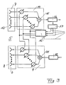
- FIG. 3 shows the schematic structure of an antenna 5 with its transmitting part 6 and receiving part 7.
- the transmitting part 6 contains a plurality of transmitting antenna elements 8, which are supplied via a beam shaping network 9 with the output signal of a transmitter 10 via a splitting circuit 11.
- the beam shaping network 9 the individual signals directed to the spatially distributed transmit antenna elements 8 are weighted differently, the setting of the weighting being carried out by a processor 12. Due to the different vectorial weighting, a transmission profile of the transmission part 6 of the antenna 5 is created.
- the receiving part 7 of the antenna 5 has a plurality of receiving antenna elements 13 which are connected to a receiver 16 via a beam shaping network 14 and a summer 15. Due to the weighting within the beam shaping network 14 controlled by the same processor 12, a spatial sensitivity distribution in the form of a reception profile is brought about.
- An evaluation circuit 17 is connected to the receiver 16 and comprises a series of Can create information 20 that can be used by processor 12 to create suitable transmit and receive profiles.
- the processor 12 can also receive information, for example, about the weight distribution of beam shaping networks 9, 14 of adjacent antennas 5.
- the number and arrangement of the transmitting antenna elements 8 is equal to the number and arrangement of the receiving antenna elements 13.
- the transmitting part 6 and receiving part 7 are arranged in close proximity, so that the beam shaping networks 9, 14 have the same weighting vectors from that Processor 12 received.
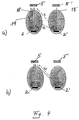
- Figure 4 shows two adjacent antennas 5, 5 'of a base station 3. These communicate with two transceivers 2, 2' in vehicles 1.
- the antennas 5, 5 'each define an illumination area 18, 18' in the form of a main lobe, the Main lobes of the transmitting parts 6 and the receiving parts 7 are identical and multiply in their effect.
- the directionality of the transceivers 2, 2 ' is low in order to ensure a desirable freedom for the attachment of the transceivers 2, 2' in the vehicles 1.
Landscapes
- Physics & Mathematics (AREA)
- General Physics & Mathematics (AREA)
- Engineering & Computer Science (AREA)
- Computer Networks & Wireless Communication (AREA)
- Business, Economics & Management (AREA)
- Finance (AREA)
- Mobile Radio Communication Systems (AREA)
- Devices For Checking Fares Or Tickets At Control Points (AREA)
Applications Claiming Priority (2)
| Application Number | Priority Date | Filing Date | Title |
|---|---|---|---|
| DE4318109A DE4318109A1 (de) | 1993-06-01 | 1993-06-01 | Verfahren und Vorrichtung zur Durchführung eines drahtlosen Datenaustausches zwischen einer Feststation und sich bewegenden Objekten |
| DE4318109 | 1993-06-01 |
Publications (2)
| Publication Number | Publication Date |
|---|---|
| EP0627717A1 true EP0627717A1 (fr) | 1994-12-07 |
| EP0627717B1 EP0627717B1 (fr) | 1998-08-12 |
Family
ID=6489323
Family Applications (1)
| Application Number | Title | Priority Date | Filing Date |
|---|---|---|---|
| EP94107433A Expired - Lifetime EP0627717B1 (fr) | 1993-06-01 | 1994-05-13 | Méthode et dispositif pour échanger des données sans fil entre un poste fixe et des objets mobiles |
Country Status (4)
| Country | Link |
|---|---|
| US (1) | US5757285A (fr) |
| EP (1) | EP0627717B1 (fr) |
| JP (1) | JP3426028B2 (fr) |
| DE (2) | DE4318109A1 (fr) |
Cited By (2)
| Publication number | Priority date | Publication date | Assignee | Title |
|---|---|---|---|---|
| AT408386B (de) * | 1994-12-23 | 2001-11-26 | Kapsch Ag | Verfahren zur erfassung von in einem begrenzten gebiet sich bewegenden objekten |
| CN103985256A (zh) * | 2014-04-28 | 2014-08-13 | 深圳威易森科技有限公司 | 车辆识别数据处理方法、装置和系统 |
Families Citing this family (20)
| Publication number | Priority date | Publication date | Assignee | Title |
|---|---|---|---|---|
| DE4446649A1 (de) * | 1994-12-19 | 1996-06-20 | Teledrive Telematik Im Verkehr | Anordnung zur automatischen Erhebung von Gebühren für die Benutzung eines Verkehrsraumes |
| US5955970A (en) * | 1997-05-19 | 1999-09-21 | Denso Corporation | On-board electronic device for use in electronic toll collection system |
| DE19741033A1 (de) * | 1997-09-18 | 1999-03-25 | Bosch Gmbh Robert | Übermitteln von Verkehrsinformationen für den Fahrer eines Fahrzeuges |
| JP3102394B2 (ja) * | 1997-11-07 | 2000-10-23 | 日本電気株式会社 | 路車間通信方式 |
| JP3857402B2 (ja) * | 1997-12-05 | 2006-12-13 | 富士通株式会社 | 交差点衝突防止方法及びシステム及び交差点衝突防止プログラムを格納した記憶媒体及び交差点装置 |
| US20040215387A1 (en) | 2002-02-14 | 2004-10-28 | Matsushita Electric Industrial Co., Ltd. | Method for transmitting location information on a digital map, apparatus for implementing the method, and traffic information provision/reception system |
| JP3481168B2 (ja) | 1999-08-27 | 2003-12-22 | 松下電器産業株式会社 | デジタル地図の位置情報伝達方法 |
| KR20010092381A (ko) * | 2000-03-21 | 2001-10-24 | 니시무로 타이죠 | 요금 징수 시스템, 온-보드 유닛 및 요금 징수 방법 |
| JP5041638B2 (ja) | 2000-12-08 | 2012-10-03 | パナソニック株式会社 | デジタル地図の位置情報伝達方法とそれに使用する装置 |
| JP4663136B2 (ja) | 2001-01-29 | 2011-03-30 | パナソニック株式会社 | デジタル地図の位置情報伝達方法と装置 |
| JP4749594B2 (ja) * | 2001-04-27 | 2011-08-17 | パナソニック株式会社 | デジタル地図の位置情報伝達方法 |
| JP4230132B2 (ja) | 2001-05-01 | 2009-02-25 | パナソニック株式会社 | デジタル地図の形状ベクトルの符号化方法と位置情報伝達方法とそれを実施する装置 |
| US20050156806A1 (en) * | 2002-02-22 | 2005-07-21 | Tomozo Ohta | Radio communication system |
| KR100402233B1 (en) * | 2002-06-11 | 2003-10-17 | Digitalsis Co Ltd | Apparatus and method for arbitrating communication between transponders having controller and plural mobile objects |
| US20040174272A1 (en) * | 2003-03-04 | 2004-09-09 | Lin Chin E. | Electronic tolling system |
| US8503328B2 (en) * | 2004-09-01 | 2013-08-06 | Qualcomm Incorporated | Methods and apparatus for transmission of configuration information in a wireless communication network |
| US7610025B2 (en) * | 2005-03-29 | 2009-10-27 | Qualcomm Incorporated | Antenna array pattern distortion mitigation |
| TW200705279A (en) * | 2005-07-29 | 2007-02-01 | Yuen Foong Yu Paper Mfg Co Ltd | Radio frequency identification (RFID) tag system and arrangement thereof |
| EP1788722A1 (fr) * | 2005-11-21 | 2007-05-23 | Nortel Networks Limited | Procédé de transmission et station de base correspondante |
| US20070126585A1 (en) * | 2005-12-06 | 2007-06-07 | Symbol Technologies, Inc. | System integration of RFID and MIMO technologies |
Citations (8)
| Publication number | Priority date | Publication date | Assignee | Title |
|---|---|---|---|---|
| EP0002469A1 (fr) * | 1977-12-05 | 1979-06-27 | Siemens Aktiengesellschaft | Dispositif pour identifier des véhicules |
| EP0401192A1 (fr) * | 1989-06-02 | 1990-12-05 | de Baets, Thierry | Système de taxation ou péage automatique pour véhicules routiers |
| EP0407243A1 (fr) * | 1989-07-04 | 1991-01-09 | Thomson-Csf | Système d'antenne à faisceaux multiples à modules actifs, et formation de faisceaux par le calcul numérique |
| EP0416692A2 (fr) * | 1989-09-04 | 1991-03-13 | Philips Electronics Uk Limited | Communication d'informations par radio |
| EP0567889A2 (fr) * | 1992-04-28 | 1993-11-03 | Robert Bosch Gmbh | Système de transmission bidirectionnelle de données entre plusieurs stations fixés et une station mobile |
| EP0578060A2 (fr) * | 1992-07-04 | 1994-01-12 | Robert Bosch Gmbh | Procédé pour la transmission de données entre une station de base et les objets mobiles |
| EP0585718A1 (fr) * | 1992-09-03 | 1994-03-09 | MARCONI S.p.A. | Système et méthode de détection automatique de véhicules roulants |
| EP0588045A1 (fr) * | 1992-08-28 | 1994-03-23 | Robert Bosch Gmbh | Procédé pour échanger des données entre une station fixe et des objets en mouvement |
Family Cites Families (10)
| Publication number | Priority date | Publication date | Assignee | Title |
|---|---|---|---|---|
| US4070675A (en) * | 1976-10-21 | 1978-01-24 | Motorola Inc. | Power rejection apparatus using a null-constrained subarray for MTI radar applications |
| US4316192A (en) * | 1979-11-01 | 1982-02-16 | The Bendix Corporation | Beam forming network for butler matrix fed circular array |
| US4298872A (en) * | 1980-05-27 | 1981-11-03 | Hughes Aircraft Company | Sidelobe blanking system |
| US5510796A (en) * | 1984-12-31 | 1996-04-23 | Martin Marietta Corporation | Apparatus for wind shear compensation in an MTI radar system |
| GB8828306D0 (en) * | 1988-12-05 | 1992-11-18 | Secr Defence | Adaptive antenna |
| US5406275A (en) * | 1990-05-17 | 1995-04-11 | At/Comm Incorporated | Object location process and apparatus |
| US5144553A (en) * | 1990-05-17 | 1992-09-01 | Hassett John J | Electronic vehicle toll collection system and method |
| JPH05304494A (ja) * | 1990-07-31 | 1993-11-16 | Internatl Telecommun Satellite Org | 無線通信システム及びその方法 |
| DE4107803A1 (de) * | 1991-03-11 | 1992-09-17 | Ant Nachrichtentech | Anordnung zum lokalisieren von objekten und zum austauschen von daten mit diesen objekten |
| US5424727A (en) * | 1994-03-22 | 1995-06-13 | Best Network Systems, Inc. | Method and system for two-way packet radio-based electronic toll collection |
-
1993
- 1993-06-01 DE DE4318109A patent/DE4318109A1/de not_active Withdrawn
-
1994
- 1994-05-13 DE DE59406642T patent/DE59406642D1/de not_active Expired - Lifetime
- 1994-05-13 EP EP94107433A patent/EP0627717B1/fr not_active Expired - Lifetime
- 1994-05-30 JP JP11663694A patent/JP3426028B2/ja not_active Expired - Fee Related
-
1996
- 1996-12-11 US US08/764,673 patent/US5757285A/en not_active Expired - Lifetime
Patent Citations (8)
| Publication number | Priority date | Publication date | Assignee | Title |
|---|---|---|---|---|
| EP0002469A1 (fr) * | 1977-12-05 | 1979-06-27 | Siemens Aktiengesellschaft | Dispositif pour identifier des véhicules |
| EP0401192A1 (fr) * | 1989-06-02 | 1990-12-05 | de Baets, Thierry | Système de taxation ou péage automatique pour véhicules routiers |
| EP0407243A1 (fr) * | 1989-07-04 | 1991-01-09 | Thomson-Csf | Système d'antenne à faisceaux multiples à modules actifs, et formation de faisceaux par le calcul numérique |
| EP0416692A2 (fr) * | 1989-09-04 | 1991-03-13 | Philips Electronics Uk Limited | Communication d'informations par radio |
| EP0567889A2 (fr) * | 1992-04-28 | 1993-11-03 | Robert Bosch Gmbh | Système de transmission bidirectionnelle de données entre plusieurs stations fixés et une station mobile |
| EP0578060A2 (fr) * | 1992-07-04 | 1994-01-12 | Robert Bosch Gmbh | Procédé pour la transmission de données entre une station de base et les objets mobiles |
| EP0588045A1 (fr) * | 1992-08-28 | 1994-03-23 | Robert Bosch Gmbh | Procédé pour échanger des données entre une station fixe et des objets en mouvement |
| EP0585718A1 (fr) * | 1992-09-03 | 1994-03-09 | MARCONI S.p.A. | Système et méthode de détection automatique de véhicules roulants |
Non-Patent Citations (1)
| Title |
|---|
| KOMANECKY ET AL.: "IVHS APPLICATIONS OF SMART CARDS", VNIS '91; VEHICLE NAVIGATION & INFORMATION SYSTEMS CONFERENCE PROCEEDINGS 1991, IEEE, 1 October 1991 (1991-10-01), US, pages 977 - 987, XP000357202 * |
Cited By (3)
| Publication number | Priority date | Publication date | Assignee | Title |
|---|---|---|---|---|
| AT408386B (de) * | 1994-12-23 | 2001-11-26 | Kapsch Ag | Verfahren zur erfassung von in einem begrenzten gebiet sich bewegenden objekten |
| CN103985256A (zh) * | 2014-04-28 | 2014-08-13 | 深圳威易森科技有限公司 | 车辆识别数据处理方法、装置和系统 |
| CN103985256B (zh) * | 2014-04-28 | 2016-07-13 | 深圳威易森科技有限公司 | 车辆识别数据处理方法、装置和系统 |
Also Published As
| Publication number | Publication date |
|---|---|
| DE4318109A1 (de) | 1994-12-08 |
| US5757285A (en) | 1998-05-26 |
| DE59406642D1 (de) | 1998-09-17 |
| EP0627717B1 (fr) | 1998-08-12 |
| JPH0722997A (ja) | 1995-01-24 |
| JP3426028B2 (ja) | 2003-07-14 |
Similar Documents
| Publication | Publication Date | Title |
|---|---|---|
| EP0627717B1 (fr) | Méthode et dispositif pour échanger des données sans fil entre un poste fixe et des objets mobiles | |
| EP0627718B1 (fr) | Méthode pour échanger des données sans fil entre un poste fixe et des objets mobiles, en particulier des véhicules | |
| DE4314739C2 (de) | Verfahren zum adaptiven Strahlbündeln eines Hochfrequnzfunksenders | |
| DE60212468T2 (de) | Verfahren und Vorrichtung zum Justieren einer Einbauanordnung für Radar, sowie Radar justiert von diesem Verfahren oder dieser Vorrichtung | |
| EP0459236B1 (fr) | Procédé pour former des communications radio en visibilité directe de postes émetteur-récepteur mobiles avec d'autres postes correspondants mobiles ou fixes | |
| WO1992015978A1 (fr) | Installation pour la localisation d'objets et l'echange de donnees avec ces objets | |
| DE20311842U1 (de) | Gerät zur Lokalisierung mobiler Endgeräte auf Grundlage von Winkelmessungen | |
| DE10022357A1 (de) | Kolonnenfahr-Steuervorrichtung | |
| DE69715127T2 (de) | Zellulares Funkübertragungssystem für Informationen zwischen einer Infrastruktur und mobilen Stationen | |
| DE2936168C2 (fr) | ||
| DE1292205B (de) | Drahtloses Nachrichten-UEbermittlungssystem zur Nachrichtenuebertragung zwischen einem sich entlang einer Spur bewegenden Fahrzeug und einer feststehenden Station | |
| DE3441269C2 (de) | Verfahren zur Lokalisierung von Störern durch Veränderung der Sekundärkeulen des Strahlungsdiagrammes | |
| EP0578060B1 (fr) | Procédé pour la transmission de données entre une station de base et les objets mobiles | |
| EP0588045B1 (fr) | Procédé pour échanger des données entre une station fixe et des objets en mouvement | |
| EP2167364A1 (fr) | Dispositif de communication et son procédé de fonctionnement | |
| DE4027186A1 (de) | Uebertragungssystem fuer schienenfahrzeuge | |
| DE2908261C2 (de) | Radargerät für ein Abstandswarnsystem für Fahrzeuge | |
| DE2009958C3 (de) | Bodenstation für ein Sekundärradarsystem mit Antwortsperrung bei Seitenkeulenabfrage und bei Umwegabfrage | |
| CH676903A5 (en) | Information transmission system for train - uses coded microwave signals fed between successive train sections | |
| WO1991007028A1 (fr) | Dispositif pour la transmission d'informations entre plusieurs stations d'abonnes d'un reseau de communication local | |
| EP1374614A2 (fr) | Procede pour controler un systeme de radiotelephonie mobile | |
| DE2708464A1 (de) | Funkempfaenger | |
| DE1957303C3 (de) | Sekundärradar-Abfrage-Antwort-System mit Zusatzantenne zur Nebenkeulenabfrageunterdrückung | |
| EP0743698A1 (fr) | Dispositif de transmission pour systèmes de communications routières | |
| EP0492051A1 (fr) | Réseau de radiotéléphone avec communication possible en dehors de la zone de couverture |
Legal Events
| Date | Code | Title | Description |
|---|---|---|---|
| PUAI | Public reference made under article 153(3) epc to a published international application that has entered the european phase |
Free format text: ORIGINAL CODE: 0009012 |
|
| AK | Designated contracting states |
Kind code of ref document: A1 Designated state(s): CH DE FR IT LI |
|
| 17P | Request for examination filed |
Effective date: 19950607 |
|
| GRAG | Despatch of communication of intention to grant |
Free format text: ORIGINAL CODE: EPIDOS AGRA |
|
| 17Q | First examination report despatched |
Effective date: 19971110 |
|
| GRAG | Despatch of communication of intention to grant |
Free format text: ORIGINAL CODE: EPIDOS AGRA |
|
| GRAH | Despatch of communication of intention to grant a patent |
Free format text: ORIGINAL CODE: EPIDOS IGRA |
|
| GRAH | Despatch of communication of intention to grant a patent |
Free format text: ORIGINAL CODE: EPIDOS IGRA |
|
| GRAA | (expected) grant |
Free format text: ORIGINAL CODE: 0009210 |
|
| AK | Designated contracting states |
Kind code of ref document: B1 Designated state(s): CH DE FR IT LI |
|
| REG | Reference to a national code |
Ref country code: CH Ref legal event code: NV Representative=s name: SCINTILLA AG, DIREKTION Ref country code: CH Ref legal event code: EP |
|
| REF | Corresponds to: |
Ref document number: 59406642 Country of ref document: DE Date of ref document: 19980917 |
|
| ET | Fr: translation filed | ||
| PLBE | No opposition filed within time limit |
Free format text: ORIGINAL CODE: 0009261 |
|
| STAA | Information on the status of an ep patent application or granted ep patent |
Free format text: STATUS: NO OPPOSITION FILED WITHIN TIME LIMIT |
|
| 26N | No opposition filed | ||
| PGFP | Annual fee paid to national office [announced via postgrant information from national office to epo] |
Ref country code: CH Payment date: 20020523 Year of fee payment: 9 |
|
| PGFP | Annual fee paid to national office [announced via postgrant information from national office to epo] |
Ref country code: FR Payment date: 20020524 Year of fee payment: 9 |
|
| PG25 | Lapsed in a contracting state [announced via postgrant information from national office to epo] |
Ref country code: LI Free format text: LAPSE BECAUSE OF NON-PAYMENT OF DUE FEES Effective date: 20030531 Ref country code: CH Free format text: LAPSE BECAUSE OF NON-PAYMENT OF DUE FEES Effective date: 20030531 |
|
| REG | Reference to a national code |
Ref country code: CH Ref legal event code: PL |
|
| PG25 | Lapsed in a contracting state [announced via postgrant information from national office to epo] |
Ref country code: FR Free format text: LAPSE BECAUSE OF NON-PAYMENT OF DUE FEES Effective date: 20040130 |
|
| REG | Reference to a national code |
Ref country code: FR Ref legal event code: ST |
|
| PG25 | Lapsed in a contracting state [announced via postgrant information from national office to epo] |
Ref country code: IT Free format text: LAPSE BECAUSE OF NON-PAYMENT OF DUE FEES;WARNING: LAPSES OF ITALIAN PATENTS WITH EFFECTIVE DATE BEFORE 2007 MAY HAVE OCCURRED AT ANY TIME BEFORE 2007. THE CORRECT EFFECTIVE DATE MAY BE DIFFERENT FROM THE ONE RECORDED. Effective date: 20050513 |
|
| PGFP | Annual fee paid to national office [announced via postgrant information from national office to epo] |
Ref country code: DE Payment date: 20120723 Year of fee payment: 19 |
|
| PG25 | Lapsed in a contracting state [announced via postgrant information from national office to epo] |
Ref country code: DE Free format text: LAPSE BECAUSE OF NON-PAYMENT OF DUE FEES Effective date: 20131203 |
|
| REG | Reference to a national code |
Ref country code: DE Ref legal event code: R119 Ref document number: 59406642 Country of ref document: DE Effective date: 20131203 |