EP0627749B1 - Mehrfarben-Drahtmarkierer - Google Patents
Mehrfarben-Drahtmarkierer Download PDFInfo
- Publication number
- EP0627749B1 EP0627749B1 EP94303421A EP94303421A EP0627749B1 EP 0627749 B1 EP0627749 B1 EP 0627749B1 EP 94303421 A EP94303421 A EP 94303421A EP 94303421 A EP94303421 A EP 94303421A EP 0627749 B1 EP0627749 B1 EP 0627749B1
- Authority
- EP
- European Patent Office
- Prior art keywords
- wire
- marker
- tape
- carrier
- coloured
- Prior art date
- Legal status (The legal status is an assumption and is not a legal conclusion. Google has not performed a legal analysis and makes no representation as to the accuracy of the status listed.)
- Expired - Lifetime
Links
- 239000003550 marker Substances 0.000 title claims description 23
- 238000000034 method Methods 0.000 claims description 12
- 239000011888 foil Substances 0.000 claims description 9
- 239000002699 waste material Substances 0.000 claims description 9
- 230000003068 static effect Effects 0.000 claims description 8
- 239000003086 colorant Substances 0.000 claims description 5
- 238000000151 deposition Methods 0.000 claims description 4
- 238000002788 crimping Methods 0.000 description 7
- 238000009413 insulation Methods 0.000 description 5
- 238000006073 displacement reaction Methods 0.000 description 4
- 238000005520 cutting process Methods 0.000 description 2
- 238000010586 diagram Methods 0.000 description 2
- 238000002360 preparation method Methods 0.000 description 2
- 238000004040 coloring Methods 0.000 description 1
- 239000004020 conductor Substances 0.000 description 1
- 238000004519 manufacturing process Methods 0.000 description 1
- 238000009877 rendering Methods 0.000 description 1
- 230000000284 resting effect Effects 0.000 description 1
Images

Classifications
-
- H—ELECTRICITY
- H01—ELECTRIC ELEMENTS
- H01B—CABLES; CONDUCTORS; INSULATORS; SELECTION OF MATERIALS FOR THEIR CONDUCTIVE, INSULATING OR DIELECTRIC PROPERTIES
- H01B13/00—Apparatus or processes specially adapted for manufacturing conductors or cables
-
- Y—GENERAL TAGGING OF NEW TECHNOLOGICAL DEVELOPMENTS; GENERAL TAGGING OF CROSS-SECTIONAL TECHNOLOGIES SPANNING OVER SEVERAL SECTIONS OF THE IPC; TECHNICAL SUBJECTS COVERED BY FORMER USPC CROSS-REFERENCE ART COLLECTIONS [XRACs] AND DIGESTS
- Y10—TECHNICAL SUBJECTS COVERED BY FORMER USPC
- Y10S—TECHNICAL SUBJECTS COVERED BY FORMER USPC CROSS-REFERENCE ART COLLECTIONS [XRACs] AND DIGESTS
- Y10S118/00—Coating apparatus
- Y10S118/21—Wire and cord striper
Definitions
- This invention relates to a multi-colour wire marker, and in particular, for marking mono-coloured insulated wire with hot foil coloured tape.
- Cable harness leads are often prepared by an automated process whereby a cable making machine, for example, feeds electrical conducting wires from a barrel, cutting the various wires into their required lengths and terminating the ends by crimping to a connector or leaving the ends free.
- Some automated cable makers feed simultaneously from a multitude of barrels that have different coloured electrical conducting wires, and there is therefore no need to mark the wire during preparation of the lead.
- a more cost effective way, however, of producing leads is to use a cable making machine that feeds off only one barrel of mono coloured electrical conducting wire. This means however, that if distinguishable marking is required on the various wires of a lead, then some sort of marking process must be coupled to the lead maker.
- FR-A-2 513 002 discloses a multiple colour wire marker comprising a base and a plurality of cassettes with a pair of spools on which are wound coloured tapes.
- the cassettes are manually mountable and removable with respect to a wire driving support of the base so that different coloured marks may be deposited on the wire.
- the cassettes can be placed at different positions parallel to the wire, whereby the position of the marks deposited on the wire correspond to the position of the tapes.
- an object of this invention is to produce a multi-colour wire marker that can be easily interfaced with a standard lead making device and that can simultaneously colour mark the wire during the lead making process.
- the invention consists in a method of marking a wire with multiple colours, comprising the step of holding the wire in a static position with respect to a base of a multiple colour wire marker having a carrier of a plurality of depositable coloured products for depositing on the wire; and being characterised by:- indexably moving the carrier with respect to the base in a direction parallel to the held wire, such that any of said coloured products on the carrier is capable of being deposited in a predetermined position on a portion of said held wire.
- the invention consists in a multiple colour wire marker comprising a base relative to which a wire to be marked is intended to be held in a static position, and a carrier for supporting a plurality of coloured products for depositing on the wire, characterised in that the carrier is indexably movable with respect to the base in a direction parallel to the wire to be marked when said wire is held in said static position, such that any of said coloured products is capable of being deposited in a predetermined position on a portion of said held wire.
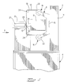
- a multi-colour wire marker is shown generally at 2, comprising a base 4, a carriage housing 6, a ram housing 8, and an anvil 10.
- a wire 12 to be colour marked is shown lying against the anvil 10.
- the base 4 has a slideway 14 onto which the carriage 6 is slidably mounted by way of a slide 15, the movement and positioning of the carriage housing 6 is driven respectively by a motor and index mechanism (not shown), such that the carriage housing can move towards and away from the plane of the paper, as viewed in Figure 1.
- the carriage housing 6 has a plurality of rollers 16, onto each of which is rolled a long strip of different coloured hot foil tape 18.
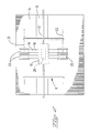
- the plurality of rollers 16 comprises two rows of rollers between which the tape 18 is held spanning the wire 12 and anvil 10, an upper row of feed rollers 20 and a lower row of waste rollers 22.
- each feed roller 20 there is a corresponding waste roller 22, the plurality of feed rollers and their corresponding waste rollers aligned respectively along axes 21 and 23 as shown in Figure 2.
- the individual pairs of feed rollers 20 and corresponding waste rollers 22 are individually indexably rotatable such that the tape 18 corresponding to one pair of rollers 20,22 can be fed independently of the other tapes (the drive mechanism of the rollers is not shown).
- the tape 18 has on its front side a coloured product 19 that can be deposited on the wire 12 to be marked.
- Unused tape 18 is fed from the feed roller 20 to the corresponding waste roller 22 that gathers the tape 18 that has already been used for marking the wire 12, whereby only the tape 18, that has been used for marking, is indexably fed by its corresponding rollers 20,22.
- Pairs of tensioning bars 24 make sure the tape 18, spanning the wire 12 and anvil 10 between the feed roller 20 and the waste roller 22, is kept under constant tension, which is especially important for feeding, guiding and marking without danger of breaking the tape 18.
- the tension bars 24 are resiliently biased against the back side of the tape 18 and this resilience force can be adjusted thereby enabling optimal tensioning of the tape 18.
- the ram housing 8 which is supported in a static relation to the base 4, has a ram 26 that is adjustably heated to a predetermined temperature, the ram 26 movable against the back side of the tape 18 such that the tape 18 is pressed against the wire 12.
- the anvil 10 has a piston 27 having a front surface 28 that opposes a front surface 30 of the ram 26, the wire 12 resting against the surface 28 of the anvil 10.
- the anvil 10 is fixed to the base 4 and serves to counteract the pressure that the ram 26 applies to the wire 12 through the tape 18, this pressure being suitably controlled by the piston 27.
- the heat and pressure applied to the tape 18 against the wire 12 causes the coloured product 19 mounted on the front side of the tape to melt off and deposit onto the wire 12, thereby marking it with a colour.
- the temperature and the time under which the wire 12 and hot foil tape 18 are subject to pressure is adjustable by means within the ram housing 8 (not shown).
- the appropriate tape 18 To mark the wire 12 with a predetermined colour, the appropriate tape 18 must first be moved to a position where it is in between the anvil front surface 28 and the ram front surface 30.
- anyone of the different coloured tapes 18 which are mounted on the rollers 20, 22 one next to the other, is movable to the marking position between the front face 28 of the anvil and the front face 30 of the ram by translation of the carriage housing 6 along the slide 15, whereby an index mechanism ensures that the chosen coloured tape 18 is precisely positioned between the face 28 and 30 for marking.
- the wire 12 is held straight along the portion to be marked, and the tape carriage housing 6 moves along the slide 15 parallel thereto.
- the wire 12 can be marked with one colour by single stamping as shown in Figure 4 or by two colours from directly neighbouring tapes in double stamping as shown in Figure 3.
- the corresponding tape 18 is indexed to a central position along the width of the ram front face 30, but for double stamping the corresponding two neighbouring tapes 18 are moved to a central position along the width of the ram front face 30.
- the width of the ram 26 is such that it extends over not only the gap separating two neighbouring tapes 18, but also a portion of both tapes 18, thus making double stamping possible.
- FIG. 6 a schematic block diagram of a lead making machine is shown with a marking station 100, a wire striping and crimping station 102 and an insulation displacement contacting (IDC) station 104.
- the wire for making the lead enters at an end 106 proximate the wire marking station 100 and the completed harness exits at another end 108 proximate the insulation displacement contacting section 104.
- a hybrid harness is generally shown at 110 comprising an insulation displacement connector 112, conducting wires 114 and crimped electrical terminals 116 at another end of the wires 114 than the connector 112.
- the harness making machine 100, 102, 104 is set up for producing a hybrid connector such as the connector 110 whereby a plurality of leads 114 are connected to a connector 112 having insulation displacement (IDC) terminals therein and at the other end crimped to various terminals 116, the individual leads 114 of various lengths.
- IDC insulation displacement
- One of the prior art solutions for marking the leads 114 is to have a mono-coloured marker station 100 that marks the leads alphanumerically. It has been found, however, that it is difficult to distinguish between the leads without alphanumerical marking thus rendering connection of the terminals 116 tiresome and prone to error. Colour markings are a lot easier and quicker to distinguish and it is therefore advantageous to provide colour marking of the wires as opposed to alphanumerical marking.
- the marking station 100 of the preferred embodiment of this invention therefore comprises the colour marker 2 as described above.
- the multi-colour wire marker 2 is positioned from the stripping and crimping station 102 at a distance L which is substantially equivalent to the sum of the lead lengths 114 of the harness 110 to be produced by the machine.
- the producing of the hybrid harness 110 will now be described.
- a single mono-coloured wire is fed from the entry end 106 past the multi colour wire marker 2, through to the stripping and crimping station 102.
- the hybrid harness to be produced comprises three leads 114 of lengths l 1 , l 2 and l 3 respectively.
- the wire is stripped of a part of its insulation and crimped to a terminal 116, and simultaneously the wire is colour marked at the station 100.
- the wire is then advanced by a length l 1 , corresponding to the length of the first lead, and then cut whereby the lead l 1 is transported to the IDC station 104 and the other end terminated to an IDC terminal of the connector 112; and simultaneously the new end of the wire is stripped and crimped to a terminal 116 at the station 102 and the wire is colour marked at the station 100.
- the wire is then advanced by a length l 2 whereby the same process as described above recommences followed by the next step which advances the cable by the length l 3 .
- the harness 110 is thus completed and ejected from the machine at the end 108.
- the whole cycle recommences with the machine successively moving the wire by the lengths by the lengths l 1 , l 2 and l 3 .
- the colour mark 118 is always situated proximate the crimped terminal end 116 of the harness 110.
- a harness 110 can be produced with leads 114 of mono-coloured wire having rapid and easily identifiable colour markings at free ends 116 thereof.
- the colour marking machine 2 can also be easily interfaced with a standard lead making machine 102, 104 without increasing the lead production cycle time as the colour marking occurs during the stripping and crimping stop time of the wire.
- multi-colour wire marker 2 as described herein is only representative of the preferred embodiment of the invention.
Landscapes
- Engineering & Computer Science (AREA)
- Manufacturing & Machinery (AREA)
- Insulated Conductors (AREA)
- Manufacturing Of Electric Cables (AREA)
Claims (11)
- Verfahren zum Markieren einer Ader (12) mit mehreren Farben, mit dem Schritt des Haltens der Ader (12) in einer statischen Position bezüglich einer Basis (4) eines Mehrfarben-Adermarkierers (2) mit einem Träger (6) mehrerer auftragbarer farbiger Produkte (19) zum Auftrag auf der Ader (12);
und gekennzeichnet durch:
weiterschaltbares Bewegen des Trägers (6) bezüglich der Basis (4) in einer Richtung parallel zu der gehaltenen Ader (12), so daß ein beliebiges der farbigen Produkte (19) auf dem Träger (6) an einer vorbestimmten Stelle auf einem Teil der gehaltenen Ader (12) aufgetragen werden kann. - Verfahren nach Anspruch 1, bei dem die farbigen Produkte (19) auf dem Träger (6) Seite an Seite entlang einer Achse (21) parallel zu dieser aufgetragen werden können.
- Verfahren nach Anspruch 1 oder 2, bei dem durch ein Heißfilmband (18) des Markierers (2), auf dem eines der farbigen Produkte (19) angebracht ist, Druck und Wärme auf die Ader (12) einwirken, um zu bewirken, daß sich das farbige Produkt (19) von dem Band (18) löst und mit der Ader (12) verbindet.
- Verfahren nach Anspruch 3, bei dem jedes der Heißfilmbänder (18) von jeweiligen Zuführrollen (20) abgespult wird, die individuell weitergeschaltet werden können, so daß nur das eine oder die mehreren Bänder (18), die zum Markieren der Ader (12) verwendet worden sind, von einer jeweiligen Abfallrolle (22) individuell weiterschaltbar gesammelt werden.
- Verfahren nach Anspruch 3 oder 4, bei dem ein etwa konstanter Zug an das Band (18) während des Markierens der Ader (12) damit angelegt wird.
- Mehrfarben-Adermarkierer mit einer Basis (4), bezüglich derer eine zu markierende Ader (12) in einer statischen Position gehalten werden soll, und einem Träger (6) zum Stützen mehrerer farbiger Produkte (19) zum Auftragen auf der Ader (12), dadurch gekennzeichnet, daß der Träger (6) bezüglich der Basis (4) in einer Richtung parallel zu der zu markierenden Ader (12) weiterschaltbar bewegt werden kann, wenn die Ader (12) in der statischen Position gehalten wird, so daß ein beliebiges der farbigen Produkte (19) an einer vorbestimmten Stelle auf einem Teil der gehaltenen Ader (12) aufgetragen werden kann.
- Markierer nach Anspruch 6, bei dem an der Basis (4) eine Gleitbahn (14) befestigt ist, wobei die Gleitbahn (14) ein Gleitstück (15) aufweist, an dem der Träger (6) derart montiert ist, daß der Träger (6) gleitend daran entlang bewegt werden kann.
- Markierer nach Anspruch 6 oder 7, mit einem Amboß (10), an dem die Ader (12) in der statischen Position anliegen soll, und einem erhitzbaren Stempel (26), der gegen den Amboß (10) bewegt werden kann, so daß durch ein Heißfilmband (18), auf dem eines der farbigen Produkte (19) angebracht ist, Druck und Wärme auf die Ader (12) einwirken können, um auf diese Weise zu bewirken, daß sich das farbige Produkt (19) von dem Band (18) löst und mit der Ader (12) verbindet.
- Markierer nach Anspruch 8, bei dem der Amboß (10) einen Kolben (27) aufweist, um den auf die Ader (12) gegen den Stempel (26) ausgeübten Druck zu steuern.
- Markierer nach Anspruch 8 oder 9, bei dem der Träger (6) Zuführrollen (20) und zugeordnete Abfallrollen (22) zum Stützen der Heißfilmbänder (18) aufweist, wobei die Zuführrollen (20) individuell weitergeschaltet werden können, so daß das eine oder die mehreren Bänder (18), die zum Markieren der Ader (12) verwendet worden sind, von ihrer jeweiligen Abfallrolle (22) individuell weiterschaltbar gesammelt werden können.
- Markierer nach Anspruch 8, 9 oder 10, mit einstellbaren Zugstäben (24), die so angeordnet sind, daß das Band (18) über die Ader (12) gespannt wird und beim Markieren der Ader (12) damit am Band (18) ein einstellbarer und etwa konstanter Zug aufrechterhalten wird.
Applications Claiming Priority (2)
| Application Number | Priority Date | Filing Date | Title |
|---|---|---|---|
| GB9311015 | 1993-05-28 | ||
| GB939311015A GB9311015D0 (en) | 1993-05-28 | 1993-05-28 | Multi-colour wire marker |
Publications (3)
| Publication Number | Publication Date |
|---|---|
| EP0627749A2 EP0627749A2 (de) | 1994-12-07 |
| EP0627749A3 EP0627749A3 (en) | 1996-04-24 |
| EP0627749B1 true EP0627749B1 (de) | 1999-02-10 |
Family
ID=10736261
Family Applications (1)
| Application Number | Title | Priority Date | Filing Date |
|---|---|---|---|
| EP94303421A Expired - Lifetime EP0627749B1 (de) | 1993-05-28 | 1994-05-12 | Mehrfarben-Drahtmarkierer |
Country Status (5)
| Country | Link |
|---|---|
| US (1) | US5452517A (de) |
| EP (1) | EP0627749B1 (de) |
| JP (1) | JPH06338229A (de) |
| DE (1) | DE69416455T2 (de) |
| GB (1) | GB9311015D0 (de) |
Families Citing this family (6)
| Publication number | Priority date | Publication date | Assignee | Title |
|---|---|---|---|---|
| US5643628A (en) * | 1995-06-05 | 1997-07-01 | United States Surgical Corporation | Suture tipping apparatus and method |
| US7296334B2 (en) | 2001-08-27 | 2007-11-20 | Yazaki Corporation | Method and device for manufacturing wire harness |
| EP1463066A4 (de) * | 2001-11-27 | 2006-12-27 | Yazaki Corp | Verfahren zur bestellungsquittierungserstellung eines kabelbaums und bestellungsquittierungserstellungssystem dafür |
| WO2003058647A1 (en) * | 2001-12-28 | 2003-07-17 | Yazaki Corporation | Method for order receipt production of electric wire and its order receipt production system |
| US9506176B2 (en) * | 2014-07-14 | 2016-11-29 | Crayola, Llc | Thread coloring apparatus |
| GB201412502D0 (en) | 2014-07-14 | 2014-08-27 | Fuse London Ltd | Threading apparatus |
Family Cites Families (15)
| Publication number | Priority date | Publication date | Assignee | Title |
|---|---|---|---|---|
| US2428284A (en) * | 1943-08-18 | 1947-09-30 | Western Electric Co | Strand marking apparatus |
| US4047271A (en) * | 1976-01-02 | 1977-09-13 | Interdye Technology Corporation | Method for space dyeing yarn |
| JPS53106488A (en) * | 1977-02-25 | 1978-09-16 | Showa Electric Wire & Cable Co | Method of adhering electric wire measuring mark |
| US4387665A (en) * | 1981-08-10 | 1983-06-14 | Clinton Henry H | Electronic band marking controller |
| FR2513002A1 (fr) * | 1981-09-17 | 1983-03-18 | Renault Vehicules Ind | Machine de marquage, en particulier pour des fils electriques |
| JPS58175215A (ja) * | 1982-04-07 | 1983-10-14 | 昭和電線電纜株式会社 | プラスチツクシ−スケ−ブルのマ−キング方法 |
| JPS58223212A (ja) * | 1982-06-19 | 1983-12-24 | 住友電気工業株式会社 | 絶縁体が架橋される電線、ケ−ブルの浮彫りマ−キング法 |
| US4543002A (en) * | 1983-06-16 | 1985-09-24 | Genicom Corporation | Multicolor printing |
| JPS6017807A (ja) * | 1983-07-11 | 1985-01-29 | 株式会社フジクラ | 標識入ケ−ブル及びその製造方法 |
| JPS60105115A (ja) * | 1983-11-09 | 1985-06-10 | 日立電線株式会社 | ケ−ブル表面標識印刷方法 |
| JPS60107348A (ja) * | 1983-11-16 | 1985-06-12 | Hitachi Cable Ltd | ケ−ブル表面標識印刷方法 |
| JPS60151906A (ja) * | 1984-01-19 | 1985-08-10 | トヨタ自動車株式会社 | 被覆電線への識別マ−キング方法 |
| JPH07100207B2 (ja) * | 1986-05-09 | 1995-11-01 | 大同特殊鋼株式会社 | 線材のマーキング装置 |
| FR2610447B1 (fr) * | 1987-01-29 | 1990-05-25 | Peugeot | Dispositif de marquage de fils electriques |
| DE3942483A1 (de) * | 1989-12-22 | 1991-06-27 | Kabelmetal Electro Gmbh | Verfahren zur fortlaufenden kennzeichnung von langgestrecktem gut |
-
1993
- 1993-05-28 GB GB939311015A patent/GB9311015D0/en active Pending
-
1994
- 1994-05-02 US US08/236,279 patent/US5452517A/en not_active Expired - Fee Related
- 1994-05-12 DE DE69416455T patent/DE69416455T2/de not_active Expired - Fee Related
- 1994-05-12 EP EP94303421A patent/EP0627749B1/de not_active Expired - Lifetime
- 1994-05-27 JP JP6138371A patent/JPH06338229A/ja active Pending
Also Published As
| Publication number | Publication date |
|---|---|
| EP0627749A2 (de) | 1994-12-07 |
| DE69416455D1 (de) | 1999-03-25 |
| US5452517A (en) | 1995-09-26 |
| GB9311015D0 (en) | 1993-07-14 |
| EP0627749A3 (en) | 1996-04-24 |
| JPH06338229A (ja) | 1994-12-06 |
| DE69416455T2 (de) | 1999-08-05 |
Similar Documents
| Publication | Publication Date | Title |
|---|---|---|
| US4476629A (en) | Method and apparatus for producing wire harness | |
| US4653160A (en) | Apparatus for making finished wire harnesses or sub-assemblies therefor | |
| US5878489A (en) | Method of producing flat electric wire harnesses | |
| EP0137631B1 (de) | Einrichtung zum automatischen Herstellen eines Kabels mit angequetschten Endstücken | |
| US4616396A (en) | Wire length varying device in combination with apparatus for making electrical harnesses | |
| EP0132092B1 (de) | Vorrichtung zur Herstellung eines Kabelbaumes | |
| US4290179A (en) | Cable harness assembly machine | |
| EP0844705B1 (de) | Verfahren und Vorrichtung zur Sicherstellung einer Drahtzuführungslänge bei der Herstellung von Kabelbäumen | |
| US5745975A (en) | Wire harness termination apparatus for programmable connectors | |
| WO1989005047A1 (en) | Electrical cable-making apparatus | |
| EP0101488B1 (de) | Verfahren und anordnung für das anbringen von zweiteiligen verbinderblöcken an einem vielleiterkabel | |
| US4976294A (en) | Method and apparatus for making specified-length wires for wire harness | |
| US4347651A (en) | System for manufacturing connection wires | |
| US5471741A (en) | Wire harness termination apparatus | |
| US4403407A (en) | Multiple wire terminal applying | |
| US5452517A (en) | Multi color wire marker | |
| EP0181780A2 (de) | Drahtvorbereitungssystem | |
| EP0145416B1 (de) | Apparat zur Herstellung von elektrischen Drahtbäumen | |
| US5732457A (en) | Electrical wire harness binding apparatus | |
| US4030174A (en) | Installation for preparing cable lengths for plug extrusion | |
| US6353993B1 (en) | Cable finishing and resistance testing machine | |
| EP0168141B1 (de) | Gerät und Verfahren zum Zusammenfassen von mit Kontakten versehenen Drähten zur Herstellung von Kabelbäumen | |
| GB2039806A (en) | Automatic apparatus for preparing electrical conductors | |
| US5067399A (en) | Wire marking apparatus for marking selected codes onto any of a plurality of wires | |
| GB2041256A (en) | Improvements in or relating to electric wiring harness |
Legal Events
| Date | Code | Title | Description |
|---|---|---|---|
| PUAI | Public reference made under article 153(3) epc to a published international application that has entered the european phase |
Free format text: ORIGINAL CODE: 0009012 |
|
| AK | Designated contracting states |
Kind code of ref document: A2 Designated state(s): DE FR GB |
|
| PUAL | Search report despatched |
Free format text: ORIGINAL CODE: 0009013 |
|
| AK | Designated contracting states |
Kind code of ref document: A3 Designated state(s): DE ES FR GB IT NL |
|
| 17P | Request for examination filed |
Effective date: 19960617 |
|
| 17Q | First examination report despatched |
Effective date: 19970409 |
|
| GRAG | Despatch of communication of intention to grant |
Free format text: ORIGINAL CODE: EPIDOS AGRA |
|
| GRAG | Despatch of communication of intention to grant |
Free format text: ORIGINAL CODE: EPIDOS AGRA |
|
| GRAH | Despatch of communication of intention to grant a patent |
Free format text: ORIGINAL CODE: EPIDOS IGRA |
|
| GRAH | Despatch of communication of intention to grant a patent |
Free format text: ORIGINAL CODE: EPIDOS IGRA |
|
| RBV | Designated contracting states (corrected) |
Designated state(s): DE FR GB |
|
| GRAA | (expected) grant |
Free format text: ORIGINAL CODE: 0009210 |
|
| AK | Designated contracting states |
Kind code of ref document: B1 Designated state(s): DE FR GB |
|
| REF | Corresponds to: |
Ref document number: 69416455 Country of ref document: DE Date of ref document: 19990325 |
|
| ET | Fr: translation filed | ||
| PLBE | No opposition filed within time limit |
Free format text: ORIGINAL CODE: 0009261 |
|
| STAA | Information on the status of an ep patent application or granted ep patent |
Free format text: STATUS: NO OPPOSITION FILED WITHIN TIME LIMIT |
|
| 26N | No opposition filed | ||
| PGFP | Annual fee paid to national office [announced via postgrant information from national office to epo] |
Ref country code: FR Payment date: 20010503 Year of fee payment: 8 |
|
| PGFP | Annual fee paid to national office [announced via postgrant information from national office to epo] |
Ref country code: DE Payment date: 20010530 Year of fee payment: 8 |
|
| REG | Reference to a national code |
Ref country code: GB Ref legal event code: IF02 |
|
| PG25 | Lapsed in a contracting state [announced via postgrant information from national office to epo] |
Ref country code: DE Free format text: LAPSE BECAUSE OF NON-PAYMENT OF DUE FEES Effective date: 20021203 |
|
| PG25 | Lapsed in a contracting state [announced via postgrant information from national office to epo] |
Ref country code: FR Free format text: LAPSE BECAUSE OF NON-PAYMENT OF DUE FEES Effective date: 20030131 |
|
| REG | Reference to a national code |
Ref country code: FR Ref legal event code: ST |
|
| PGFP | Annual fee paid to national office [announced via postgrant information from national office to epo] |
Ref country code: GB Payment date: 20040406 Year of fee payment: 11 |
|
| PG25 | Lapsed in a contracting state [announced via postgrant information from national office to epo] |
Ref country code: GB Free format text: LAPSE BECAUSE OF NON-PAYMENT OF DUE FEES Effective date: 20050512 |
|
| GBPC | Gb: european patent ceased through non-payment of renewal fee |
Effective date: 20050512 |