EP0628252B1 - Verfahren und Einrichtung zur Behandlung von Produkten, insbesondere Nahrungsprodukten, in einem ventilierten Zimmer - Google Patents
Verfahren und Einrichtung zur Behandlung von Produkten, insbesondere Nahrungsprodukten, in einem ventilierten Zimmer Download PDFInfo
- Publication number
- EP0628252B1 EP0628252B1 EP94201647A EP94201647A EP0628252B1 EP 0628252 B1 EP0628252 B1 EP 0628252B1 EP 94201647 A EP94201647 A EP 94201647A EP 94201647 A EP94201647 A EP 94201647A EP 0628252 B1 EP0628252 B1 EP 0628252B1
- Authority
- EP
- European Patent Office
- Prior art keywords
- fluid
- plant
- apertures
- conduits
- pair
- Prior art date
- Legal status (The legal status is an assumption and is not a legal conclusion. Google has not performed a legal analysis and makes no representation as to the accuracy of the status listed.)
- Expired - Lifetime
Links
Images






Classifications
-
- A—HUMAN NECESSITIES
- A23—FOODS OR FOODSTUFFS; TREATMENT THEREOF, NOT COVERED BY OTHER CLASSES
- A23B—PRESERVATION OF FOODS, FOODSTUFFS OR NON-ALCOHOLIC BEVERAGES; CHEMICAL RIPENING OF FRUIT OR VEGETABLES
- A23B4/00—Preservation of meat, sausages, fish or fish products
- A23B4/044—Smoking; Smoking devices
- A23B4/052—Smoke generators ; Smoking apparatus
-
- A—HUMAN NECESSITIES
- A23—FOODS OR FOODSTUFFS; TREATMENT THEREOF, NOT COVERED BY OTHER CLASSES
- A23B—PRESERVATION OF FOODS, FOODSTUFFS OR NON-ALCOHOLIC BEVERAGES; CHEMICAL RIPENING OF FRUIT OR VEGETABLES
- A23B2/00—Preservation of foods or foodstuffs, in general
- A23B2/90—Preservation of foods or foodstuffs, in general by drying or kilning; Subsequent reconstitution
-
- A—HUMAN NECESSITIES
- A23—FOODS OR FOODSTUFFS; TREATMENT THEREOF, NOT COVERED BY OTHER CLASSES
- A23B—PRESERVATION OF FOODS, FOODSTUFFS OR NON-ALCOHOLIC BEVERAGES; CHEMICAL RIPENING OF FRUIT OR VEGETABLES
- A23B4/00—Preservation of meat, sausages, fish or fish products
- A23B4/03—Drying; Subsequent reconstitution
- A23B4/031—Apparatus for drying
Definitions
- the invention concerns a plant for the treatment of products, particularly foodstuffs such as preserved meats, in a ventilated chamber, i. e. an assembly of devices designed to subject edible products in particular to processing such as cooking, drying, curing and the like.
- the prior art involves treatment plants comprising chambers or cells or areas in general in which the products, arranged on hangers suspended from guide-rails or on trolleys, are bathed in a current of air ducted at controlled pressure, flow-rate and temperature in order to obtain the required treatment.
- the hangers, or the trolleys are distributed in a plurality of longitudinal rows with, or without, a central gangway and a pair of lateral gangways adjacent to the walls on which the said conduits are mounted with diffusers directed towards the centre of the chamber so that the air converges towards the centre of the chamber and flows upwards in the central gangway towards one or more longitudinal extraction conduits located near the ceiling.
- the diffusers may be mounted on the ceiling, extraction occurring at floor level.
- the critical height of each cell is limited to 2.5-3 m, given the progressive increase in the humidity of the air towards the extraction conduits and the consequent progressive reduction in drying capacity, which leads to a less than optimum exploitation of the available space in the production plant.
- a plant having the features comprised in the preamble of claim 1, is known from EP-A-449 388.
- the invention resolves the said technical problem by adopting a treatment plant for food products in general, defined by a combinatio of features as set forth in claim 1.
- the products to be treated being supported on mobile conveyor frames, such as trolleys, or hangers suspended form rails fixed to the ceiling, distributed uniformly over the whole area of the chamber, or a part of it; the conveyors constituting one of the end rows of said formation being fitted with panels, mounted removably on the said frames, the whole constituting a transverse dividing wall in the treatment chamber.
- mobile conveyor frames such as trolleys, or hangers suspended form rails fixed to the ceiling, distributed uniformly over the whole area of the chamber, or a part of it;
- the conveyors constituting one of the end rows of said formation being fitted with panels, mounted removably on the said frames, the whole constituting a transverse dividing wall in the treatment chamber.
- the advantages offered by the invention are: greater uniformity in the treatment of the products, irrespective of the disposition, be it transverse or longitudinal, or height of said products; more rational exploitation of said space, achieved both by the absence of lateral or central gangways in the chamber and by the possibility of having taller chambers; optimum treatment of the products, even with reduced loads; greater reliability; reduction in energy costs because of the optimum exploitation of the air flows directed selectively to the area in which the product is present.
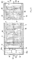
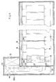
- the figures show: 1, the plant 1 for the circulation of a gaseous fluid in the chamber 2 for the treatment of products 3, for example, sausages to be dried, cured, cooked or preserved.
- the gaseous fluid may be made up of air, water vapour, mixtures of nitrogen, carbon dioxide or other gases having controlled temperature and humidity to make the atmosphere of the chamber 2 suitable for drying, humidifying, preserving or other.
- a predetermined quantity of aromas in the gaseous state for example aromatic or non-aromatic smoke, may be added to the gaseous fluid.
- the products 3 are carried on conveyor frames 4, for example, hangers suspended from guide-rails 5 mounted on the ceiling 6 ( Figure 2) of the chamber 2, trolleys resting on the floor 7, or fixed shelving, the latter not shown.
- the chamber 2 comprises a front end-wall 8, generally including an access door 8a, back end-wall 9 and a pair of side walls 10, the latter being furnished with conduits, described below, for the circulation of the fluid; the walls, and also the ceiling and floor, being insulated.
- a machine chamber 11 accessible, for example, from the rear for the maintenance or the regulation of a conditioner 12 of the processing fluid, installed in said chamber, comprising, for example, a refrigerator, heater and humidifier of the processing fluid, as well as a fan for the propulsion of the fluid;
- the delivery conduit 13 is coupled to a fluid-flow distributor 14 for the delivery of said fluid, in controlled proportions that are gradually variable in accordance with a time cycle, through the opposing fluid-feed conduits 15, and a pair of vertical manifolds 15a, at the open lower extremities of the cavities 16 of the walls 10: the regulation of the flow in the predetermined proportions is achieved by means of an oscillating butterfly valve, having a vertical axis, not shown, inserted in the distributor 14.
- the manifolds 15a are equipped with an outlet 17, substantially central with respect to the height of the chamber 2, astride a longitudinal baffle plate 18 subdividing each cavity 16 into an upper and lower part: the length of the outlet 17 facing each part of the cavity 16 is coupled to it by a gate valve 19, the degree of opening of which is controlled in a cyclical manner.
- a battery 20 of ultraviolet lamps may be inserted inside the conduits 13, or 15, for the sterilising of the processing fluid.
- the conditioner 12 may be freely aspirated, if the machine chamber 11 can be hermetically sealed, or canalized, as in Figure 2, when it uses the intake conduits 21 having intakes 22 situated near the floor 7 and the ceiling 6 opposite the outlet of the manifold 15a, and coupled to the relative cavities 16 by means of gate valves 23.
- the gate valves 19, 23 may be of the type with a single butterfly valve, or with a series of butterfly valves in line, equi- or contra-rotating, or with deflection valves, not shown; the whole working automatically.
- the figures also show: 24, a probe to measure the temperature and humidity values in the chamber 2 for the control of the processing fluid; 25, a plurality of transverse diaphragms protruding downwards from the ceiling 6 of the chamber 2 far enough to just clear the maximum load height of the trolleys, or the topmost hangers 4, for example to the level of the rails 5: said diaphragms being distributed at longitudinal intervals P substantially equivalent to the length of the trolleys, or hangers 4, so that they can be aligned with the panels 26 ( Figure 6), moveably or removably fixed to the trolleys or hangers 4 making up the back row of the batch loaded in the chamber 2, so as to form a dismantlable transverse wall and so reduce the effective volume of the chamber itself, when working at part load, thereby maintaining the optimum parameters of relative velocity of the fluid with respect to the product in all sections of the chamber 2; 27, the cutout sections in the diaphragms 25 coinciding with the rolling device 28 of the hangers on the guide-rails 5; 29, the
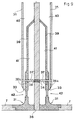
- the corners between lateral walls 10 and floor 7 or ceiling 6 featuring connecting elements 31, inserted in the cavities 16 and having an internal surface 32 converging towards the longitudinal apertures 33 for the passage through them of the processing fluid; the areas for the passage of the processing fluid being for example made up of longitudinal slits extending substantially for the entire length of the lateral walls 10: the connecting elements 31 having an ample internal rounded surface with a radius of curvature of between about 20 cm and 40 cm, to deflect the stream of fluid flowing out of the apertures 33, or being extracted towards them, with limited loss; 34, a trap for liquids on the floor 7 for the collection and discharge of liquids.
- the lateral walls 10 are finished internally with longitudinal panels 35 fixed to the baffle plate 18 and to the load-bearing wall 36 by means, for example, of spacers 35a, to define the transverse width of the cavities 16.
- each panel is partially superimposed on the body of each corner block 31 in such a way as to define the width of the aperture 33 for the passage of the fluid, being adjustable by means of the threaded ties 37 engaging internally in bushes 38 inserted in the load-bearing structure 36 and possibly counter-sprung by springs 38a.
- the cavities 16 may be longitudinally subdivided by means of intermediate baffles 39 so as to define, in each upper and lower part of said cavities, separate inlet conduits 40, located centrally and extraction conduits 41 located at floor and ceiling level: in this case, the profile of the intermediate baffles 39 continues into the body of the connecting elements 31 forming an integral part of it so as to form an inlet conduit converging towards apertures 33 with acceleration of the stream of fluid where it flows in; 42, longitudinal apertures similar to apertures 33 but placed lower than them, protected by grills to convey the air towards the extraction conduits 41.
- the panels 43 may also be continuous, it being envisaged that in this case the fluid inlet conduits 48 be mounted on the faces of panels themselves; the cavities 47 acting as extraction conduits for the fluid being defined between panels 43 and each load-bearing wall 36.
- externally-mounted conduits 49 may be provided for both fluid introduction and extraction.
- conduits 44, 48, 49 being fitted with truncated cone or truncated pyramid diffusers 50 together constituting a plurality of longitudinal apertures for the passage of the processing fluid.
- the figures also show: 51, possible sleeve bushes in the panels 39 loosely coupled to the ties 37; 52, elastic elements lying on substantially vertical planes, serving to straighten the fluid threads and direct them towards the floor or ceiling during extraction and introduction, placed between the panels 35 and the flat sections of the corner connecting elements 31 or of the intermediate panels 39 facing the longitudinal apertures 33: said elements consisting for example of flexible prismatic blades glued or fixed in some way to the panels themselves, or protruding from the surface of a belt of elastic material; alternatively, (Figure 19) the straightening elements, flexible or not, consisting of staggered projections on the opposing surfaces of the relative panels 35, 31 facing one another to induce losses of momentum in the longitudinal flow of the fluid by directing the fluid threads towards the floor or ceiling: said projections similarly being an integral part of or in some way fixed to the relative panels.
- the cavities 16 may be fitted internally with tubes 53 advantageously extending for the whole length of the cavities themselves for the spraying of detergent liquid through atomizer nozzles 54 against the internal walls of the cavities.
- the longitudinal baffle plates 18 being fixed to the wall 36 by threaded ties 37, with the insertion of soft gaskets 55: the heads of the ties being advantageously protected by covers 56 inserted in special grooves in the panel 35.
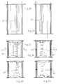
- Operation is as follows: having filled the treatment chamber 2, after the eventual formation of a modular diaphragm by aligning the corresponding panels 26 with one of the baffles 25, the conditioner 12 is switched on to send the fluid under pressure through the conduits 13, 15, 15a and from these, through the gate valves 19, 23 alternately to the pair of upper and lower cavities 16; the extraction of the fluid may come about either through the pair of cavities not used for the introduction of the fluid, as in Figure 7, or through extraction conduits designed for this purpose, such as conduits 41, 47.
- Inversion of flow being triggered by a sequence timer controlled by means of the plant's microprocessor, not shown, or by means of an electric signal sent to the microprocessor itself by one or more probes 24 measuring, for example, the degree of humidity in the chamber 2; this taking preferably periods of about 1/2 an hour to about one hour for feeding the pair of lower cavities and from about 20 to 40 minutes for feeding the pair of upper cavities.
- the flow rate to the cavity 16 of each pair being rendered variable by operating the distributor 14 so as to create a longitudinal stream 57 of fluid, substantially vertical in its central section and directed by extraction towards the input, obtained by the confluence of the two opposing flows being sent to the chamber through the input conduits, to affect a particular area of the chamber itself extending progressively from one side wall 10 to the opposite wall.
- the output of processing fluid in the chambers according to the invention having to allow from 40 to 60 recyclings/hour, with a load density of the product to be treated of approximately 25 to 70 kg/m 3 .
Landscapes
- Life Sciences & Earth Sciences (AREA)
- Engineering & Computer Science (AREA)
- Wood Science & Technology (AREA)
- Zoology (AREA)
- Chemical & Material Sciences (AREA)
- Food Science & Technology (AREA)
- Polymers & Plastics (AREA)
- Freezing, Cooling And Drying Of Foods (AREA)
- General Preparation And Processing Of Foods (AREA)
- Preparation Of Fruits And Vegetables (AREA)
- Food Preservation Except Freezing, Refrigeration, And Drying (AREA)
- Drying Of Solid Materials (AREA)
Claims (15)
- Anlage zur Behandlung von Produkten, insbesondere von Lebensmitteln, mit: einer belüfteten Kammer (2), die sich gegenüberliegende, vertikal verlaufende Wände (10) hat, zwischen denen ein Raum festgelegt ist, in den die Produkte (3), die einer Behandlung unterzogen werden sollen, eingebracht werden, um dort einer Strömung (57) eines Fluids zur Behandlung ausgesetzt zu werden einem Vorbehandlungsapparat (12) zur Vorbehandlung des Fluids; einer Mehrzahl von Leitungen (13, 15, 16, 21, 40, 41), die an dem Vorbehandlungsapparat (12) angeschlossen sind, um das vorbehandelte Fluid zur Behandlung in die Kammer (2) zu leiten und aus der Kammer (2) abzuleiten; einem Fluidströmungsverteiler (14), der die Strömungsrate des Fluids durch die Leitungen (15, 16, 40, 41) kontrolliert; zumindest einem Paar von oberen Öffnungen (33) 42, 50), die an den oberen Enden von den sich gegenüberliegenden, vertikal verlaufenden Wänden (10) angeordnet sind, und mit zumindest einem Paar von unteren Öffnungen (33, 42, 50), die an der unteren Enden von den sich gegenüberliegenden, vertikal verlaufenden Wänden (10) angeordnet sind, wobei jede dieser Öffnungen in Fluidverbindung mit den Leitungen (15, 16, 40, 41) steht, um gegeneinander gerichtete Fluidströmungen zu erzeugen, die in der Strömung zur Behandlung zusammenströmen, wobei die Strömungsrate durch den Verteiler (14) kontrollierbar ist, dadurch gekenzeichnet, daßeine Einrichtung (19, 23) an den Leitungen (16, 21, 40, 41) vorgesehen ist, die es ermöglicht, daß alternative die oberen oder die unteren Öffnungen (33, 42, 50) für entweder die Einleitung oder die Ableitung des Fluids dienen, wobei die Fluidströmung (57) im wesentlichen vertikal verläuft und eine umkehrbare Strömungsrichtung aufweist.
- Anlage nach Anspruch 1, dadurch gekennzeichnet, daß die Einrichtung zum alternativen Einsatz der Öffnungen (33, 42, 50) Absperrschieber (19, 23) umfaßt.
- Anlage nach Anspruch 2, dadurch gekennzeichnet, daß die Seitenwände (10) jeweils ein Paar von Hohlräumen (16, 47) aufweisen, die so ausgebildet sind, daß sie als Leitungen für die Ableitung und die Einleitung des Fluids dienen, wobei sich die Hohlräume vertikal erstrecken, von gegeüberliegenden Seiten einer zwischenliegenden Ablenkplatte (18), sowie eine Platte (35), die an der Ablenkplatte (18) befestigt ist, in ihrem mittleren Abschnitt gemeinsam mit der lastaufnehmenden Wand (36) die Breite der Hohlräume bestimmt, und an ihrem Endabschnitt die Weite der oberen und der unteren Öffnungen (33, 41) bestimmt.
- Anlage nach Anspruch 1, dadurch gekennzeichnet, daß jede Seitenwand (10) der Kammer zur Behandlung (2) aus einer lastaufnehmenden Wand (36) besteht, an der ein Paar von länglichen Leitungen (49) flächig und übereinanderliegend montiert ist, die sich in der Nähe der lastaufnehmenden Wand über einen wesentlichen Teil der Höhe erstrecken; wobei das Paar von Öffnungen (50) an den oberen und den unteren Endflächen jeder beitung vorliegen.
- Anlage nach Anspruch 1, dadurch gekennzeichnet, daß jede Seitenwand (10) der Kammer zur Behandlung (2) aus einer lastaufnehmenden Wand (36) besteht, an der ein Paar von mittigen, länglichen, Einlaßleitungen (44) montiert ist, die jeweils mit einem Paar von Öffnungen (50) versehen sind, um das Fluid zu den oberen und unteren Flächen zur Behandlung zuzuführen; wobei sich ein Paar von länglichen Platten (43) von dem Boden und von der Decke erstrecken bis zu dieser oberen und unteren Flächen, um die Hohlräume (47a) auszubilden, die ein Paar von Öffnungen (42) aufweisen, um das Fluid zur Behandlung abzuleiten.
- Anlage nach Anspruch 3, dadurch gekennzeichnet, daß jeder Hohlraum (16) in der Längsrichtung durch eine mittige Ablankplatte (39) abgeteilt ist, nämlich in eine mittige Leitung (40) zur Einleitung des Fluids zur Behandlung und in eine Leitung (41) zum Abführen dieses Fluids.
- Anlage nach einem oder mehreren der vorhergehenden Ansprüche, dadurch gekennzeichnet, daß die Kammer zur Behandlung (2) mit Verbindungselementen (31) ausgestattet ist, die sich zwischen den Seitenwänden (10) befinden, sowie der Boden (7) und/oder die Decke (6) mit einer konkaven Innenfläche versehen sind, die mit der Luftströmung zusammenwirkt, um den Strömungsweg im wesentlichen um 90° abzulenken.
- Anlage nach Anspruch 7, falls von Anspruch 3 abhängig, dadurch gekennzeichnet, daß der vertikale Abschnitt jedes Verbindungselementes (31) in den jeweiligen Hohlraum (16) eingesetzt ist und daß dieser den Anschlußabschnitt festlegt, der sich in Richtung nach außerhalb der Leitungen zum Ableiten oder Einleiten des Fluids verjüngt.
- Anlage nach einem oder mehreren der vorhergehenden Ansprüche, dadurch gekennzeichnet, daß die Hohlräume (16; 47; 47a) an einem der Längsenden verschlossen sind, während das andere Langsende mittels der Absperrventile (19; 23) mit den Leitungen (13; 15; 15a; 21) zum Ableiten oder Einleiten des Fluids in Verbindung stehen.
- Anlage nach einem der Ansprüche 1 bis 8, dadurch gekennzeichnet, daß die oberen und die unteren Öffnungen (33) mit Elementen (52; 55) ausgestattet sind, die die vertikal ausgerichtete Fluidströmung geradeausleiten und die mit den gegenüberliegenden Oberflächen der Ablenkplatten (39) oder der Platten (35) zusammenwirken, die die Öffnungen selbst ausbilden.
- Anlage nach Anspruch 10, dadurch gekennzeichnet, daß diese Elemente (52) aus einem elastischen, verformbaren Material bestehen, so daß sie an die verschiedenen Abmessungen der jeweiligen Öffnung (33), angepaßt werden können.
- Anlage nach Anspruch 10, dadurch gekennzeichnet, daß diese Elemente aus versetzten, sich gegenüberliegenden Vorsprüngen (52) an den gegenüberliegenden Oberflächen der Ablenkplatten (39) oder der Platten (35) bestehen, die die oberen und die unteren Öffnungen (33) ausbilden.
- Anlage nach einem oder mehreren der vorhergehenden Ansprüche, dadurch gekennzeichnet, daß die längs verlaufenden Platten (35) durch Verbinder (37) an der lastaufnehmenden Wand (36) befestigt sind, wobei die Verbinder (37) einstellbar sind, um die Weite der Öffnungen (33) zu verändern.
- Anlage nach einem oder mehreren der vorhergehenden Ansprüche, dadurch gekennzeichnet, daß in die Kammern (2) zur Behandlung der Produkte (3) bewegliche Förderrahmen (4) eingesetzt sind, die gleichmäßig verteilt sind, und zwar über zumindest einen Teil der Fläche der Kammer; wobei die Förderer (4), die eine der Außenreihen dieser gleichmäßigen Formation bilden, mit Platten (26) versehen sind, die abnehmbar an den Rahmen montiert sind, wobei diese gesamte Anordnung, zusammen mit den feststehenden Ablenkplatten (25), die von der Decke vorstehen, eine quer angeordnete Teilungswand in der Behandlungskammer ausbildet.
- Verfahren zur Behandlung von Produkter insbesondere von Lebensmitteln, in einer Anlage nach Anspruch 1, wobei das Verfahren die folgenden Schritte umfaßt:Einbringen der Produkte in die belüftete Kammer (2);Vorsehen einer Fluidströmung (57) zur Behandlung in dieser Kammer (2), wobei die Fluidstömung {57) aus dem Zusammenwirken gegeneinander gerichteter Fluidströmungen resultiert, die von dem zumindest einen Paar von oberen Öffnungen (33, 42, 50) erzeugt werden, die an den oberen Enden der vertikal angeordneten Wände (10) angeordnet sind oder die von dem zumindest einen Paar von unteren Öffnungen (33, 42, 50) erzeugt werden, die an den unteren Enden der vertikal angeordneten Wände (10) angeordnet sind, wobei die Strömungsraten der gegeneinander gerichteten Fluidströmungen durch den Verteiler (14) kontrollierbar sind, dadurch gekennzeichnet, daß zudem die folgenden Schritte vorgesehen sind:alternative Betätigung der oberen und der unteren Öffnungen (33, 42, 50) mittels der Betätigungseinrichtung (19, 23), um entweder die Einleitung oder die Ableitung des Fluids zu bewirken, wobei die Fluidströmung (57) vorgesehen wird, die im wesentlichen vertikal verläuft und eine umkehrbare Strömungsrichtung aufweist.
Applications Claiming Priority (2)
| Application Number | Priority Date | Filing Date | Title |
|---|---|---|---|
| ITMO930079 | 1993-06-11 | ||
| ITMO930079A IT1262630B (it) | 1993-06-11 | 1993-06-11 | Impianto per il trattamento di prodotti in camera ventilata, in particolare generi alimentari, quali i salumi. |
Publications (2)
| Publication Number | Publication Date |
|---|---|
| EP0628252A1 EP0628252A1 (de) | 1994-12-14 |
| EP0628252B1 true EP0628252B1 (de) | 1998-12-23 |
Family
ID=11385435
Family Applications (1)
| Application Number | Title | Priority Date | Filing Date |
|---|---|---|---|
| EP94201647A Expired - Lifetime EP0628252B1 (de) | 1993-06-11 | 1994-06-09 | Verfahren und Einrichtung zur Behandlung von Produkten, insbesondere Nahrungsprodukten, in einem ventilierten Zimmer |
Country Status (5)
| Country | Link |
|---|---|
| EP (1) | EP0628252B1 (de) |
| AT (1) | ATE174760T1 (de) |
| DE (1) | DE69415396T2 (de) |
| ES (1) | ES2126052T3 (de) |
| IT (1) | IT1262630B (de) |
Families Citing this family (2)
| Publication number | Priority date | Publication date | Assignee | Title |
|---|---|---|---|---|
| NL1029933C2 (nl) * | 2005-09-12 | 2007-03-13 | Stork Townsend Bv | Inrichting voor het met een geconditioneerde luchtstroom behandelen van langwerpige voedselproducten. |
| IT202300019584A1 (it) * | 2023-09-22 | 2025-03-22 | Frigo Impianti S R L | Cella perfezionata per l'asciugatura di prodotti alimentari. |
Family Cites Families (5)
| Publication number | Priority date | Publication date | Assignee | Title |
|---|---|---|---|---|
| FR1484923A (fr) * | 1966-06-23 | 1967-06-16 | Wilhelm Fessmann Spezialfabrik | Dispositif pour fumer et affiner la viande et la charcuterie |
| US4310020A (en) * | 1978-11-13 | 1982-01-12 | Knud Simonsen Industries Limited | Processing chamber with an air flow reverser |
| US4409743A (en) * | 1978-11-27 | 1983-10-18 | Knud Jespersen | Perforated walls and duct system |
| DE3617345A1 (de) * | 1986-05-23 | 1987-11-26 | Josef Deutsch Koch Und Raeuche | Raeucherkammer mit raeucherkabine |
| NL9000718A (nl) * | 1990-03-27 | 1991-10-16 | Navep Bv | Klimatiseringsinrichting, in het bijzonder geschikt voor het behandelen van vleeswaren. |
-
1993
- 1993-06-11 IT ITMO930079A patent/IT1262630B/it active IP Right Grant
-
1994
- 1994-06-09 DE DE69415396T patent/DE69415396T2/de not_active Expired - Fee Related
- 1994-06-09 EP EP94201647A patent/EP0628252B1/de not_active Expired - Lifetime
- 1994-06-09 AT AT94201647T patent/ATE174760T1/de not_active IP Right Cessation
- 1994-06-09 ES ES94201647T patent/ES2126052T3/es not_active Expired - Lifetime
Also Published As
| Publication number | Publication date |
|---|---|
| DE69415396D1 (de) | 1999-02-04 |
| ITMO930079A0 (it) | 1993-06-11 |
| EP0628252A1 (de) | 1994-12-14 |
| ATE174760T1 (de) | 1999-01-15 |
| ITMO930079A1 (it) | 1994-12-11 |
| ES2126052T3 (es) | 1999-03-16 |
| IT1262630B (it) | 1996-07-04 |
| DE69415396T2 (de) | 1999-05-12 |
Similar Documents
| Publication | Publication Date | Title |
|---|---|---|
| US5702245A (en) | Conveyor for processing equipment having gas flow compensation | |
| US5322007A (en) | Compact, high-capacity oven | |
| AU718872B2 (en) | Air impingement oven | |
| EP0068135B1 (de) | Backofeneinrichtung und Verfahren zum Kochen von Nahrungsmitteln | |
| US5934178A (en) | Air impingement oven | |
| US5329916A (en) | Oven | |
| US6418834B1 (en) | Apparatus for treating an item during travel of the item along a treating trough | |
| JPH0440007B2 (de) | ||
| EP0512061A1 (de) | Backofen zum langsamen garen von nahrungsmitteln. | |
| US5960703A (en) | High performance cooking oven with steam chamber | |
| EP0628252B1 (de) | Verfahren und Einrichtung zur Behandlung von Produkten, insbesondere Nahrungsprodukten, in einem ventilierten Zimmer | |
| US20020031583A1 (en) | Method for treating an item during travel of the item along a treating trough | |
| CN101686693B (zh) | 干燥箱 | |
| US5442995A (en) | Apparatus for heat processing foodstuff | |
| EP0226673A1 (de) | Vorrichtung zur kontinuierlichen Behandlung von festen Partikeln in fliessendem Zustand | |
| CN100374806C (zh) | 粮食原生态脱水干燥装置 | |
| US4750416A (en) | Air head module | |
| EP3451844B1 (de) | Verbesserte anlage zum härten und/oder trocknen von lebensmittelprodukten | |
| US9700059B2 (en) | Treatment device and method for treating food products with conditioned air | |
| US4549072A (en) | Proofing or heating cabinet | |
| US5079855A (en) | Drying chamber and air distribution means therefor | |
| CA1221266A (en) | Impingement thermal treatment apparatus with collector plate | |
| GB2419659A (en) | A continuous multistage drying tower heated with microwaves comprises plural fluidised beds | |
| EP0449388A1 (de) | Klimaanlage, insbesondere geeignet zur Behandlung von Fleischprodukten | |
| CN208836975U (zh) | 一种果脯烘烤房 |
Legal Events
| Date | Code | Title | Description |
|---|---|---|---|
| PUAI | Public reference made under article 153(3) epc to a published international application that has entered the european phase |
Free format text: ORIGINAL CODE: 0009012 |
|
| AK | Designated contracting states |
Kind code of ref document: A1 Designated state(s): AT BE CH DE ES FR IT LI |
|
| 17P | Request for examination filed |
Effective date: 19950104 |
|
| 17Q | First examination report despatched |
Effective date: 19961211 |
|
| GRAG | Despatch of communication of intention to grant |
Free format text: ORIGINAL CODE: EPIDOS AGRA |
|
| GRAG | Despatch of communication of intention to grant |
Free format text: ORIGINAL CODE: EPIDOS AGRA |
|
| GRAG | Despatch of communication of intention to grant |
Free format text: ORIGINAL CODE: EPIDOS AGRA |
|
| GRAH | Despatch of communication of intention to grant a patent |
Free format text: ORIGINAL CODE: EPIDOS IGRA |
|
| GRAH | Despatch of communication of intention to grant a patent |
Free format text: ORIGINAL CODE: EPIDOS IGRA |
|
| GRAA | (expected) grant |
Free format text: ORIGINAL CODE: 0009210 |
|
| AK | Designated contracting states |
Kind code of ref document: B1 Designated state(s): AT BE CH DE ES FR IT LI |
|
| PG25 | Lapsed in a contracting state [announced via postgrant information from national office to epo] |
Ref country code: LI Free format text: LAPSE BECAUSE OF FAILURE TO SUBMIT A TRANSLATION OF THE DESCRIPTION OR TO PAY THE FEE WITHIN THE PRESCRIBED TIME-LIMIT Effective date: 19981223 Ref country code: CH Free format text: LAPSE BECAUSE OF FAILURE TO SUBMIT A TRANSLATION OF THE DESCRIPTION OR TO PAY THE FEE WITHIN THE PRESCRIBED TIME-LIMIT Effective date: 19981223 Ref country code: AT Free format text: LAPSE BECAUSE OF FAILURE TO SUBMIT A TRANSLATION OF THE DESCRIPTION OR TO PAY THE FEE WITHIN THE PRESCRIBED TIME-LIMIT Effective date: 19981223 |
|
| REF | Corresponds to: |
Ref document number: 174760 Country of ref document: AT Date of ref document: 19990115 Kind code of ref document: T |
|
| REG | Reference to a national code |
Ref country code: CH Ref legal event code: EP |
|
| REF | Corresponds to: |
Ref document number: 69415396 Country of ref document: DE Date of ref document: 19990204 |
|
| ET | Fr: translation filed | ||
| ITF | It: translation for a ep patent filed | ||
| REG | Reference to a national code |
Ref country code: ES Ref legal event code: FG2A Ref document number: 2126052 Country of ref document: ES Kind code of ref document: T3 |
|
| RAP2 | Party data changed (patent owner data changed or rights of a patent transferred) |
Owner name: FRIGOMECCANICA S.P.A. |
|
| REG | Reference to a national code |
Ref country code: CH Ref legal event code: PL |
|
| PLBE | No opposition filed within time limit |
Free format text: ORIGINAL CODE: 0009261 |
|
| STAA | Information on the status of an ep patent application or granted ep patent |
Free format text: STATUS: NO OPPOSITION FILED WITHIN TIME LIMIT |
|
| 26N | No opposition filed | ||
| PGFP | Annual fee paid to national office [announced via postgrant information from national office to epo] |
Ref country code: ES Payment date: 20010612 Year of fee payment: 8 |
|
| PGFP | Annual fee paid to national office [announced via postgrant information from national office to epo] |
Ref country code: BE Payment date: 20010626 Year of fee payment: 8 |
|
| PGFP | Annual fee paid to national office [announced via postgrant information from national office to epo] |
Ref country code: FR Payment date: 20010628 Year of fee payment: 8 |
|
| PGFP | Annual fee paid to national office [announced via postgrant information from national office to epo] |
Ref country code: DE Payment date: 20010830 Year of fee payment: 8 |
|
| PG25 | Lapsed in a contracting state [announced via postgrant information from national office to epo] |
Ref country code: ES Free format text: LAPSE BECAUSE OF NON-PAYMENT OF DUE FEES Effective date: 20020610 |
|
| PG25 | Lapsed in a contracting state [announced via postgrant information from national office to epo] |
Ref country code: BE Free format text: LAPSE BECAUSE OF NON-PAYMENT OF DUE FEES Effective date: 20020630 |
|
| BERE | Be: lapsed |
Owner name: *FRIGOMECCANICA S.P.A. Effective date: 20020630 |
|
| PG25 | Lapsed in a contracting state [announced via postgrant information from national office to epo] |
Ref country code: DE Free format text: LAPSE BECAUSE OF NON-PAYMENT OF DUE FEES Effective date: 20030101 |
|
| PG25 | Lapsed in a contracting state [announced via postgrant information from national office to epo] |
Ref country code: FR Free format text: LAPSE BECAUSE OF NON-PAYMENT OF DUE FEES Effective date: 20030228 |
|
| REG | Reference to a national code |
Ref country code: FR Ref legal event code: ST |
|
| REG | Reference to a national code |
Ref country code: ES Ref legal event code: FD2A Effective date: 20030711 |
|
| PG25 | Lapsed in a contracting state [announced via postgrant information from national office to epo] |
Ref country code: IT Free format text: LAPSE BECAUSE OF NON-PAYMENT OF DUE FEES Effective date: 20050609 |