EP0628285A2 - Appareil ultrasonique de mesure de l'écoulement sanguin - Google Patents
Appareil ultrasonique de mesure de l'écoulement sanguin Download PDFInfo
- Publication number
- EP0628285A2 EP0628285A2 EP94301977A EP94301977A EP0628285A2 EP 0628285 A2 EP0628285 A2 EP 0628285A2 EP 94301977 A EP94301977 A EP 94301977A EP 94301977 A EP94301977 A EP 94301977A EP 0628285 A2 EP0628285 A2 EP 0628285A2
- Authority
- EP
- European Patent Office
- Prior art keywords
- switch
- data
- filter
- blood flow
- inputted
- Prior art date
- Legal status (The legal status is an assumption and is not a legal conclusion. Google has not performed a legal analysis and makes no representation as to the accuracy of the status listed.)
- Granted
Links
Images



Classifications
-
- A—HUMAN NECESSITIES
- A61—MEDICAL OR VETERINARY SCIENCE; HYGIENE
- A61B—DIAGNOSIS; SURGERY; IDENTIFICATION
- A61B8/00—Diagnosis using ultrasonic, sonic or infrasonic waves
- A61B8/06—Measuring blood flow
-
- G—PHYSICS
- G01—MEASURING; TESTING
- G01S—RADIO DIRECTION-FINDING; RADIO NAVIGATION; DETERMINING DISTANCE OR VELOCITY BY USE OF RADIO WAVES; LOCATING OR PRESENCE-DETECTING BY USE OF THE REFLECTION OR RERADIATION OF RADIO WAVES; ANALOGOUS ARRANGEMENTS USING OTHER WAVES
- G01S15/00—Systems using the reflection or reradiation of acoustic waves, e.g. sonar systems
- G01S15/88—Sonar systems specially adapted for specific applications
- G01S15/89—Sonar systems specially adapted for specific applications for mapping or imaging
- G01S15/8906—Short-range imaging systems; Acoustic microscope systems using pulse-echo techniques
- G01S15/8979—Combined Doppler and pulse-echo imaging systems
- G01S15/8981—Discriminating between fixed and moving objects or between objects moving at different speeds, e.g. wall clutter filter
Definitions
- the present invention relates to an ultrasonic Doppler blood flow meter apparatus for measuring blood flows in living beings by utilizing an ultrasonic Doppler method in the medical field for thereby generating blood flow images.
- a two-dimensional ultrasonic Doppler blood flow meter apparatus in which a blood flow distribution in a living being is determined by making use of an ultrasonic Doppler's effect and displayed in superposition on a two-dimensional monochromatic tomograph with the blood flow distribution being displayed in a color.
- This apparatus is also known as a color flow apparatus.
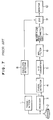
- a structure of the two-dimensional Doppler blood flow meter apparatus known heretofore is shown in Fig. 7.
- an ultrasonic transmitter 1 emits ultrasonic pulses through the medium of a probe 2 for irradiation of a portion of a living being. Echoes generated as the result of irradiation with the ultrasonic pulses are converted into an electric signal through the probe 2, which signal is then amplified by a receiver 3 and undergoes phase shift detection by a phase shift detector 4 to be thereby converted to a Doppler shift signal.
- the Doppler shift signal outputted from the phase shift detector 4 is converted into digital data through an analogue-to-digital (A/D) converter 5, the digital data being then inputted to a wall filter 6 which is generally constituted by a FIR- or IIR-type filter of degree several and which serves for eliminating unwanted signal components of low frequencies (usually referred to as the clutter) which originate in intravital tissues.
- Fig. 6 shows, by way of example, a major portion of the wall filter constituted by an IIR-type filter of second degree or order.
- the wall filter 6 of this configuration features that characteristic equivalent to that of the FIR-type filter can be realized by using a smaller number of multipliers and adders when compared with the FIR-type filter and that the cut-off characteristic can flexibly be modified by changing the feedback coefficients K1 and K2.
- the Doppler shift signal from which the clutters are eliminated by the wall filter 6 is supplied to a blood flow rate arithmetic unit 7 which is adapted to determine arithmetically the blood flow rates.
- the output of the blood flow rate arithmetic unit 7 is then inputted to a digital scan converter (hereinafter referred to as the DSC in abbreviation) 9 together with a B-mode signal outputted from an envelope detector 8.
- the DSC 9 digital scan converter
- the B-mode signal and the blood flow rate signal are mixed together, whereby a two-dimensional blood flow image is displayed on a screen of a monitor display unit 10.
- an ultrasonic Doppler blood flow meter apparatus which comprises a wall filter for eliminating clutters from an echo signal of an ultrasonic pulse signal sent to a living being under test, the wall filter having a switch for cutting a part of input data, and a control unit for controlling the switch such that the switch is opened during a period in which first m data (where m is integer) is inputted to undergo filtering by the wall filter while the switch is closed during a period in which data following the (m+1)-th data inclusive thereof are inputted.
- the switch control unit opens the switch during a period in which one or more data containing the influential transient response is being inputted for the filtering operation, to thereby prevent the data having influential transient response from being transmitted to the filter block provided downstream of the switch.
- the transient response of the wall filter can be reduced with simple hardware configuration while ensuring availability of blood flow information with high accuracy.
- Fig. 1 shows a structure of an ultrasonic Doppler blood flow meter apparatus according to a first embodiment of the invention.
- the transmitter 1, the probe 2, the receiver 3, the phase shift detector 4, the A/D converter 5, the blood flow rate arithmetic unit 7, the envelope detector 8, the DSC 9 and the monitor 10 are the same as or equivalent to those described hereinbefore in conjunction with the blood flow meter apparatus known heretofore in respect to the structure as well as operation. Accordingly, repeated description thereof will be unnecessary.
- a wall filter 20 including a switch 24 and a control unit 30 for controlling the switch.
- Fig. 2 is a block diagram showing in detail a structure of a wall filter employed in the apparatus shown in Fig. 1.
- the wall filter 20 includes a switch 24 controlled by the control unit 30.
- the control unit 30 controls the input side of the switch 24 extending from the A/D converter 5 as the preceding stage while the output side of the switch 24 leading to the blood flow rate arithmetic unit 7 is referred to as the succeeding stage.
- a filter 25 by a register 23a and an adder 21b, which filter 25 has a characteristic of (1 - Z ⁇ 1) representing Z-transformation.
- This filter 25 is an FIR-type filter of first degree (or order) and exhibits such characteristic that only the first data of an input data train or sequence contains transient response with the following data inclusive of the second having no transient response.
- the output of the filter 25 (i.e., output of the adder 21b) of the preceding stage is connected to the input of the succeeding stage (i.e., input of the adder 21c) by way of the switch 24 provided according to the teachings of the invention.
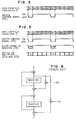
- Fig. 3 shows, by way of example, the timing at which the control signal is generated by the control unit 30.
- the data A1 to A5 and B1 to B5 outputted from the A/D converter 5 represent trains or sequences of Doppler shift signal data obtained from a same location of a living being under test.
- the switch 24 is opened (i.e., set to the OFF-state).
- the switch 24 is closed (ON-state).
- Fig. 4 is a block diagram showing in detail a structure of the wall filter according to a second embodiment of the invention.
- the wall filter according to the instant embodiment differs from that of the first embodiment in that the register 23b sown in Fig. 2 is provided with a zero-clear terminal, whereby the contents of the register 23b is cleared to zero at the timing when the switch 24 is opened.
- Fig. 5 is a timing chart for illustrating operation of the control unit 30 in the apparatus according to the second embodiment of the invention.
- the content of the register 23b is cleared to zero at the time point when the first data of each data sequence is inputted to the filter, whereby the outputs of multipliers 22a and 22b are reset to zero.
- influence of the preceding data sequence is prevented from being fed back.
- the transient response of the filter can further be reduced by virtue of such arrangement that the content of the register of the succeeding stage is cleared to zero every time the first data of the data sequence is inputted in addition to suppression of the transient response of the filter of the preceding stage by means of the control unit 30 and the switch 22.
- the FIR-type filter of first degree is used as the filter 25 of the preceding stage with the IIR-type filter being used in the succeeding stage for implementing the wall filter 20. It should however be understood the filter of IIR type or FIR type may be used in both of the preceding and succeeding stages, substantially to the same effects.
- the filter of degree several may be used as the filters of the preceding and succeeding stages.
- the switch 24 is opened during a period in which the first m data ( m is an integer) to be filtered through the wall filter is inputted, wherein the number m is determined in the manner, as mentioned below.
- the FIR-type filters are disposed in series in the preceding stage in a number n ( n is an integer) at maximum, the number of the registers in the preceding stage is n at maximum in the serial direction.
- the data up to the n-th data in the output data sequence contain the transient response.
- the value of m for which the switch 24 is opened can be selected such that the transient response occurring in the preceding stage can sufficiently be eliminated while an amount of data to be discarded can be minimized.
- the value of m thus determined can previously be set at the control unit 30. Besides, the value now of concern can be changed by issuing corresponding commands to the control unit while observing the picture generated actually in the course of operation of the ultrasonic Doppler blood flow meter apparatus.
- the switch 24 is provided internally of the wall filter 20, it is of course possible to provide it externally of the wall filter 20. Besides, it is of no matter whether or not the switch 24 is implemented integrally with the wall filer 20. What is required is that a filter including the register is disposed at the side upstream of the switch 24.
Landscapes
- Engineering & Computer Science (AREA)
- Physics & Mathematics (AREA)
- Health & Medical Sciences (AREA)
- Remote Sensing (AREA)
- Life Sciences & Earth Sciences (AREA)
- Radar, Positioning & Navigation (AREA)
- Acoustics & Sound (AREA)
- Pathology (AREA)
- Public Health (AREA)
- Biomedical Technology (AREA)
- Heart & Thoracic Surgery (AREA)
- Medical Informatics (AREA)
- Molecular Biology (AREA)
- Surgery (AREA)
- Animal Behavior & Ethology (AREA)
- General Health & Medical Sciences (AREA)
- Radiology & Medical Imaging (AREA)
- Veterinary Medicine (AREA)
- Nuclear Medicine, Radiotherapy & Molecular Imaging (AREA)
- Biophysics (AREA)
- Hematology (AREA)
- Computer Networks & Wireless Communication (AREA)
- General Physics & Mathematics (AREA)
- Ultra Sonic Daignosis Equipment (AREA)
Applications Claiming Priority (3)
| Application Number | Priority Date | Filing Date | Title |
|---|---|---|---|
| JP137285/93 | 1993-06-08 | ||
| JP5137285A JP3000823B2 (ja) | 1993-06-08 | 1993-06-08 | 超音波ドプラ血流計 |
| JP13728593 | 1993-06-08 |
Publications (3)
| Publication Number | Publication Date |
|---|---|
| EP0628285A2 true EP0628285A2 (fr) | 1994-12-14 |
| EP0628285A3 EP0628285A3 (fr) | 1998-04-29 |
| EP0628285B1 EP0628285B1 (fr) | 2002-12-11 |
Family
ID=15195115
Family Applications (1)
| Application Number | Title | Priority Date | Filing Date |
|---|---|---|---|
| EP94301977A Expired - Lifetime EP0628285B1 (fr) | 1993-06-08 | 1994-03-18 | Appareil ultrasonique de mesure de l'écoulement sanguin |
Country Status (4)
| Country | Link |
|---|---|
| US (1) | US5419333A (fr) |
| EP (1) | EP0628285B1 (fr) |
| JP (1) | JP3000823B2 (fr) |
| DE (1) | DE69431860T2 (fr) |
Cited By (2)
| Publication number | Priority date | Publication date | Assignee | Title |
|---|---|---|---|---|
| DE19601321A1 (de) * | 1995-04-18 | 1996-10-24 | Fujitsu Ltd | Ultraschalldiagnostische Vorrichtung |
| WO1999056626A1 (fr) * | 1998-05-05 | 1999-11-11 | Cornell Research Foundation, Inc. | Procede d'evaluation de debit sanguin et appareil associe |
Families Citing this family (4)
| Publication number | Priority date | Publication date | Assignee | Title |
|---|---|---|---|---|
| JP3771978B2 (ja) * | 1996-10-31 | 2006-05-10 | 株式会社東芝 | 超音波診断装置 |
| US5823964A (en) * | 1996-12-30 | 1998-10-20 | Siemens Medical Systems, Inc. | Ultrasound doppler wall filter |
| US6110113A (en) * | 1998-12-15 | 2000-08-29 | Siemens Medical Systems, Inc. | Method and apparatus for removing transients and gaps from ultrasound echo signals |
| US7857763B2 (en) * | 2005-02-08 | 2010-12-28 | Alan Chi-Chung Tai | Automatic signal-optimizing transducer assembly for blood flow measurement |
Family Cites Families (9)
| Publication number | Priority date | Publication date | Assignee | Title |
|---|---|---|---|---|
| US4042924A (en) * | 1970-02-25 | 1977-08-16 | Hughes Aircraft Company | MTI clutter tracking and cancelling system |
| US3787848A (en) * | 1972-08-28 | 1974-01-22 | Hughes Aircraft Co | System for discriminating between high and low speed targets |
| JPS6384532A (ja) * | 1986-09-29 | 1988-04-15 | 株式会社東芝 | 超音波血流観測装置 |
| JPS6385383A (ja) * | 1986-09-29 | 1988-04-15 | Mitsubishi Electric Corp | レ−ダ装置の信号検出装置 |
| JP2772045B2 (ja) * | 1989-07-06 | 1998-07-02 | 株式会社東芝 | 超音波診断装置 |
| JPH03188841A (ja) * | 1989-09-20 | 1991-08-16 | Toshiba Corp | 超音波診断装置 |
| US5211169A (en) * | 1990-11-08 | 1993-05-18 | Prism Imaging, Inc. | Blood pool imaging and analysis technique using ultrasound |
| US5152292A (en) * | 1990-12-20 | 1992-10-06 | Hewlett-Packard Company | Adaptive rejection filter for color flow ultrasound imaging |
| US5269308A (en) * | 1991-07-25 | 1993-12-14 | Matsushita Electric Industrial Co., Ltd. | Ultrasonic doppler imaging apparatus |
-
1993
- 1993-06-08 JP JP5137285A patent/JP3000823B2/ja not_active Expired - Lifetime
-
1994
- 1994-02-28 US US08/202,471 patent/US5419333A/en not_active Expired - Lifetime
- 1994-03-18 DE DE69431860T patent/DE69431860T2/de not_active Expired - Lifetime
- 1994-03-18 EP EP94301977A patent/EP0628285B1/fr not_active Expired - Lifetime
Cited By (4)
| Publication number | Priority date | Publication date | Assignee | Title |
|---|---|---|---|---|
| DE19601321A1 (de) * | 1995-04-18 | 1996-10-24 | Fujitsu Ltd | Ultraschalldiagnostische Vorrichtung |
| DE19601321B4 (de) * | 1995-04-18 | 2005-04-28 | Fukuda Denshi Kk | Ultraschalldiagnosevorrichtung |
| WO1999056626A1 (fr) * | 1998-05-05 | 1999-11-11 | Cornell Research Foundation, Inc. | Procede d'evaluation de debit sanguin et appareil associe |
| US6547731B1 (en) | 1998-05-05 | 2003-04-15 | Cornell Research Foundation, Inc. | Method for assessing blood flow and apparatus thereof |
Also Published As
| Publication number | Publication date |
|---|---|
| JP3000823B2 (ja) | 2000-01-17 |
| JPH06343635A (ja) | 1994-12-20 |
| US5419333A (en) | 1995-05-30 |
| EP0628285A3 (fr) | 1998-04-29 |
| DE69431860T2 (de) | 2003-09-04 |
| DE69431860D1 (de) | 2003-01-23 |
| EP0628285B1 (fr) | 2002-12-11 |
Similar Documents
| Publication | Publication Date | Title |
|---|---|---|
| EP0092841B1 (fr) | Dispositif ultrasonique de diagnostic | |
| US5642732A (en) | Apparatus and method for estimating missing doppler signals and spectra | |
| US4993417A (en) | Method and system for controlling ultrasound scanning sequence | |
| US5676148A (en) | Method and system for doppler ultrasound audio dealiasing | |
| EP0144968A2 (fr) | Appareil de diagnostic à ultrasons | |
| US5467770A (en) | Color adaptive frame averaging | |
| DE19520920A1 (de) | Verfahren zum Bestimmen des Geschwindigkeit-Zeit-Spektrums einer Blutströmung | |
| US6210334B1 (en) | Medical diagnostic ultrasound method and apparatus for harmonic detection using doppler processing | |
| US6773403B2 (en) | Ultrasonic apparatus and method for measuring the velocities of human tissues using the doppler effects | |
| DE69031747T2 (de) | Kompensierter Detektor für bewegte Ziele mit veränderlicher Wiederholungsfrequenz | |
| EP0042288B1 (fr) | Appareil pour la représentation d'images au moyen d'ultrasons | |
| EP0228070A2 (fr) | Dispositif diagnostique ultrasonique à effet Doppler | |
| US5269308A (en) | Ultrasonic doppler imaging apparatus | |
| US5419333A (en) | Ultrasonic doppler blood flow meter apparatus | |
| DE3687384T2 (de) | Ultraschallgeraet zur messung der beschleunigung eines bewegten reflektierenden teils. | |
| EP0375441B1 (fr) | Appareil pour la détection des vitesses d'écoulement du sang par effet Doppler à ultrasons | |
| US5718230A (en) | Method and apparatus for creating ultrasound images using a reduced number of transmit beam lines | |
| EP0488545B1 (fr) | Debitmètre sanguin à ultrasons et effet Doppler | |
| DE69222401T2 (de) | Ultraschallechograph zur Messung hoher Geschwindigkeiten von Blutströmungen | |
| US4883060A (en) | Device for eliminating fixed echoes for an ultrasonic echograph | |
| KR0178095B1 (ko) | 초음파 칼라 도플러 영상시스템을 위한 필터링방법 | |
| JPH0693892B2 (ja) | 超音波エコ−グラフィによる物体走査装置 | |
| US5588433A (en) | Ultrasonic diagnostic apparatus | |
| US6361498B1 (en) | Contrast agent imaging with suppression of nonlinear tissue response | |
| JP3642834B2 (ja) | 超音波ドプラ診断装置 |
Legal Events
| Date | Code | Title | Description |
|---|---|---|---|
| PUAI | Public reference made under article 153(3) epc to a published international application that has entered the european phase |
Free format text: ORIGINAL CODE: 0009012 |
|
| 17P | Request for examination filed |
Effective date: 19940326 |
|
| AK | Designated contracting states |
Kind code of ref document: A2 Designated state(s): DE FR GB |
|
| PUAL | Search report despatched |
Free format text: ORIGINAL CODE: 0009013 |
|
| AK | Designated contracting states |
Kind code of ref document: A3 Designated state(s): DE FR GB |
|
| 17Q | First examination report despatched |
Effective date: 20000331 |
|
| GRAG | Despatch of communication of intention to grant |
Free format text: ORIGINAL CODE: EPIDOS AGRA |
|
| GRAG | Despatch of communication of intention to grant |
Free format text: ORIGINAL CODE: EPIDOS AGRA |
|
| GRAH | Despatch of communication of intention to grant a patent |
Free format text: ORIGINAL CODE: EPIDOS IGRA |
|
| GRAH | Despatch of communication of intention to grant a patent |
Free format text: ORIGINAL CODE: EPIDOS IGRA |
|
| GRAA | (expected) grant |
Free format text: ORIGINAL CODE: 0009210 |
|
| AK | Designated contracting states |
Kind code of ref document: B1 Designated state(s): DE FR GB |
|
| REG | Reference to a national code |
Ref country code: GB Ref legal event code: FG4D |
|
| REF | Corresponds to: |
Ref document number: 69431860 Country of ref document: DE Date of ref document: 20030123 |
|
| ET | Fr: translation filed | ||
| PLBE | No opposition filed within time limit |
Free format text: ORIGINAL CODE: 0009261 |
|
| STAA | Information on the status of an ep patent application or granted ep patent |
Free format text: STATUS: NO OPPOSITION FILED WITHIN TIME LIMIT |
|
| 26N | No opposition filed |
Effective date: 20030912 |
|
| PGFP | Annual fee paid to national office [announced via postgrant information from national office to epo] |
Ref country code: FR Payment date: 20130325 Year of fee payment: 20 Ref country code: GB Payment date: 20130313 Year of fee payment: 20 Ref country code: DE Payment date: 20130314 Year of fee payment: 20 |
|
| REG | Reference to a national code |
Ref country code: FR Ref legal event code: CD Owner name: PANASONIC CORPORATION, JP Effective date: 20131106 |
|
| REG | Reference to a national code |
Ref country code: DE Ref legal event code: R071 Ref document number: 69431860 Country of ref document: DE |
|
| REG | Reference to a national code |
Ref country code: GB Ref legal event code: PE20 Expiry date: 20140317 |
|
| PG25 | Lapsed in a contracting state [announced via postgrant information from national office to epo] |
Ref country code: DE Free format text: LAPSE BECAUSE OF EXPIRATION OF PROTECTION Effective date: 20140319 Ref country code: GB Free format text: LAPSE BECAUSE OF EXPIRATION OF PROTECTION Effective date: 20140317 |
|
| REG | Reference to a national code |
Ref country code: FR Ref legal event code: TP Owner name: KONICA MINOLTA, INC., JP Effective date: 20140428 |