EP0628693B1 - Equerre, en particulier pour palier au moins pivotant d'une aile, d'une fenêtre, d'une porte ou similaire - Google Patents
Equerre, en particulier pour palier au moins pivotant d'une aile, d'une fenêtre, d'une porte ou similaire Download PDFInfo
- Publication number
- EP0628693B1 EP0628693B1 EP94108786A EP94108786A EP0628693B1 EP 0628693 B1 EP0628693 B1 EP 0628693B1 EP 94108786 A EP94108786 A EP 94108786A EP 94108786 A EP94108786 A EP 94108786A EP 0628693 B1 EP0628693 B1 EP 0628693B1
- Authority
- EP
- European Patent Office
- Prior art keywords
- corner
- corner angle
- groove
- angle support
- bent
- Prior art date
- Legal status (The legal status is an assumption and is not a legal conclusion. Google has not performed a legal analysis and makes no representation as to the accuracy of the status listed.)
- Expired - Lifetime
Links
- 239000011324 bead Substances 0.000 claims description 6
- 238000003466 welding Methods 0.000 claims description 2
- 238000010008 shearing Methods 0.000 abstract 1
- 238000005452 bending Methods 0.000 description 7
- 239000000463 material Substances 0.000 description 2
- 230000007704 transition Effects 0.000 description 2
- 230000002159 abnormal effect Effects 0.000 description 1
- 238000010438 heat treatment Methods 0.000 description 1
- 238000004519 manufacturing process Methods 0.000 description 1
- 238000000034 method Methods 0.000 description 1
- 230000000284 resting effect Effects 0.000 description 1
- 238000002604 ultrasonography Methods 0.000 description 1
Images
Classifications
-
- E—FIXED CONSTRUCTIONS
- E05—LOCKS; KEYS; WINDOW OR DOOR FITTINGS; SAFES
- E05D—HINGES OR SUSPENSION DEVICES FOR DOORS, WINDOWS OR WINGS
- E05D15/00—Suspension arrangements for wings
- E05D15/48—Suspension arrangements for wings allowing alternative movements
- E05D15/52—Suspension arrangements for wings allowing alternative movements for opening about a vertical as well as a horizontal axis
- E05D15/5214—Corner supports
-
- E—FIXED CONSTRUCTIONS
- E05—LOCKS; KEYS; WINDOW OR DOOR FITTINGS; SAFES
- E05Y—INDEXING SCHEME ASSOCIATED WITH SUBCLASSES E05D AND E05F, RELATING TO CONSTRUCTION ELEMENTS, ELECTRIC CONTROL, POWER SUPPLY, POWER SIGNAL OR TRANSMISSION, USER INTERFACES, MOUNTING OR COUPLING, DETAILS, ACCESSORIES, AUXILIARY OPERATIONS NOT OTHERWISE PROVIDED FOR, APPLICATION THEREOF
- E05Y2900/00—Application of doors, windows, wings or fittings thereof
- E05Y2900/10—Application of doors, windows, wings or fittings thereof for buildings or parts thereof
- E05Y2900/13—Type of wing
- E05Y2900/148—Windows
Definitions
- the invention relates to a corner bracket on or for a fitting part of a fitting, in particular for the at least rotatable mounting of a sash, a window, a door or the like on a fixed frame, the sash having at least in the region of the frame corner receiving the corner bracket is provided against the fixed frame towards the outside, widening the fitting part groove on the outside, the corner angle also resting on the two parallel shoulders of the fitting part groove and being fastened to the wing by means of screws screwed into the groove base.
- a corner angle is known from EP-A-0 204 267.
- the fitting part groove usually runs around on the casement, so that one and the same profile can be used for the frame bars.
- the cross section of the fitting part groove depends on the fitting to be fitted.
- the step-by-step narrowing can, as provided in the exemplary embodiment, be achieved by providing two parallel, mutually facing webs shortly before the slot mouth. The corner angle then lies on the outer edge of the two webs, it again being customary for the corner angle to be flush with the wing on the outside.
- the corner bracket is used to attach fittings, for example a bearing sleeve of a pivot bearing for the at least rotatable mounting of this wing on a fixed frame receiving the latter.
- fittings for example a bearing sleeve of a pivot bearing for the at least rotatable mounting of this wing on a fixed frame receiving the latter.
- the groove width at the mouth of the groove generally corresponds to the width of the angle leg of the corner bracket, so that the groove at the corner in question is closed smoothly on the outside by the corner bracket.
- An extension plate can be attached to each angle leg, which then closes the remaining part of the groove on the outside.
- each leg of the corner angle of the known prior art has a certain distance from the base of the groove and the fastening screws penetrate the groove to the groove base and then penetrate into the groove base, whereby the connection to the relevant spar of the casement takes place, the load on the screws is particularly unfavorable.
- the screws that are initially screwed in tightly can loosen somewhat, and this then leads to bending stress not only in the event of violence, but also when the window or door is subsequently used of the screws.
- at least some of the screws can loosen further, and this will result in an overall compromise in safety.
- the object is to develop a corner bracket of the type mentioned at the outset so that, at least in the cases described, the bending stress on the screws is at least largely avoided.
- this corner bracket has, as it were, a supporting element for supporting on the base of the groove, which in addition to the non-deformed angled leg of at least one Fastening screw is penetrated.
- the screw is thus subjected to shear at the groove base and not to bending as before.
- a screw is always more resilient to shear than to a bend, and as a result, this corner angle, in the desired manner, brings about a significant improvement in safety when abnormal conditions occur, which also includes excessive heating of the wing.
- the width of the end areas must of course be chosen so that they fit through the respective narrow point between the two support edges in the groove and, if the groove narrows further inside, the passage to the groove base is also possible there. In most cases, the narrow point between the two support edges is the narrowest point of the groove, so that a one-time reduction in the width, in particular before bending, is sufficient.
- the total height of the angle legs in the region of the bent ends is equal to the total depth of the groove. It follows from this that the bent ends of the angled legs generally have an arcuate or U-shaped shape and the corner angle is not simply folded.
- a further development of the invention provides that the width of the corner angle in the area of the immediate corner corner is reduced by means of two opposite cutouts, the size of the cutouts corresponding approximately to the cross section of a weld bead on the outer corner of the frame.
- the depth of the cutouts can correspond approximately to the reduction in the width on each side of the end region to be bent or, in other words, the width of the corner angle in the region of the immediate corner corner is approximately equal to the width of the two bent end regions.
- the bearing sleeve can be connected indirectly via an angular intermediate member to the upper angle leg in the position of use, whereby an articulated connection known per se can also be present, so that the bearing sleeve can be pivoted relative to the sash frame level.
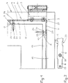
- the corner bracket 1 forms the one in the embodiment together with a bearing sleeve 2 or the wing-side half of a lower pivot bearing 3.
- the wing 4 is rotatably supported in a manner not shown with the help of an upper and the lower pivot bearing on a fixed frame. It can also be a turn-tilt wing.
- the corner bracket has two angle brackets 5 and 6 which run perpendicular to one another.
- the lower, horizontal angle bracket 6 in the use position is shorter than the vertical angle bracket 5. This is common with such corner brackets, but this does not rule out that both angle brackets are the same are long.
- the end regions 7 and 8 of the two angle legs are bent inwards by approximately 180 °.
- these end regions are not simply folded; rather, together with the part of the respective angle leg that has remained undeformed, they form cross-sectionally arched or U-shaped supporting elements.
- Figure 2 which represents the angle leg before bending, it can be seen that the width of the corner angle material is reduced at the two ends.
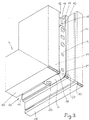
- the reduced part forms a support element 9 or 10 after the two bends by 90 ° each, with which the corner angle on the groove base 11 of a groove 12 of the vertical frame spar 14 and a horizontal groove 13 of the supports horizontal spar 15 of the wing 4. It can be seen from FIG.
- each angled leg rests on the outwardly facing edge 16 of two mutually facing strips 17, the space between the two strips, of which only the right one can be seen in FIG. 3, forms a groove constriction 18.
- the outer surface of the two angle legs each runs flush with the associated spar surface 19 and 20.
- the grooves 12 and 13 are fitting grooves which, for example, accommodate drive rods in a known manner. Due to the mentioned narrowing of the groove, one can also speak of a fitting part groove 12 or 13 which is widened in sections on the outside. Moreover, it is common for the fitting part grooves 12 and 13 to be parts of a circumferential fitting part groove of the wing 4.
- the free end 21 or 22 of the bent end region 7 or 8 runs approximately parallel to the undeformed part of its angle leg 5 or 6 and is supported directly on the groove base 11.
- the free end 21 or 22 is provided with a through hole 23 for the passage of a fastening screw 24, which also passes through a coaxial through hole 25 of the undeformed angled leg and enters the material of the associated frame spar at the groove base.
- a cutout 26 or 27 is provided on both sides, that is, at the location of the corner angle 1, which forms the immediate corner corner 29 after bending.
- the width of the corner angle is approximately equal to that of the end regions 7 and 8.
Landscapes
- Engineering & Computer Science (AREA)
- Mechanical Engineering (AREA)
- Hinges (AREA)
- Wing Frames And Configurations (AREA)
- Joining Of Corner Units Of Frames Or Wings (AREA)
- Door And Window Frames Mounted To Openings (AREA)
- Assembled Shelves (AREA)
Claims (3)
- Equerre d'angle (1) sur - ou pour - un élément de ferrure pour ferrage, en particulier pour l'appui au moins pivotant d'un vantail (4), d'une fenêtre, d'une porte ou similaire, sur un dormant, le vantail comportant, au moins au niveau de l'angle de cadre recevant l'équerre d'angle (1), une rainure d'élément de ferrure (12, 13) ouverte en direction du dormant et s'élargissant en gradin vers l'extérieur, l'équerre d'angle (1) reposant, en outre, sur les deux épaulements parallèles (16) de la rainure d'élément de ferrure (12, 13) et étant fixée sur le vantail (4) au moyen de vis placées en fond de rainure (11), caractérisée en ce que les extrémités (7, 8) des ailes d'équerre (5, 6) de l'équerre d'angle (1) sont recourbées vers l'intérieur de 180° environ, de telle sorte que l'extrémité libre (21, 22) de la partie recourbée (7, 8) est pratiquement parallèle à la partie de l'aile d'équerre (5, 6) dont la forme n'a pas été modifié et est orientée en direction de l'autre aile d'équerre correspondante (6, 5), et en ce que l'extrémité libre (21, 22) de l'aile et la partie non modifiée de l'aile d'équerre comportent des trous traversants alignés (23, 25) prévus pour recevoir chacun une vis de fixation (24), la largeur de la partie recourbée (7, 8), lorsque l'équerre d'angle est en position de service, correspond à peu près à la largeur de la rainure au niveau du rétrécissement en gradin de la rainure (18), l'extrémité libre (21, 22) de la partie recourbée (7, 8) étant en appui sur le fond de rainure (11).
- Equerre d'angle selon la revendication 1, caractérisée en ce que la largeur de l'équerre d'angle (1) juste au niveau de l'angle d'équerre (29) est réduite par la présence de deux dégagements (26, 27) situés de part et d'autre, la taille des dégagements correspondant à peu près à la section d'un bourrelet de soudage (30) de l'angle externe du cadre (4).
- Equerre d'angle selon l'une ou l'autre des revendications 1 et 2, caractérisée en ce que sur l'aile d'équerre (5) disposée verticalement en position de service, il est prévu au moins un manchon de palier (2) pour constituer la moitié (3) d'un palier de pivotement.
Applications Claiming Priority (2)
| Application Number | Priority Date | Filing Date | Title |
|---|---|---|---|
| DE9308670U DE9308670U1 (de) | 1993-06-10 | 1993-06-10 | Eckwinkel, insbesondere für die wenigstens drehbare Lagerung eines Flügels, eines Fensters, einer Tür o.dgl. |
| DE9308670U | 1993-06-10 |
Publications (4)
| Publication Number | Publication Date |
|---|---|
| EP0628693A2 EP0628693A2 (fr) | 1994-12-14 |
| EP0628693A3 EP0628693A3 (fr) | 1995-06-14 |
| EP0628693B1 true EP0628693B1 (fr) | 1996-11-20 |
| EP0628693B2 EP0628693B2 (fr) | 2006-01-04 |
Family
ID=6894266
Family Applications (1)
| Application Number | Title | Priority Date | Filing Date |
|---|---|---|---|
| EP94108786A Expired - Lifetime EP0628693B2 (fr) | 1993-06-10 | 1994-06-08 | Equerre, en particulier pour palier au moins pivotant d'une aile, d'une fenêtre, d'une porte ou similaire |
Country Status (4)
| Country | Link |
|---|---|
| EP (1) | EP0628693B2 (fr) |
| AT (1) | ATE145446T1 (fr) |
| DE (2) | DE9308670U1 (fr) |
| ES (1) | ES2095702T5 (fr) |
Families Citing this family (3)
| Publication number | Priority date | Publication date | Assignee | Title |
|---|---|---|---|---|
| DE29511756U1 (de) * | 1995-07-20 | 1995-09-28 | Ferco International Usine de Ferrures de Bâtiment S.A.R.L., Sarrebourg | Flügelseitiges Ecklagerbeschlagteil für Drehkippfenster |
| DE19707496A1 (de) * | 1997-02-25 | 1998-08-27 | Winkhaus Fa August | Flügellagerteil |
| DE29707358U1 (de) * | 1997-04-23 | 1998-08-27 | Ferco International Ferrures et Serrures de Bâtiment S.A., Reding | Beschlag mit Tragarm oder Ausstellarm zur Lagerung eines Drehflügels oder Dreh-Kippflügels |
Family Cites Families (3)
| Publication number | Priority date | Publication date | Assignee | Title |
|---|---|---|---|---|
| DE8413144U1 (de) † | 1984-04-28 | 1984-07-26 | Gretsch-Unitas GmbH Baubeschläge, 7257 Ditzingen | Fluegelseitiges gelenkband fuer ein fenster, eine tuer od. dgl. |
| DE8516560U1 (de) * | 1985-06-07 | 1985-07-18 | Siegenia-Frank Kg, 5900 Siegen | Ausstellvorrichtung für die Flügel von Fenstern, Türen od. dgl. |
| DE4102295C1 (fr) † | 1991-01-26 | 1992-03-12 | August Bilstein Gmbh & Co. Kg, 5828 Ennepetal, De |
-
1993
- 1993-06-10 DE DE9308670U patent/DE9308670U1/de not_active Expired - Lifetime
-
1994
- 1994-06-08 EP EP94108786A patent/EP0628693B2/fr not_active Expired - Lifetime
- 1994-06-08 AT AT94108786T patent/ATE145446T1/de not_active IP Right Cessation
- 1994-06-08 DE DE59401063T patent/DE59401063D1/de not_active Expired - Fee Related
- 1994-06-08 ES ES94108786T patent/ES2095702T5/es not_active Expired - Lifetime
Also Published As
| Publication number | Publication date |
|---|---|
| DE9308670U1 (de) | 1994-10-27 |
| EP0628693A3 (fr) | 1995-06-14 |
| ES2095702T3 (es) | 1997-02-16 |
| EP0628693B2 (fr) | 2006-01-04 |
| EP0628693A2 (fr) | 1994-12-14 |
| ES2095702T5 (es) | 2006-06-01 |
| DE59401063D1 (de) | 1997-01-02 |
| ATE145446T1 (de) | 1996-12-15 |
Similar Documents
| Publication | Publication Date | Title |
|---|---|---|
| EP3504391B1 (fr) | Ensemble charnière pour un boitier d'armoire électrique et un boitier d'armoire électrique correspondant | |
| DE102007028218B3 (de) | Tür- oder Fensterscharnier | |
| EP0995001B1 (fr) | Agencement d'une ferrure montee sur un cadre | |
| EP1500768B1 (fr) | Dispositif de support et de fixation d'encadrements pour portes ou fenêtres à la périphérie d'une ouverture de paroi | |
| EP1255012B1 (fr) | Dispositif pour fixer un élément sur un profilé extrudé | |
| EP0947654A1 (fr) | Charnière cachée | |
| DE2460402B2 (de) | Ausstellvorrichtung für Drehkippflügel von Fenstern, Türen o.dgl. | |
| EP0740043A2 (fr) | Arrangement d'une porte à feuillure à droite et à gauche avec châssis et vantail de porte | |
| EP0628693B2 (fr) | Equerre, en particulier pour palier au moins pivotant d'une aile, d'une fenêtre, d'une porte ou similaire | |
| EP2065546B2 (fr) | Ferrure de charnière destinée à la fixation pivotante du cadre d'un volet | |
| EP0563550B1 (fr) | Ferrure pour fenêtre ou porte pivotante autour son axe central | |
| EP0312738B1 (fr) | Armature pour un battant de fenêtre, de porte ou des choses pareilles orientable au moins en bas et fenêtre ou porte munie de cette armature | |
| EP1441096B1 (fr) | Dispositif de fixation pour une ferrure | |
| EP1001124A1 (fr) | Ferrure de charnière pour un volet | |
| EP1550786B1 (fr) | Dormant, notamment pour porte | |
| DE202011052447U1 (de) | Anordnung einer Antriebseinheit einer Ausstell- oder Verriegelungseinrichtung | |
| EP1391576B1 (fr) | Compensation de la torsion de battants pouvant être déplacés d'un plan vers un autre plan parallèle | |
| DE10005074C2 (de) | Einrichtung zur Anordnung in einem Spalt zwischen einem Rahmen und einem Flügel | |
| EP3348731B1 (fr) | Construction à poteaux-traverses | |
| DE29811017U1 (de) | Befestigung eines Beschlagteils | |
| EP4446552B1 (fr) | Battant mobile par rapport à un dormant d'une fenêtre ou d'une porte et procédé de fixation de deux profilés principaux | |
| DE102005053650B3 (de) | Scharnierbeschlag | |
| EP2025845A1 (fr) | Ferrure de charnière d'une fenêtre, d'une porte ou analogue dotée d'une goupille oblique | |
| DE19927719A1 (de) | Einrichtung zur Anordnung in einem Spalt zwischen einem Rahmen und einem Flügel | |
| EP4390048A1 (fr) | Cadre pour un dispositif de protection |
Legal Events
| Date | Code | Title | Description |
|---|---|---|---|
| PUAI | Public reference made under article 153(3) epc to a published international application that has entered the european phase |
Free format text: ORIGINAL CODE: 0009012 |
|
| AK | Designated contracting states |
Kind code of ref document: A2 Designated state(s): AT BE CH DE ES FR GB IT LI NL |
|
| PUAL | Search report despatched |
Free format text: ORIGINAL CODE: 0009013 |
|
| AK | Designated contracting states |
Kind code of ref document: A3 Designated state(s): AT BE CH DE ES FR GB IT LI NL |
|
| 17P | Request for examination filed |
Effective date: 19950629 |
|
| GRAG | Despatch of communication of intention to grant |
Free format text: ORIGINAL CODE: EPIDOS AGRA |
|
| GRAH | Despatch of communication of intention to grant a patent |
Free format text: ORIGINAL CODE: EPIDOS IGRA |
|
| 17Q | First examination report despatched |
Effective date: 19960416 |
|
| GRAH | Despatch of communication of intention to grant a patent |
Free format text: ORIGINAL CODE: EPIDOS IGRA |
|
| GRAA | (expected) grant |
Free format text: ORIGINAL CODE: 0009210 |
|
| AK | Designated contracting states |
Kind code of ref document: B1 Designated state(s): AT BE CH DE ES FR GB IT LI NL |
|
| REF | Corresponds to: |
Ref document number: 145446 Country of ref document: AT Date of ref document: 19961215 Kind code of ref document: T |
|
| ITF | It: translation for a ep patent filed | ||
| REG | Reference to a national code |
Ref country code: CH Ref legal event code: NV Representative=s name: TROESCH SCHEIDEGGER WERNER AG |
|
| GBT | Gb: translation of ep patent filed (gb section 77(6)(a)/1977) |
Effective date: 19961115 |
|
| REF | Corresponds to: |
Ref document number: 59401063 Country of ref document: DE Date of ref document: 19970102 |
|
| ET | Fr: translation filed | ||
| REG | Reference to a national code |
Ref country code: ES Ref legal event code: FG2A Ref document number: 2095702 Country of ref document: ES Kind code of ref document: T3 |
|
| PLBI | Opposition filed |
Free format text: ORIGINAL CODE: 0009260 |
|
| PLBF | Reply of patent proprietor to notice(s) of opposition |
Free format text: ORIGINAL CODE: EPIDOS OBSO |
|
| 26 | Opposition filed |
Opponent name: SIEGENIA-FRANK KG Effective date: 19970816 |
|
| NLR1 | Nl: opposition has been filed with the epo |
Opponent name: SIEGENIA-FRANK KG |
|
| PLBF | Reply of patent proprietor to notice(s) of opposition |
Free format text: ORIGINAL CODE: EPIDOS OBSO |
|
| REG | Reference to a national code |
Ref country code: GB Ref legal event code: IF02 |
|
| PLAB | Opposition data, opponent's data or that of the opponent's representative modified |
Free format text: ORIGINAL CODE: 0009299OPPO |
|
| R26 | Opposition filed (corrected) |
Opponent name: SIEGENIA-AUBI KG Effective date: 19970816 |
|
| PLBC | Reply to examination report in opposition received |
Free format text: ORIGINAL CODE: EPIDOSNORE3 |
|
| PUAH | Patent maintained in amended form |
Free format text: ORIGINAL CODE: 0009272 |
|
| STAA | Information on the status of an ep patent application or granted ep patent |
Free format text: STATUS: PATENT MAINTAINED AS AMENDED |
|
| 27A | Patent maintained in amended form |
Effective date: 20060104 |
|
| AK | Designated contracting states |
Kind code of ref document: B2 Designated state(s): AT BE CH DE ES FR GB IT LI NL |
|
| GBTA | Gb: translation of amended ep patent filed (gb section 77(6)(b)/1977) | ||
| REG | Reference to a national code |
Ref country code: CH Ref legal event code: AEN Free format text: AUFRECHTERHALTUNG DES PATENTES IN GEAENDERTER FORM |
|
| NLR2 | Nl: decision of opposition |
Effective date: 20060104 |
|
| NLR3 | Nl: receipt of modified translations in the netherlands language after an opposition procedure | ||
| REG | Reference to a national code |
Ref country code: ES Ref legal event code: DC2A Date of ref document: 20060216 Kind code of ref document: T5 |
|
| ET3 | Fr: translation filed ** decision concerning opposition | ||
| PGFP | Annual fee paid to national office [announced via postgrant information from national office to epo] |
Ref country code: NL Payment date: 20070615 Year of fee payment: 14 Ref country code: CH Payment date: 20070615 Year of fee payment: 14 |
|
| PGFP | Annual fee paid to national office [announced via postgrant information from national office to epo] |
Ref country code: AT Payment date: 20070618 Year of fee payment: 14 |
|
| PGFP | Annual fee paid to national office [announced via postgrant information from national office to epo] |
Ref country code: ES Payment date: 20070628 Year of fee payment: 14 |
|
| PGFP | Annual fee paid to national office [announced via postgrant information from national office to epo] |
Ref country code: GB Payment date: 20070621 Year of fee payment: 14 |
|
| PGFP | Annual fee paid to national office [announced via postgrant information from national office to epo] |
Ref country code: IT Payment date: 20070626 Year of fee payment: 14 |
|
| PGFP | Annual fee paid to national office [announced via postgrant information from national office to epo] |
Ref country code: BE Payment date: 20070711 Year of fee payment: 14 |
|
| PGFP | Annual fee paid to national office [announced via postgrant information from national office to epo] |
Ref country code: FR Payment date: 20070615 Year of fee payment: 14 |
|
| PGFP | Annual fee paid to national office [announced via postgrant information from national office to epo] |
Ref country code: DE Payment date: 20080620 Year of fee payment: 15 |
|
| BERE | Be: lapsed |
Owner name: *GRETSCH-UNITAS G.M.B.H. BAUBESCHLAGE Effective date: 20080630 |
|
| REG | Reference to a national code |
Ref country code: CH Ref legal event code: PL |
|
| GBPC | Gb: european patent ceased through non-payment of renewal fee |
Effective date: 20080608 |
|
| NLV4 | Nl: lapsed or anulled due to non-payment of the annual fee |
Effective date: 20090101 |
|
| PG25 | Lapsed in a contracting state [announced via postgrant information from national office to epo] |
Ref country code: BE Free format text: LAPSE BECAUSE OF NON-PAYMENT OF DUE FEES Effective date: 20080630 |
|
| REG | Reference to a national code |
Ref country code: FR Ref legal event code: ST Effective date: 20090228 |
|
| PG25 | Lapsed in a contracting state [announced via postgrant information from national office to epo] |
Ref country code: AT Free format text: LAPSE BECAUSE OF NON-PAYMENT OF DUE FEES Effective date: 20080608 |
|
| PG25 | Lapsed in a contracting state [announced via postgrant information from national office to epo] |
Ref country code: NL Free format text: LAPSE BECAUSE OF NON-PAYMENT OF DUE FEES Effective date: 20090101 |
|
| PG25 | Lapsed in a contracting state [announced via postgrant information from national office to epo] |
Ref country code: LI Free format text: LAPSE BECAUSE OF NON-PAYMENT OF DUE FEES Effective date: 20080630 Ref country code: GB Free format text: LAPSE BECAUSE OF NON-PAYMENT OF DUE FEES Effective date: 20080608 Ref country code: CH Free format text: LAPSE BECAUSE OF NON-PAYMENT OF DUE FEES Effective date: 20080630 |
|
| REG | Reference to a national code |
Ref country code: ES Ref legal event code: FD2A Effective date: 20080609 |
|
| PG25 | Lapsed in a contracting state [announced via postgrant information from national office to epo] |
Ref country code: IT Free format text: LAPSE BECAUSE OF NON-PAYMENT OF DUE FEES Effective date: 20080608 Ref country code: FR Free format text: LAPSE BECAUSE OF NON-PAYMENT OF DUE FEES Effective date: 20080630 |
|
| PG25 | Lapsed in a contracting state [announced via postgrant information from national office to epo] |
Ref country code: ES Free format text: LAPSE BECAUSE OF NON-PAYMENT OF DUE FEES Effective date: 20080609 |
|
| PG25 | Lapsed in a contracting state [announced via postgrant information from national office to epo] |
Ref country code: DE Free format text: LAPSE BECAUSE OF NON-PAYMENT OF DUE FEES Effective date: 20100101 |