EP0628721B1 - Radialkolbenpumpe - Google Patents
Radialkolbenpumpe Download PDFInfo
- Publication number
- EP0628721B1 EP0628721B1 EP94201695A EP94201695A EP0628721B1 EP 0628721 B1 EP0628721 B1 EP 0628721B1 EP 94201695 A EP94201695 A EP 94201695A EP 94201695 A EP94201695 A EP 94201695A EP 0628721 B1 EP0628721 B1 EP 0628721B1
- Authority
- EP
- European Patent Office
- Prior art keywords
- passage
- pressure
- circumferential
- radial
- cylinders
- Prior art date
- Legal status (The legal status is an assumption and is not a legal conclusion. Google has not performed a legal analysis and makes no representation as to the accuracy of the status listed.)
- Expired - Lifetime
Links
- 239000000463 material Substances 0.000 claims abstract description 7
- 229920003023 plastic Polymers 0.000 claims abstract description 7
- 239000004033 plastic Substances 0.000 claims abstract description 7
- 239000007788 liquid Substances 0.000 claims abstract description 5
- 230000002093 peripheral effect Effects 0.000 claims 2
- 230000008878 coupling Effects 0.000 description 4
- 238000010168 coupling process Methods 0.000 description 4
- 238000005859 coupling reaction Methods 0.000 description 4
- 238000005086 pumping Methods 0.000 description 2
- 239000011347 resin Substances 0.000 description 2
- 229920005989 resin Polymers 0.000 description 2
- 238000007789 sealing Methods 0.000 description 2
- 238000010276 construction Methods 0.000 description 1
- 239000012530 fluid Substances 0.000 description 1
Images
Classifications
-
- F—MECHANICAL ENGINEERING; LIGHTING; HEATING; WEAPONS; BLASTING
- F04—POSITIVE - DISPLACEMENT MACHINES FOR LIQUIDS; PUMPS FOR LIQUIDS OR ELASTIC FLUIDS
- F04B—POSITIVE-DISPLACEMENT MACHINES FOR LIQUIDS; PUMPS
- F04B1/00—Multi-cylinder machines or pumps characterised by number or arrangement of cylinders
- F04B1/04—Multi-cylinder machines or pumps characterised by number or arrangement of cylinders having cylinders in star- or fan-arrangement
-
- F—MECHANICAL ENGINEERING; LIGHTING; HEATING; WEAPONS; BLASTING
- F04—POSITIVE - DISPLACEMENT MACHINES FOR LIQUIDS; PUMPS FOR LIQUIDS OR ELASTIC FLUIDS
- F04B—POSITIVE-DISPLACEMENT MACHINES FOR LIQUIDS; PUMPS
- F04B1/00—Multi-cylinder machines or pumps characterised by number or arrangement of cylinders
- F04B1/04—Multi-cylinder machines or pumps characterised by number or arrangement of cylinders having cylinders in star- or fan-arrangement
- F04B1/0404—Details or component parts
- F04B1/0452—Distribution members, e.g. valves
Definitions
- the invention relates to a radial piston pump as defined in the first part of claim 1.
- annular wall portion surrounding the pump body is intended to close the circumferential pressure passage at the outer circumference thereof.
- the tightness of the circumferential passage as a pressure passage is completely determined by sealing rings provided in circumferential grooves on either side of the circumferential pressure passage.
- the invention aims at providing an improved pump of the above type, which is suitable for higher pump pressures (up to 1000 bar) and which is of a compact and lightweight construction, which is of particular importance for use in hydraulically operated tools.
- the annular member of plastics material Due to the trapezium-shaped cross-section of the annular member of plastics material in its tension free state, the annular member will tend to slightly bulge convexly outwardly beyond the circumferential outer surface of the pump body.
- the annular wall portion will cause the annular member of plastics material to return to a flat shape (as seen in the axial direction), due to which the annular member will be pressed with its opposite end faces firmly against the opposite sidewalls of the circumferential passage.
- the pressure of the annular member of plastics material against the sidewalls of the circumferential pressure passage will be further increased by the pressure prevailing within the inner circumferential groove of the annular member, said pressure tending to bend the end wall portions on either side of said groove axially outwardly.
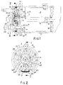
- the annular pump body 1 is surrounded by an annular wall member 2 and has a number of radially directed pumping cylinders 3, in which pistons 4 are mounted for a reciprocating movement.
- the pump body 1 confines a central space 5, into which the radial inner ends project and which also accommodates the excentric part 8 of the rotor 7; the radial inner piston ends broaden into heads 6.
- One end (i.e. the left end as seen in fig. 1) of the central space 5 (fig. 3) is closed by a cover 10 and at a distance from the latter within the pump body 1 ball bearings 11 and 12 are provided, in which the centric portion 9, 9a of the rotor 7 is journalled.
- a connecting shaft made e.g. of a suitable artificial resin, one end of which non-rotatably engages a central bore 14 in the centrical portion 9 of the rotor 7 and the other end of which non-rotatably engages the drive shaft 15 of the pump engine (electric motor) 16.
- the space between the pump body 1 and the housing of the electric motor 16 is radially outwardly confined by a shell 17, which is an extension of the annular wall member 2 and constitutes the outer wall of a reservoir 18 for the liquid to be pumped.
- Liquid may flow from the reservoir 18 through a filter 19 into a suction passage 30 and through suction openings 20 into each of the cylinders 3; the suction passage 30 is constituted by a circumferential groove of a relatively large depth.
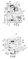
- the radial outer ends of the cylinders 3 merge into a circumferential passage 21 that is provided in the outer wall of the pump body 1.
- the connecting openings between the cylinders 3 and the circumferential passage 21 are broadened into chambers 22 for disc-shaped pressure valves 23.
- the pressure valves 23 are pressed on their seats by means of a common resilient closure element, that is received within the circumferential passage 21 and is constituted by a tangentially pre-stressed O-ring 24; the tangential pre-tension of the ring 24 produces a radially inwardly directed closing force on each of the pressure valves 23.
- the circumferential passage 21 is radially outwardly closed by an annular member 31 of plastics material, having at its circumferential inner surface a groove for receiving the O-ring 24; a radially directed connecting passage 28 (fig. 2), which may be selected rather arbitrarily, connects the circumferential passage 21 to a connection 29 for a pressure line that is provided on the end wall of the pump body 1.
- the annular member 31 of plastics material has a trapezium-shaped cross-section, the longer parallel side of which faces radially inwardly. This shape contributes to a very reliable sealing of the annular member relative to the two sidewalls of the circumferential passage, thereby enabling pumping pressures up to 1000 bar.
- Another radial branch of the circumferential pressure passage 21 is indicated at 32; it connects the circumferential passage to the space 5 and intersects an axial bore for a relief valve-control member 33 (vide fig. 4).
- the connecting opening between the pasage 32 and the circumferential passage 21 is, in a manner similar to the connecting opening of the cylinders 3, broadened to a chamber, in which a relief valve 34 is received, the lattter being also pressed on its seat by means of the O-ring 24.
- the relief valve 34 is provided with a radially inwardly extending short stem 34a, that cooperates with a conical pressure surface 33a of the control member 33.
- a similar branch could lead to an overload valve within the reservoir 18 via an axial passage connected to it.
- the effective outer circumferential portion of the excentric rotor part 8 is formed by a slide bearing ring 25 mounted on said rotor part. While the rotor 7 is rotating the slide bearing ring 25 will remain stationary relative to the excentric rotor part 8, so that it will merely perform a translational movement relative to the pump body 1.
- the pistons have their radial inner ends 6 engaging the ring 25 and are caused by the rotating rotor 7 to reciprocate within the respective cylinders.
- liquid e.g. hydraulic fluid
- An axially directed ring portion 26a of the coupling ring 26 engages the outwardly facing end faces of the heads 6 and thereby keeps said heads in contact with the ring 25 of the excentric rotor part 8.
- An annular disc portion 26b is connected with the ring portion 26a and is positioned in a plane at right angles to the pump axis; this annular disc portion 26b is loosely positioned between the right-and end face (as seen in the drawing) of the slide bearing ring 25 and the opposite end face 27 of the pump body 1 or a filling ring 27a lying flush therewith respectively.
- the coupling ring 26, which may be formed of a suitable artificial resin, is coaxially positioned relative to the excentric rotor part 8 and is performing, in operation, a translational movement together with the slide bearing ring 25 relative to the stationary pump body 1.
- the coupling ring 26 could also be mounted on the opposite side of the bearing 25. In that case the annular disc portion 26b would become loosely positioned between the left end surface of the slide bearing ring 25 and the inner side of the cover 10.
Landscapes
- Engineering & Computer Science (AREA)
- Mechanical Engineering (AREA)
- General Engineering & Computer Science (AREA)
- Reciprocating Pumps (AREA)
- Details Of Reciprocating Pumps (AREA)
- Compressor (AREA)
- Compressors, Vaccum Pumps And Other Relevant Systems (AREA)
Claims (3)
- Radialkolbenpumpe vom Typ, wobei ein Exzenterrotor (7, 8) eine Hin- und Herbewegung der Kolben (4) in im Pumpenkörper (1) vorgesehenen Radialzylindern (3) bewirkt, welche Zylinder (3) einerseits über eine seitliche Saugöffnung (20) mit einem Flüssigkeitsbehälter (18) verbunden sind und andererseits mit ihren radial ausseren Enden an einem am Umfang vorgesehenen Druckkanal (21) angeschlossen sind und zwar über eine, ein Druckventil (23) enthaltende Verbindungsöffnung, wobei die Druckventile mittels mindestens eines gemeinsamen, unter tangentialem Vorspannung innerhalb des Umfangkanals (21) vorgesehenen federnden Schliesselementes auf Sitze innerhalb der betreffenden Verbindungsöffnungen gehalten werden, und wobei ein das Pumpengehäuse (1) umgebender Mantelring (2) den genannten Umfangs-Druckkanal (21) im Ventilgehäuse (1) umgibt und diesen abdeckt, dadurch gekennzeichnet, dass der Umfangs-Druckkanal (21) in der Umfangsrichtung abdichtend abgeschlossen ist und zwar durch ein Ringelement (31) aus Kunststoff, das in spannungsfreiem Zustand eine etwa trapezartige Querschnittsform aufweist und dessen längere Parallelseite radial nach innen gerichtet ist während die einandergegenüberliegenden Schrägseiten desselben beim Zusammenbauen, und wobei sich das Ringelement radial nach innen in den Umfangs-Druckkanal (21) eingelegt hat, sich zwangsläufig an den beiden einandergegenüberliegenden Seitenwänden des Kanals angepasst haben und auf diesen einen Druck ausüben, wobei in der genannten längeren Parallelseite eine Umfangsnut vorgesehen ist zum Aufnehmen des genannten (mindestens einen) federnden Schliesselementes (24).
- Radialkolbenpumpe nach Anspruch 1, dadurch gekennzeichnet, dass der Boden des Umfangskanals (21) an einer Stelle zwischen zwei angrenzenden Zylindern (3) mit einem sich radial nach innen erstreckenden Kanal (28) verbunden ist, welcher Kanal an einem achsialen Kanal angeschlossen ist, der zu einer Anschlussstelle (29) für eine Druckleitung führt.
- Radialkolbenpumpe nach Ansprüchen 1-2, dadurch gekennzeichnet, dass das federnde Schliesselement (24) ein O-ring ist.
Applications Claiming Priority (2)
| Application Number | Priority Date | Filing Date | Title |
|---|---|---|---|
| NL9301010 | 1993-06-11 | ||
| NL9301010A NL9301010A (nl) | 1993-06-11 | 1993-06-11 | Radiale-plunjerpomp. |
Publications (2)
| Publication Number | Publication Date |
|---|---|
| EP0628721A1 EP0628721A1 (de) | 1994-12-14 |
| EP0628721B1 true EP0628721B1 (de) | 1998-09-02 |
Family
ID=19862524
Family Applications (1)
| Application Number | Title | Priority Date | Filing Date |
|---|---|---|---|
| EP94201695A Expired - Lifetime EP0628721B1 (de) | 1993-06-11 | 1994-06-13 | Radialkolbenpumpe |
Country Status (9)
| Country | Link |
|---|---|
| US (1) | US5647729A (de) |
| EP (1) | EP0628721B1 (de) |
| JP (1) | JPH08500172A (de) |
| KR (1) | KR950703123A (de) |
| AT (1) | ATE170597T1 (de) |
| DE (1) | DE69412910T2 (de) |
| FI (1) | FI950595A0 (de) |
| NL (1) | NL9301010A (de) |
| WO (1) | WO1994029592A1 (de) |
Families Citing this family (14)
| Publication number | Priority date | Publication date | Assignee | Title |
|---|---|---|---|---|
| NL9401097A (nl) * | 1994-06-30 | 1996-02-01 | Applied Power Inc | Pompsamenstel. |
| DE19729789A1 (de) * | 1997-07-11 | 1999-01-14 | Bosch Gmbh Robert | Radialkolbenpumpe zur Kraftstoffhochdruckversorgung |
| US7029241B2 (en) * | 2002-04-26 | 2006-04-18 | Patrick Wade Rousset | Circumferential piston compressor/pump/engine (CPC/CPP/CPE); circumferential piston machines |
| US6916158B2 (en) * | 2003-04-30 | 2005-07-12 | Actuant Corporation | Radial piston pump |
| DE10339278B3 (de) * | 2003-08-26 | 2005-01-27 | Siemens Ag | Radialkolbenpumpe |
| US7134846B2 (en) | 2004-05-28 | 2006-11-14 | Stanadyne Corporation | Radial piston pump with eccentrically driven rolling actuation ring |
| TWI274105B (en) * | 2005-01-20 | 2007-02-21 | Hitachi Ltd | Portable vacuum pump and automatic urination treatment apparatus using thereof |
| US10240316B2 (en) | 2012-11-16 | 2019-03-26 | Oldcastle Precast, Inc. | Locking subgrade vault |
| US9435099B2 (en) * | 2012-11-16 | 2016-09-06 | Oldcastle Precast, Inc. | Locking subgrade vault |
| US11066803B2 (en) | 2012-11-16 | 2021-07-20 | Oldcastle Infrastructure, Inc. | Locking subgrade vault |
| RU173533U1 (ru) * | 2016-12-06 | 2017-08-30 | Общество с ограниченной ответственностью "ПРОМГАЗ-ТЕХНОЛОГИЙ" | Радиально-поршневой насос с прижимом поршней |
| RU2646519C1 (ru) * | 2016-12-06 | 2018-03-05 | Общество с ограниченной ответственностью "ПРОМГАЗ-ТЕХНОЛОГИЙ" | Радиально-поршневой насос с соединительным кольцом |
| CN107084105B (zh) * | 2017-06-28 | 2020-01-07 | 中国重汽集团重庆燃油喷射系统有限公司 | 转子泵 |
| CN109083821A (zh) * | 2018-07-23 | 2018-12-25 | 江苏大学 | 一种曲轴连杆式风能吸功泵 |
Family Cites Families (6)
| Publication number | Priority date | Publication date | Assignee | Title |
|---|---|---|---|---|
| GB1051603A (de) * | 1900-01-01 | |||
| GB309745A (en) * | 1928-04-26 | 1929-04-18 | Stanley Burrows | An improved pump |
| CH513334A (de) * | 1969-12-05 | 1971-09-30 | Stenberg Flygt Ab | Als Pumpe oder Kompressor verwendbare Kolbenmaschine |
| DE3701857A1 (de) * | 1987-01-23 | 1988-08-04 | Teves Gmbh Alfred | Radialkolbenpumpe |
| US5382140A (en) * | 1993-02-11 | 1995-01-17 | Elasis Sistema Ricerca Fiat Nel Mezzogiorno | Radial-piston pump |
| NL9301011A (nl) * | 1993-06-11 | 1995-01-02 | Applied Power Inc | Radiale-plunjerpomp. |
-
1993
- 1993-06-11 NL NL9301010A patent/NL9301010A/nl not_active Application Discontinuation
-
1994
- 1994-06-13 KR KR1019950700532A patent/KR950703123A/ko not_active Withdrawn
- 1994-06-13 EP EP94201695A patent/EP0628721B1/de not_active Expired - Lifetime
- 1994-06-13 WO PCT/NL1994/000141 patent/WO1994029592A1/en not_active Ceased
- 1994-06-13 US US08/381,827 patent/US5647729A/en not_active Expired - Lifetime
- 1994-06-13 DE DE69412910T patent/DE69412910T2/de not_active Expired - Lifetime
- 1994-06-13 JP JP7501617A patent/JPH08500172A/ja active Pending
- 1994-06-13 AT AT94201695T patent/ATE170597T1/de not_active IP Right Cessation
-
1995
- 1995-02-10 FI FI950595A patent/FI950595A0/fi unknown
Also Published As
| Publication number | Publication date |
|---|---|
| JPH08500172A (ja) | 1996-01-09 |
| DE69412910T2 (de) | 1999-01-21 |
| FI950595A7 (fi) | 1995-02-10 |
| WO1994029592A1 (en) | 1994-12-22 |
| FI950595A0 (fi) | 1995-02-10 |
| DE69412910D1 (de) | 1998-10-08 |
| US5647729A (en) | 1997-07-15 |
| NL9301010A (nl) | 1995-01-02 |
| ATE170597T1 (de) | 1998-09-15 |
| EP0628721A1 (de) | 1994-12-14 |
| KR950703123A (ko) | 1995-08-23 |
Similar Documents
| Publication | Publication Date | Title |
|---|---|---|
| EP0628721B1 (de) | Radialkolbenpumpe | |
| US4541607A (en) | High-pressure ball valve | |
| RU2256095C2 (ru) | Поршневой насос | |
| KR100570912B1 (ko) | 피스톤 펌프 | |
| US3746483A (en) | Reciprocating piston pump | |
| KR100507940B1 (ko) | 피스톤 펌프 | |
| US6079961A (en) | Piston pump for a vehicle brake system having a plastic piston with a wear resistant cam-striking face | |
| US4505655A (en) | Vane pump with positioning pins for cam ring and side plates | |
| US4738595A (en) | Hydraulic pump with integrated sump and accumulator | |
| JP2011525584A (ja) | 液圧式の車両ブレーキ装置のピストンポンプ | |
| US3221564A (en) | Piston shoe construction for axial piston pump | |
| JPH11218070A (ja) | ピストンポンプ | |
| US3431865A (en) | Pump with concentric valve means | |
| JP4131573B2 (ja) | ピストンポンプ | |
| KR20000029454A (ko) | 피스톤펌프 | |
| JP2002543331A (ja) | ピストンポンプ | |
| US5509347A (en) | Radial piston pump | |
| GB2126284A (en) | Radial piston pump | |
| GB2037947A (en) | Quiet operating valves for fluids | |
| US4432710A (en) | Rotary type machine with check valves for relieving internal pressures | |
| KR20000075863A (ko) | 피스톤 펌프 | |
| US5207567A (en) | Pump with integral sump | |
| CN106949242B (zh) | 用于在旋转机械的部件之间提供密封的密封件 | |
| US5979501A (en) | Fluid distributing apparatus for piston-type hydraulic motors or pumps | |
| US6499974B2 (en) | Piston pump |
Legal Events
| Date | Code | Title | Description |
|---|---|---|---|
| PUAI | Public reference made under article 153(3) epc to a published international application that has entered the european phase |
Free format text: ORIGINAL CODE: 0009012 |
|
| 17P | Request for examination filed |
Effective date: 19941005 |
|
| AK | Designated contracting states |
Kind code of ref document: A1 Designated state(s): AT CH DE DK ES FR GB IE IT LI LU NL PT SE |
|
| 17Q | First examination report despatched |
Effective date: 19961210 |
|
| GRAG | Despatch of communication of intention to grant |
Free format text: ORIGINAL CODE: EPIDOS AGRA |
|
| GRAG | Despatch of communication of intention to grant |
Free format text: ORIGINAL CODE: EPIDOS AGRA |
|
| GRAH | Despatch of communication of intention to grant a patent |
Free format text: ORIGINAL CODE: EPIDOS IGRA |
|
| GRAG | Despatch of communication of intention to grant |
Free format text: ORIGINAL CODE: EPIDOS AGRA |
|
| GRAH | Despatch of communication of intention to grant a patent |
Free format text: ORIGINAL CODE: EPIDOS IGRA |
|
| GRAA | (expected) grant |
Free format text: ORIGINAL CODE: 0009210 |
|
| AK | Designated contracting states |
Kind code of ref document: B1 Designated state(s): AT CH DE DK ES FR GB IE IT LI LU NL PT SE |
|
| PG25 | Lapsed in a contracting state [announced via postgrant information from national office to epo] |
Ref country code: NL Free format text: LAPSE BECAUSE OF FAILURE TO SUBMIT A TRANSLATION OF THE DESCRIPTION OR TO PAY THE FEE WITHIN THE PRESCRIBED TIME-LIMIT Effective date: 19980902 Ref country code: LI Free format text: LAPSE BECAUSE OF FAILURE TO SUBMIT A TRANSLATION OF THE DESCRIPTION OR TO PAY THE FEE WITHIN THE PRESCRIBED TIME-LIMIT Effective date: 19980902 Ref country code: ES Free format text: THE PATENT HAS BEEN ANNULLED BY A DECISION OF A NATIONAL AUTHORITY Effective date: 19980902 Ref country code: CH Free format text: LAPSE BECAUSE OF FAILURE TO SUBMIT A TRANSLATION OF THE DESCRIPTION OR TO PAY THE FEE WITHIN THE PRESCRIBED TIME-LIMIT Effective date: 19980902 Ref country code: AT Free format text: LAPSE BECAUSE OF FAILURE TO SUBMIT A TRANSLATION OF THE DESCRIPTION OR TO PAY THE FEE WITHIN THE PRESCRIBED TIME-LIMIT Effective date: 19980902 |
|
| REF | Corresponds to: |
Ref document number: 170597 Country of ref document: AT Date of ref document: 19980915 Kind code of ref document: T |
|
| REG | Reference to a national code |
Ref country code: CH Ref legal event code: EP |
|
| REF | Corresponds to: |
Ref document number: 69412910 Country of ref document: DE Date of ref document: 19981008 |
|
| ET | Fr: translation filed | ||
| PG25 | Lapsed in a contracting state [announced via postgrant information from national office to epo] |
Ref country code: SE Free format text: LAPSE BECAUSE OF FAILURE TO SUBMIT A TRANSLATION OF THE DESCRIPTION OR TO PAY THE FEE WITHIN THE PRESCRIBED TIME-LIMIT Effective date: 19981202 Ref country code: PT Free format text: LAPSE BECAUSE OF FAILURE TO SUBMIT A TRANSLATION OF THE DESCRIPTION OR TO PAY THE FEE WITHIN THE PRESCRIBED TIME-LIMIT Effective date: 19981202 Ref country code: DK Free format text: LAPSE BECAUSE OF FAILURE TO SUBMIT A TRANSLATION OF THE DESCRIPTION OR TO PAY THE FEE WITHIN THE PRESCRIBED TIME-LIMIT Effective date: 19981202 |
|
| REG | Reference to a national code |
Ref country code: IE Ref legal event code: FG4D |
|
| NLV1 | Nl: lapsed or annulled due to failure to fulfill the requirements of art. 29p and 29m of the patents act | ||
| REG | Reference to a national code |
Ref country code: CH Ref legal event code: PL |
|
| PG25 | Lapsed in a contracting state [announced via postgrant information from national office to epo] |
Ref country code: LU Free format text: LAPSE BECAUSE OF NON-PAYMENT OF DUE FEES Effective date: 19990613 Ref country code: IE Free format text: LAPSE BECAUSE OF NON-PAYMENT OF DUE FEES Effective date: 19990613 |
|
| PLBE | No opposition filed within time limit |
Free format text: ORIGINAL CODE: 0009261 |
|
| STAA | Information on the status of an ep patent application or granted ep patent |
Free format text: STATUS: NO OPPOSITION FILED WITHIN TIME LIMIT |
|
| 26N | No opposition filed | ||
| REG | Reference to a national code |
Ref country code: IE Ref legal event code: MM4A |
|
| PGFP | Annual fee paid to national office [announced via postgrant information from national office to epo] |
Ref country code: GB Payment date: 20000523 Year of fee payment: 7 Ref country code: FR Payment date: 20000523 Year of fee payment: 7 |
|
| PG25 | Lapsed in a contracting state [announced via postgrant information from national office to epo] |
Ref country code: GB Free format text: LAPSE BECAUSE OF NON-PAYMENT OF DUE FEES Effective date: 20010613 |
|
| GBPC | Gb: european patent ceased through non-payment of renewal fee |
Effective date: 20010613 |
|
| PG25 | Lapsed in a contracting state [announced via postgrant information from national office to epo] |
Ref country code: FR Free format text: LAPSE BECAUSE OF NON-PAYMENT OF DUE FEES Effective date: 20020228 |
|
| PG25 | Lapsed in a contracting state [announced via postgrant information from national office to epo] |
Ref country code: IT Free format text: LAPSE BECAUSE OF NON-PAYMENT OF DUE FEES Effective date: 20050613 |
|
| PGFP | Annual fee paid to national office [announced via postgrant information from national office to epo] |
Ref country code: DE Payment date: 20120625 Year of fee payment: 19 |
|
| REG | Reference to a national code |
Ref country code: DE Ref legal event code: R119 Ref document number: 69412910 Country of ref document: DE Effective date: 20140101 |
|
| PG25 | Lapsed in a contracting state [announced via postgrant information from national office to epo] |
Ref country code: DE Free format text: LAPSE BECAUSE OF NON-PAYMENT OF DUE FEES Effective date: 20140101 |