EP0628762A1 - Moyen d'entraînement pour outil à main - Google Patents
Moyen d'entraînement pour outil à main Download PDFInfo
- Publication number
- EP0628762A1 EP0628762A1 EP94108915A EP94108915A EP0628762A1 EP 0628762 A1 EP0628762 A1 EP 0628762A1 EP 94108915 A EP94108915 A EP 94108915A EP 94108915 A EP94108915 A EP 94108915A EP 0628762 A1 EP0628762 A1 EP 0628762A1
- Authority
- EP
- European Patent Office
- Prior art keywords
- hand tool
- drive
- tool according
- handles
- control logic
- Prior art date
- Legal status (The legal status is an assumption and is not a legal conclusion. Google has not performed a legal analysis and makes no representation as to the accuracy of the status listed.)
- Withdrawn
Links
Images

Classifications
-
- F—MECHANICAL ENGINEERING; LIGHTING; HEATING; WEAPONS; BLASTING
- F16—ENGINEERING ELEMENTS AND UNITS; GENERAL MEASURES FOR PRODUCING AND MAINTAINING EFFECTIVE FUNCTIONING OF MACHINES OR INSTALLATIONS; THERMAL INSULATION IN GENERAL
- F16P—SAFETY DEVICES IN GENERAL; SAFETY DEVICES FOR PRESSES
- F16P3/00—Safety devices acting in conjunction with the control or operation of a machine; Control arrangements requiring the simultaneous use of two or more parts of the body
-
- A—HUMAN NECESSITIES
- A01—AGRICULTURE; FORESTRY; ANIMAL HUSBANDRY; HUNTING; TRAPPING; FISHING
- A01G—HORTICULTURE; CULTIVATION OF VEGETABLES, FLOWERS, RICE, FRUIT, VINES, HOPS OR SEAWEED; FORESTRY; WATERING
- A01G3/00—Cutting implements specially adapted for horticultural purposes; Delimbing standing trees
- A01G3/04—Apparatus for trimming hedges, e.g. hedge shears
- A01G3/047—Apparatus for trimming hedges, e.g. hedge shears portable
- A01G3/053—Apparatus for trimming hedges, e.g. hedge shears portable motor-driven
-
- B—PERFORMING OPERATIONS; TRANSPORTING
- B27—WORKING OR PRESERVING WOOD OR SIMILAR MATERIAL; NAILING OR STAPLING MACHINES IN GENERAL
- B27B—SAWS FOR WOOD OR SIMILAR MATERIAL; COMPONENTS OR ACCESSORIES THEREFOR
- B27B17/00—Chain saws; Equipment therefor
- B27B17/0008—Means for carrying the chain saw, e.g. handles
-
- H—ELECTRICITY
- H01—ELECTRIC ELEMENTS
- H01H—ELECTRIC SWITCHES; RELAYS; SELECTORS; EMERGENCY PROTECTIVE DEVICES
- H01H3/00—Mechanisms for operating contacts
- H01H3/02—Operating parts, i.e. for operating driving mechanism by a mechanical force external to the switch
- H01H3/14—Operating parts, i.e. for operating driving mechanism by a mechanical force external to the switch adapted for operation by a part of the human body other than the hand, e.g. by foot
- H01H3/141—Cushion or mat switches
- H01H3/142—Cushion or mat switches of the elongated strip type
-
- H—ELECTRICITY
- H01—ELECTRIC ELEMENTS
- H01H—ELECTRIC SWITCHES; RELAYS; SELECTORS; EMERGENCY PROTECTIVE DEVICES
- H01H9/00—Details of switching devices, not covered by groups H01H1/00 - H01H7/00
- H01H9/02—Bases, casings, or covers
- H01H9/06—Casing of switch constituted by a handle serving a purpose other than the actuation of the switch, e.g. by the handle of a vacuum cleaner
-
- H—ELECTRICITY
- H01—ELECTRIC ELEMENTS
- H01H—ELECTRIC SWITCHES; RELAYS; SELECTORS; EMERGENCY PROTECTIVE DEVICES
- H01H9/00—Details of switching devices, not covered by groups H01H1/00 - H01H7/00
- H01H9/54—Circuit arrangements not adapted to a particular application of the switching device and for which no provision exists elsewhere
- H01H9/547—Combinations of mechanical switches and static switches, the latter being controlled by the former
Definitions
- the present invention relates to a hand tool with a drive, in particular in the form of a chain saw or hedge trimmer, the hand tool being equipped with two handles and a switching element provided for controlling the drive, and to ensure two-hand operation on each of the two handles has a securing element which interacts with the switching element in such a way that the switching element can only be actuated when both handles are gripped.
- Such a hand tool in the form of a chain saw is e.g. known from DE 87 16 112.5 U1.
- these precautions include, for example, additional control elements integrated into the handles.
- a chainsaw with a first handle integrated into the housing and a handle arranged on the housing is proposed as a further handle, in which in addition to a first control element consisting of a securing element and a switching element for the chain drive, a further control element is provided in the handle in the first handle.
- the chain drive can only be activated if, in addition to the first, the second control link is also operated.
- the second control element is designed as an actuator that is operatively connected to a switch, preferably via a Bowden cable. In one of the switch positions, the switch itself interrupts the mechanical, hydraulic or electrical connection between the first control element and the chain drive.
- the known solution is equipped with complex mechanical devices such as a Bowden cable or the push-button-like securing element in the rear handle, which are prone to failure.
- the electromechanical rockers or switches operated with it still do not offer sufficient operating safety.
- the switching elements used (with an electric drive) are always arranged on the mains voltage side, which leads to insulation and safety problems.
- At least one of the two fuse elements is designed as an electrically effective linear sensor and controls the drive via control logic designed as a low-voltage circuit.
- the essence of the invention is to design the safety circuit on the basis of a linear, electrically operating sensor as an electronic logic circuit in the low-voltage range. On the one hand, this reliably avoids touching dangerous voltages when handling the device. On the other hand, due to its electronic structure, the safety circuit is less prone to failure and easy to use.
- the use of the control logic also enables the use of relatively high-resistance sensors, so that a total of a large number of sensors are available for the safety circuit.
- additional signal generators for example a sensor for the chain brake of a chainsaw, can be switched on within the logic circuit and thus also into the safety circuit be included.
- the sensors can be kept very small since they only have to process low control outputs. This is an important advantage because there is not enough space for circuit breakers in many steps.
- both securing elements are designed as electrically operating, linear sensors and are connected together to the control logic.
- both fuse elements can be connected to the control logic in the same way.
- the linear design of the two sensors ensures that the safety circuit responds reliably even with a different handle position and different hand size and enables smooth operation of the device.
- a second preferred embodiment is characterized in that the hand-held tool has an electric motor that can be operated with mains voltage as a drive, that the control logic can be connected to the mains via a galvanically isolating power pack, and that the control logic controls the electric motor via a motor control unit (e.g. relay).
- a motor control unit e.g. relay
- a third preferred embodiment of the invention is characterized in that the or the linear Sensors each comprise two contact conductors which are arranged parallel to one another in a hose-like, elastic and non-conductive plastic channel and do not touch in the unpressed state of the plastic channel, which come into contact with one another when the plastic channel is pressed together and emit an electrical signal by closing the contact.
- This type of sensor has the advantage that it is robust and protected from the outside and enables reliable contact over a relatively long sensor length.
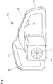
- FIG. 1 shows a preferred embodiment of a hand tool according to the invention.
- the hand-held tool 100 has a housing 10 for receiving a drive 14, which can be designed, for example, as an internal combustion engine or electric motor and can be seen in the figure by the fan blade indicated.
- a rear handle 11 Integrated in the housing 10 is a rear handle 11, which is usually gripped with the right hand in the embodiment shown.
- a button-shaped switching element 13 Arranged within the rear handle 11 is a button-shaped switching element 13, which is actuated with a finger of the right handle hand and by means of which the drive 14 can basically be switched on in the manner of a main switch.
- a first fuse element 15 in the form of a linear sensor.
- the securing member 15 protrudes along its axis with a part from the handle body and is forced in when the handle 11 is gripped by the handle hand. Due to the internal structure of the sensor, which will be explained in more detail later, an electrical contact is closed in the sensor by being pressed in and is evaluated as a safety signal by the safety electronics, not shown here.
- a further handle 12 in the form of a handle is arranged in front of the housing, which must be gripped by the left hand in two-hand operation.
- a second securing element 16 is embedded on the outside, which is constructed as a linear sensor in the same way as the first securing element 15.
- the arrangement of the two securing elements 15 and 16 ensures that, with suitable interaction with the switching element, that the handheld device 100 can only be put into operation as intended if the two handles 11, 12 are gripped by one hand at a time.
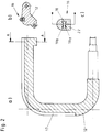
- the arrangement and internal structure of the securing member 16 in the handle of the handle 12 can be explained in more detail with reference to FIG. 2.
- FIG. 2a shows a longitudinal section of the handle 12 from FIG. 1.
- the handle can be made of solid material or a with plastic-filled metal pipe or the like. be made.
- a groove 17 is embedded over the largest part of the encompassable length, which - as the cross section along the area AA in FIG. 2b shows - accommodates the sensor-like securing element 16.
- the linear sensor preferably consists of a hose-like plastic channel 22 made of a non-conductive elastomer, in the cavity 18 of which two electrical contact conductors 19a, b are located opposite one another and not touching, parallel to one another run.
- the contact conductors 19a, b can consist, for example, of an electrically conductive elastomer or of a metal or other conductive layer applied to the surface.
- the two contact conductors 19a, b come into contact with one another, so that the sensor line which can be connected to the logic by corresponding connections is closed and a signal is generated which is fed as a control signal to the logic circuit.
- a film-like strip instead of the tube-like channel, which strip also closes a contact when pressure is applied, stretched or bent, or changes a resistance in such a way that a switching signal is generated.
- a closed elastic hose to be used, the volume of which is connected to an electrical pressure sensor.
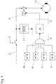
- the fuse elements 15 and 16 from FIG. 1 are connected to a fuse and logic circuit, the basic structure of which is shown in FIG. 3 in the case of a manual power tool that is electrically powered from the network:
- the drive comprises an electric motor 25 which can be connected to a power line 21 via a central motor control unit 24 (for example a relay) (and the switching element 13 designed as a button).
- the ditto 24 is controlled by a control logic 20, which is supplied from the network via a galvanically isolated power supply unit 23 and essentially contains an AND gate 27 at the input and a power unit 26 at the output.
- the power section 26 is designed, for example, as a circuit breaker and controls the current through the motor control unit 24.
- the AND gate 27 has a large number of inputs, as required, via which switching and fuse signals from various switching and fuse elements can be logically linked , so that the same 24 works only when all inputs of the AND gate 27 simultaneously assume the same logical state (1 or 0).
- Additional signal transmitters can be an overload switch 28 and - in the case of a chainsaw be in contact with the chain brake.
- the overload switch 28 can be designed, for example, as a thermal switch which protects the electric motor 25 against thermal overload.
- the contact 29 of the chain brake is closed when the chain brake is released.
- FIG. 4 A circuit structure of a circuit according to FIG. 3 which has been tried and tested in practice is shown in FIG. 4:
- the securing members 15 and 16 are designed in the form described above as hose resistors which, depending on the location of the actuation, have a resistance R2 or R3 between a few 100 to approximately 600 ohms at a maximum total hose length of 300 mm, for example.
- Via the switching element 13, a circuit breaker, the power supply of the electric saw (or the like) is switched on.
- the transformer 30 transforms the mains voltage when the transformer is loaded from the mains voltage to a low-voltage value that can be used for the electronic components.
- a bridge rectifier 31 converts the step-down AC voltage into a pulsating DC voltage.
- the two fuse elements 15 and 16 and possibly further switching elements 28, 29 are in series with a series resistor R1 and, together with a further resistor, form a voltage divider to which a transistor 33 is connected with its base.
- a transistor base current flows so that the transistor 33 in the collector-emitter path becomes conductive and a collector current can flow, whereby a motor relay 24 picks up and closes the load circuit and sets the electric motor in motion.
- the switching contacts 15, 16, 28 and 29 connected in series embody an elementary form of the AND gate in the circuit from FIG.
- the transistor 33 represents a power section which controls the motor relay 24.
- the simple circuit structure with proven components results in a robust and safely functioning circuit that can easily be extended to other signal contacts.
- suitable integrated circuits can also be used instead of the discrete components.
- the invention results in an externally powered hand-held device with a safety circuit, which is simple in construction, easy and safe to use and can be flexibly adapted to different applications.
Landscapes
- Life Sciences & Earth Sciences (AREA)
- Engineering & Computer Science (AREA)
- Forests & Forestry (AREA)
- General Engineering & Computer Science (AREA)
- Mechanical Engineering (AREA)
- Biodiversity & Conservation Biology (AREA)
- Ecology (AREA)
- Environmental Sciences (AREA)
- Wood Science & Technology (AREA)
- Auxiliary Devices For Machine Tools (AREA)
- Manipulator (AREA)
- Portable Power Tools In General (AREA)
Applications Claiming Priority (2)
| Application Number | Priority Date | Filing Date | Title |
|---|---|---|---|
| DE9308698U | 1993-06-11 | ||
| DE19939308698 DE9308698U1 (de) | 1993-06-11 | 1993-06-11 | Handarbeitsgerät mit einem Antrieb |
Publications (1)
| Publication Number | Publication Date |
|---|---|
| EP0628762A1 true EP0628762A1 (fr) | 1994-12-14 |
Family
ID=6894284
Family Applications (1)
| Application Number | Title | Priority Date | Filing Date |
|---|---|---|---|
| EP94108915A Withdrawn EP0628762A1 (fr) | 1993-06-11 | 1994-06-10 | Moyen d'entraînement pour outil à main |
Country Status (3)
| Country | Link |
|---|---|
| EP (1) | EP0628762A1 (fr) |
| JP (1) | JPH0747504A (fr) |
| DE (1) | DE9308698U1 (fr) |
Cited By (9)
| Publication number | Priority date | Publication date | Assignee | Title |
|---|---|---|---|---|
| DE19622594A1 (de) * | 1996-06-05 | 1997-12-11 | Gardena Kress & Kastner Gmbh | Motorisch betriebenes Handgerät |
| DE19634552A1 (de) * | 1996-08-27 | 1998-03-05 | Metabowerke Kg | Heckenschere |
| WO2004073005A1 (fr) * | 2003-02-13 | 2004-08-26 | C. & E. Fein Gmbh | Outil electrique |
| WO2010064937A1 (fr) * | 2008-12-04 | 2010-06-10 | Fairbrother Industries Limited | Commande d'enfonce-pieu |
| WO2012013274A1 (fr) * | 2010-07-27 | 2012-02-02 | Wacker Neuson Produktion GmbH & Co. KG | Outil de travail guidé à la main comportant un dispositif d'identification d'opérateur |
| EP2305439B1 (fr) | 2009-10-05 | 2019-12-18 | Makita Corporation | Outil électrique |
| USD887806S1 (en) | 2018-04-03 | 2020-06-23 | Milwaukee Electric Tool Corporation | Jigsaw |
| US10835972B2 (en) | 2018-03-16 | 2020-11-17 | Milwaukee Electric Tool Corporation | Blade clamp for power tool |
| US11014176B2 (en) | 2018-04-03 | 2021-05-25 | Milwaukee Electric Tool Corporation | Jigsaw |
Families Citing this family (9)
| Publication number | Priority date | Publication date | Assignee | Title |
|---|---|---|---|---|
| DE19522970A1 (de) * | 1995-06-28 | 1997-01-02 | Bosch Gmbh Robert | Heckenschere |
| DE19617882B4 (de) * | 1996-05-04 | 2005-08-11 | Metabowerke Gmbh | Elektromotorische Heckenschere mit Zweihandbedienung |
| DE10205951A1 (de) * | 2002-02-13 | 2003-08-21 | Cimosys Ag Goldingen | Steuerungsanordnung für mit elektrischer Niederspannung betriebene, mit Netzfreischaltung versehene netzabhängig gespeiste Geräte |
| DE102004024035A1 (de) * | 2004-05-11 | 2005-12-08 | Schmid & Wezel Gmbh & Co | Griff für ein motorangetriebenes Handwerkzeug |
| DE102007043035A1 (de) | 2007-09-11 | 2009-03-12 | Tool Express-Service Schraubertechnik Gmbh | Handwerkzeug mit Zwei-Hand-Bedienung |
| EP3031315B1 (fr) | 2014-12-09 | 2021-09-01 | Robert Bosch GmbH | Dispositif de poignée pour outils de jardinage |
| JP6905008B2 (ja) * | 2015-07-13 | 2021-07-21 | 株式会社マキタ | 制御方法および制御装置 |
| JP6556536B2 (ja) * | 2015-07-13 | 2019-08-07 | 株式会社マキタ | チェーンソー |
| DE102018251705A1 (de) * | 2018-12-27 | 2020-07-02 | Robert Bosch Gmbh | Handwerkzeugmaschine |
Citations (5)
| Publication number | Priority date | Publication date | Assignee | Title |
|---|---|---|---|---|
| US3662227A (en) * | 1969-02-13 | 1972-05-09 | Cableform Ltd | Control systems |
| EP0048019A2 (fr) * | 1980-09-15 | 1982-03-24 | Black & Decker Inc. | Dispositif de sécurité pour des outils à main ou des outils |
| EP0052185A2 (fr) * | 1980-11-15 | 1982-05-26 | Robert Bosch Gmbh | Dispositif électronique de protection des deux mains pour outils |
| FR2526126A1 (fr) * | 1982-05-03 | 1983-11-04 | Stihl Andreas | Dispositif de securite pour un appareil a moteur guide a la main |
| EP0544483A1 (fr) * | 1991-11-28 | 1993-06-02 | Black & Decker Inc. | Outil électrique avec détecteur de contact |
-
1993
- 1993-06-11 DE DE19939308698 patent/DE9308698U1/de not_active Expired - Lifetime
-
1994
- 1994-06-10 EP EP94108915A patent/EP0628762A1/fr not_active Withdrawn
- 1994-06-13 JP JP13023894A patent/JPH0747504A/ja active Pending
Patent Citations (5)
| Publication number | Priority date | Publication date | Assignee | Title |
|---|---|---|---|---|
| US3662227A (en) * | 1969-02-13 | 1972-05-09 | Cableform Ltd | Control systems |
| EP0048019A2 (fr) * | 1980-09-15 | 1982-03-24 | Black & Decker Inc. | Dispositif de sécurité pour des outils à main ou des outils |
| EP0052185A2 (fr) * | 1980-11-15 | 1982-05-26 | Robert Bosch Gmbh | Dispositif électronique de protection des deux mains pour outils |
| FR2526126A1 (fr) * | 1982-05-03 | 1983-11-04 | Stihl Andreas | Dispositif de securite pour un appareil a moteur guide a la main |
| EP0544483A1 (fr) * | 1991-11-28 | 1993-06-02 | Black & Decker Inc. | Outil électrique avec détecteur de contact |
Cited By (14)
| Publication number | Priority date | Publication date | Assignee | Title |
|---|---|---|---|---|
| EP0811315A3 (fr) * | 1996-06-05 | 1998-08-26 | GARDENA Kress + Kastner GmbH | Outil à main actionné par moteur |
| DE19622594A1 (de) * | 1996-06-05 | 1997-12-11 | Gardena Kress & Kastner Gmbh | Motorisch betriebenes Handgerät |
| DE19634552A1 (de) * | 1996-08-27 | 1998-03-05 | Metabowerke Kg | Heckenschere |
| WO2004073005A1 (fr) * | 2003-02-13 | 2004-08-26 | C. & E. Fein Gmbh | Outil electrique |
| US7507925B2 (en) | 2003-02-13 | 2009-03-24 | C. & E. Fein Gmbh | Power tool |
| WO2010064937A1 (fr) * | 2008-12-04 | 2010-06-10 | Fairbrother Industries Limited | Commande d'enfonce-pieu |
| AU2009323084B2 (en) * | 2008-12-04 | 2016-07-21 | Fairbrother Industries Limited | Post driver control |
| EP2305439B2 (fr) † | 2009-10-05 | 2024-11-27 | Makita Corporation | Outil électrique |
| EP2305439B1 (fr) | 2009-10-05 | 2019-12-18 | Makita Corporation | Outil électrique |
| WO2012013274A1 (fr) * | 2010-07-27 | 2012-02-02 | Wacker Neuson Produktion GmbH & Co. KG | Outil de travail guidé à la main comportant un dispositif d'identification d'opérateur |
| US10835972B2 (en) | 2018-03-16 | 2020-11-17 | Milwaukee Electric Tool Corporation | Blade clamp for power tool |
| US11014176B2 (en) | 2018-04-03 | 2021-05-25 | Milwaukee Electric Tool Corporation | Jigsaw |
| US11813682B2 (en) | 2018-04-03 | 2023-11-14 | Milwaukee Electric Tool Corporation | Jigsaw |
| USD887806S1 (en) | 2018-04-03 | 2020-06-23 | Milwaukee Electric Tool Corporation | Jigsaw |
Also Published As
| Publication number | Publication date |
|---|---|
| DE9308698U1 (de) | 1994-10-27 |
| JPH0747504A (ja) | 1995-02-21 |
Similar Documents
| Publication | Publication Date | Title |
|---|---|---|
| EP0628762A1 (fr) | Moyen d'entraînement pour outil à main | |
| EP1873800B1 (fr) | Machine-outil électrique et interrupteur correspondant | |
| DE3216446C2 (fr) | ||
| DE69203048T2 (de) | Verbesserungen bei elektrischen Einrichtungen bei Leistungswerkzeugen und Schaltern. | |
| DE2039862B2 (de) | Automatisch wirkende Aerosolabgabevorrichtung | |
| DE19732888A1 (de) | Bedienvorrichtung für ein Flurförderzeug | |
| DE102007043035A1 (de) | Handwerkzeug mit Zwei-Hand-Bedienung | |
| DE2809747A1 (de) | Doppelpoliger schalter, insbesondere fuer motorbetriebene werkzeuge, wie elektrische bohrer | |
| EP1593136A1 (fr) | Outil electrique | |
| DE69127244T2 (de) | Schalter mit veränderlichem Widerstand | |
| DE2824510C2 (de) | Vorrichtung zum Steuern der Bewegung eines angetriebenen Tores | |
| DE102017125055A1 (de) | Variabler Drehzahlregler zur Verwendung mit einer elektrischen Vorrichtung | |
| EP1081725A2 (fr) | Interrupteur marche-arrêt et dispositif pour la régulation de vitesse d'un outil électrique | |
| DE2929047B2 (de) | Druckempfindlicher Schalter mit Piktogramm | |
| DE102019201516A1 (de) | Roboter mit wenigstens einer Abdeckung und wenigstens einem Kontaktsensor | |
| EP0817226A2 (fr) | Interrupteur à bascule | |
| DE3324545A1 (de) | Elektromotorisch betriebenes handgeraet | |
| DE69306977T2 (de) | Mechanische Vorrichtung mit veränderlicher resistiver Schaltung zur Steuerung einer Last, insbesondere eines Elektromotors | |
| DE19621192A1 (de) | Niederspannungsschaltgerät | |
| EP0085730B1 (fr) | Commutateur à pression bipolaire avec dispositif électronique de commande et de réglage destiné à étre monté dans un appareil électrique actionné à la main | |
| DE3414211C2 (fr) | ||
| EP1595661B1 (fr) | Poignée avec dispositif de sécurité pour outil à main motorisé | |
| DE102009012715A1 (de) | Elektrischer Schalter | |
| EP1929494B1 (fr) | Interrupteur electrique | |
| DE69016215T2 (de) | Elektrische vorrichtung zum umschalten auf ersatzenergie. |
Legal Events
| Date | Code | Title | Description |
|---|---|---|---|
| PUAI | Public reference made under article 153(3) epc to a published international application that has entered the european phase |
Free format text: ORIGINAL CODE: 0009012 |
|
| AK | Designated contracting states |
Kind code of ref document: A1 Designated state(s): CH DE FR GB IT LI SE |
|
| STAA | Information on the status of an ep patent application or granted ep patent |
Free format text: STATUS: THE APPLICATION IS DEEMED TO BE WITHDRAWN |
|
| 18D | Application deemed to be withdrawn |
Effective date: 19950615 |