EP0628893A2 - Appareil de formation d'images utilisant une méthode de transfert sans contact - Google Patents
Appareil de formation d'images utilisant une méthode de transfert sans contact Download PDFInfo
- Publication number
- EP0628893A2 EP0628893A2 EP94108877A EP94108877A EP0628893A2 EP 0628893 A2 EP0628893 A2 EP 0628893A2 EP 94108877 A EP94108877 A EP 94108877A EP 94108877 A EP94108877 A EP 94108877A EP 0628893 A2 EP0628893 A2 EP 0628893A2
- Authority
- EP
- European Patent Office
- Prior art keywords
- transfer
- photoreceptor drum
- transfer sheet
- image
- sheet
- Prior art date
- Legal status (The legal status is an assumption and is not a legal conclusion. Google has not performed a legal analysis and makes no representation as to the accuracy of the status listed.)
- Withdrawn
Links
Images


Classifications
-
- G—PHYSICS
- G03—PHOTOGRAPHY; CINEMATOGRAPHY; ANALOGOUS TECHNIQUES USING WAVES OTHER THAN OPTICAL WAVES; ELECTROGRAPHY; HOLOGRAPHY
- G03G—ELECTROGRAPHY; ELECTROPHOTOGRAPHY; MAGNETOGRAPHY
- G03G15/00—Apparatus for electrographic processes using a charge pattern
- G03G15/14—Apparatus for electrographic processes using a charge pattern for transferring a pattern to a second base
- G03G15/16—Apparatus for electrographic processes using a charge pattern for transferring a pattern to a second base of a toner pattern, e.g. a powder pattern, e.g. magnetic transfer
- G03G15/163—Apparatus for electrographic processes using a charge pattern for transferring a pattern to a second base of a toner pattern, e.g. a powder pattern, e.g. magnetic transfer using the force produced by an electrostatic transfer field formed between the second base and the electrographic recording member, e.g. transfer through an air gap
Definitions
- the present invention relates to a transfer arrangement, and more specifically, to a transfer arrangement incorporated in an image forming apparatus such as an electrographic copying machine, a printer and a facsimile machine for electrostatically transferring a toner image formed on the surface of an electrostatic latent image carrier incorporated in the apparatus onto a sheet of paper such as a transfer sheet by means of a transfer roller.
- an image forming apparatus such as an electrographic copying machine, a printer and a facsimile machine for electrostatically transferring a toner image formed on the surface of an electrostatic latent image carrier incorporated in the apparatus onto a sheet of paper such as a transfer sheet by means of a transfer roller.
- a non-contact-type corona transfer method using a corona discharger as a means for supplying a charge to the electrostatic latent image carrier a contact-type bias roller transfer method using a conductive roller as the charge supplying means.
- a transfer arrangement employing the corona transfer method includes a corona discharger.
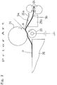
- a corona discharger 22 is arranged so that a necessary gap is left between the corona discharger 22 and a photoreceptor drum 21 used as the electrostatic latent image carrier.
- the corona discharger 22 charges a transfer sheet P conveyed through the gap between the rotary photoreceptor drum 21 and the corona discharger 22 by applying a corona charge of a polarity reverse to that of toner from the reverse side of the transfer sheet P.
- the transfer sheet P is made to partly adhere to the surface of the photoreceptor drum 21, and the charged toner on the surface of the photoreceptor drum 21 is transferred onto the transfer sheet P by a Coulomb force.
- a transfer arrangement employing the bias roller transfer method includes a transfer roller made of urethane resin provided with conductivity by being mixed with a carbon or alkali metal.
- a transfer roller 23 is arranged to be rotatively in contact with the photoreceptor drum 21.
- the transfer roller 23 presses the transfer sheet P passing between the peripheries of the photoreceptor drum 21 and the transfer roller 23 against the toner adhering to the surface of the photoreceptor drum 21, and transfers the toner image on the surface of the photoreceptor drum 21 onto the transfer sheet P by a transfer voltage of a polarity reverse to that of the toner applied to the axial core of the transfer roller 23.
- the transfer arrangement of this method which uses very weak current, is advantageous since the generation of discharge products such as ozone and NOx is considerably small compared to the transfer arrangement of the corona discharge method (1/20 to 1/30 of that of existing arrangements of the corona discharge method) and since no means is necessary for separating the transfer sheet P.
- the transfer sheet P is pressed against the surface of the photoreceptor drum 21 by the surface of the transfer roller 23. For this reason, it is apt to occur that the toner located at a central portion of the surface of the photoreceptor drum 21 is not transferred to the transfer sheet P and that toner scatters and adheres to a peripheral portion of the image transferred onto the transfer sheet P.
- reference numeral 24 represents a pair of resist rollers for conveying the transfer sheet P
- reference designations 25a and 25b represent guide members for guiding the transfer sheet P to the surface of the photoreceptor drum 21
- reference numeral 26 represents a supporting table for guiding the transfer sheet P onto which the image has been transferred to a fixing roller pair (not shown).
- the resist rollers 24 send out the transfer sheet P at a speed equal to the peripheral speed of the surface of the photoreceptor drum 21 in accordance with the rotation of the photoreceptor drum 21, so that the transfer sheet P is guided toward the photoreceptor drum along the guide members 25a and 25b.
- the transfer sheet P moves at a speed equal to the peripheral speed of the surface of the photoreceptor drum 21 while being in contact with the surface of the photoreceptor drum 21.
- the toner image on the surface of the photoreceptor drum 21 is transferred at this time.
- the transfer sheet P After being separated from the surface of the photoreceptor drum 21 and reaching the upper surface of the supporting table 26, the transfer sheet P is released from the resist rollers 24, and thereafter, it is conveyed along the upper surface of the supporting table 26 in accordance with the rotation of the photoreceptor drum 21. Between just in front of the position at which the transfer sheet P abuts the surface of the photoreceptor drum 21, and the supporting table 26, the transfer sheet P has a tendency to bend in a direction opposite to the curve of the surface of the photoreceptor drum 21. The resiliency of the transfer sheet P generated by the bend works as a pressing force on a portion of the transfer sheet P which is in contact with the surface of the photoreceptor drum 21.
- the conveying speed of the transfer sheet P and the angles of guide surfaces Sa and Sb of the guide members 25a and 25b are set so that the transfer sheet P is in close contact with the surface of the photoreceptor drum 21 while rotating at a speed equal to the speed of the drum 21.
- the guide members 25a and 25b are arranged to be close to the photoreceptor drum 21.
- angles of the guide surfaces Sa and Sb of the guide members 25a and 25b are adjusted so that an angle ⁇ of the transfer sheet P to a tangential plane (shown by the alternate long and short dash line in Fig. 3) at the position where the front end of the transfer sheet P abuts the surface of the photoreceptor drum 21 is large to thereby press the transfer sheet P against the surface of the photoreceptor drum 21 so as to be in close contact therewith and out of contact with the transfer roller 23.
- the transfer roller 23 since the transfer roller 23 is out of contact with the transfer sheet P, gravity works on the transfer sheet P in a direction to separate the transfer sheet P from the photoreceptor drum 21 due to the dead load of the transfer sheet P. As a result, the transfer sheet P and the photoreceptor drum 21 may not be in contact at a sufficient contact pressure. When the transfer sheet P and the photoreceptor drum 21 are not in contact at a sufficient contact pressure, mal-transfer occurs or the transfer sheet P comes in contact with the transfer roller 23 so that dirt on the transfer roller 23 adheres to the transfer sheet P.
- An object of the present invention is to provide a transfer arrangement of a type where the transfer roller is arranged so that a gap larger than the thickness of the transfer sheet is left between the transfer roller and the electrostatic latent image carrier, wherein the transfer sheet is in contact with the electrostatic latent image carrier at a sufficient contact pressure without any need to bend the transfer sheet by a guide member.
- the transfer roller is arranged above the electrostatic latent image carrier so that the transfer of the image onto the transfer sheet is performed above the electrostatic latent image carrier.
- the transfer roller since the transfer roller is arranged above the electrostatic latent image carrier, the transfer sheet conveyed to the gap between the transfer roller and the electrostatic latent image carrier comes into close contact with the surface of the electrostatic latent image carrier due to its own dead load. Therefore, since it is unnecessary to bend the transfer sheet by a guide member so as to be pressed against the surface of the electrostatic latent image carrier, the movement of the transfer sheet is never resisted by the guide member, and the conveying speed of the transfer sheet receives no influence when the transfer sheet is released from the resist rollers provided in the upstream side of the electrostatic latent image carrier.
- Fig. 4 shows a transfer arrangement of the present invention employed in a digital electrographic copying machine.
- reference numeral 10 represents a photoreceptor drum (electrostatic latent image carrier) which comprises a tube made of a metal such as aluminum on which a photosensitive layer made of amorphous silicon (a-Si) or other photosensitive material is formed.
- the photoreceptor drum 10 is arranged substantially horizontally in a copying machine 11, and is rotated counterclockwise (i.e. in the direction of arrow A) by a driving system (not shown) provided in the copying machine 11.
- the direction of rotation of the photoreceptor drum 10 is set to correspond to the conveying direction of a transfer sheet P like the clockwise (in the direction of arrow B) rotation of a subsequently-described transfer roller 1.
- a charging means 6, a developing means 4, a non-contact-type transfer roller 1 and a charge-removing and cleaning means 7 are arranged in this order in the rotation direction of the photoreceptor drum 10. Between the surface of the photoreceptor drum 10 and the surface of the transfer roller 1, there exists a gap larger than the thickness of a transfer sheet which passes therethrough. Below the charging means 6, an exposure means 5 is arranged. Between the charging means 6 and the developing means 4, the photoreceptor drum 10 is exposed to a laser beam L from the exposure means 5.
- the photosensitive layer on the surface of the photoreceptor drum 10 is charged by corona discharge by the charging means 6.
- the exposure means 5 irradiates the laser beam L in accordance with an image read out from an original (not shown) to the charged surface of the photoreceptor drum 10, thereby forming an electrostatic latent image.
- the electrostatic latent image is formed into a toner image by being toner-developed by the developing means 4.
- the transfer sheet P is supplied, in accordance with the rotation of photoreceptor drum 10 (arrow A), from a paper feeding cassette 9 by a paper feeding roller 3, and conveyed along a sheet conveying path constituted by an upper guide member 15a and a lower guide member 15b arranged to be opposite to each other.
- a pair of resist rollers 2 send the transfer sheet P into the gap between the photoreceptor drum 10 and the transfer roller 1, at a speed equal to the peripheral speed of the photoreceptor drum 10. While the transfer sheet P conveyed in this manner is in contact with the surface of the photoreceptor drum 10, a voltage of a polarity reverse to that of the toner image on the surface of the photoreceptor drum 10 is applied to the transfer roller 1.
- the Coulomb's force generated by this voltage application By the Coulomb's force generated by this voltage application, the charged toner adhering to the surface of the photoreceptor drum 10 is transferred onto the surface of the transfer sheet P. Since the transfer sheet P is in contact with the photoreceptor drum 10 at a stable contact pressure, the generation of uneven portions in the transferred image is prevented.
- the transfer sheet P to which the toner image has been transferred is separated from the surface of the photoreceptor drum 10, and heated and pressurized while passing between the rollers at a fixing means 8, so that the toner image is fixed onto the transfer sheet P.
- the transfer sheet P is conveyed by both the fixing means 8 and the resist rollers 2.
- the rear end of the transfer sheet P is released from the resist rollers 2 and discharged onto a tray 13 in accordance with the rotations of the photoreceptor drum 10 and the rollers constituting the fixing means 8.
- the toner image has been transferred on the undersurface of the transfer sheet P when it is advancing toward the fixing means 8 after separated from the photoreceptor drum 10.
- the undersurface of the transfer sheet P on which the toner image has been transferred never abuts a guide member 16. Therefore, the toner image which has not been fixed yet is not damaged.
- the residual toner and charge on the surface of the photoreceptor drum 10 are removed by the charge-removing and cleaning means 7.
- the photoreceptor drum 10 is ready for the next charging when it makes one revolution after the last charging.
- Fig. 5 shows a positional relationship between the transfer roller 1 and the photoreceptor drum 10.
- the transfer roller 1 is arranged parallel to the axis (not shown) of the photoreceptor drum 10, and a distance d which is greater than the thickness of the transfer sheet P (Fig. 4) is left between the transfer roller 1 and the surface of the photoreceptor drum 10.
- the transfer roller 1 includes a body 1a made of a conductive rubber, a rotational axis 1b made of a metal, and a roller 1c made of an insulating material.
- the body 1a has a length equal to or greater than the width of a toner image forming area 10A on the surface of the photoreceptor drum 10, and is formed to be of a long-axis roller shape around the rotational axis 1b.
- the body 1a preferably has a volume electrical resistivity ⁇ v of 106 to 107 ⁇ cm.
- a conductive resin material such as polystyrene or urethane resin in which carbon or an alkali metal is mixed and a conductive rubber material are suitable for this purpose.
- the body 1a and the rotational axis 1b are connected electrically.
- a voltage of a polarity reverse to that of the charged toner adhering to the surface of the photoreceptor drum 10 is applied to the rotational axis 1b from a power source 12 through a contact terminal (not shown).
- the transfer sheet P is charged as described previously, so that the charged toner adhering to the surface of the photoreceptor drum 10 is transferred onto the transfer sheet P.
- the roller 1c made of an insulating resin is provided to regulate the distance d between the surface of the photoreceptor drum 10 and the transfer roller 1.
- the roller 1c is in contact with the surface of the photoreceptor drum 10 outside the toner image forming area 10A on the surface of the photoreceptor drum 10. While the distance d is set at 0.5mm in this embodiment, it can be varied by employing a pair of rollers having another diameter.
- the distance d may be changed to any value as far as it is greater than the thickness of the transfer sheet P. It may be set to the same value as that of the arrangement as shown in Fig. 3 where the transfer roller 23 is arranged below the photoreceptor drum 21. However, when the transfer roller 1 is arranged above the photoreceptor drum 10 as shown in Figs. 4 and 5, the distance d can be set shorter than in the arrangement of Fig. 3 since the transfer sheet P comes into close contact with the photoreceptor drum 10 due to its own dead load.
- the transfer roller 1 is arranged so that the distance d between the transfer roller 1 and the photoreceptor drum 10 is greater than the thickness of the transfer sheet P, the transfer sheet P never comes in contact with the surface of the transfer roller 1 when it is in contact with the surface of the photoreceptor drum 10 due to its own dead load as described above. As a result, dirt on the transfer roller 1 never adheres to the transfer sheet P.
- the transfer sheet P is not in contact with the photoreceptor drum 21 at a sufficient contact pressure according to the gravity working on the transfer sheet P.
- the degree of insufficiency of the contact pressure differs according to the quality and thickness of the transfer sheet P. When the contact pressure is insufficient, mal-transfer occurs.
- the guide members 25a and 25b are required whose angles are adjusted to bend the transfer sheet P.
- no guide members are necessary to bend the transfer sheet P. That is, when the transfer roller 1 is located above the photoreceptor drum 10 as described previously, gravity works on the transfer sheet P in a direction to bring the transfer sheet P into close contact with the photoreceptor drum 10, and therefore, the transfer sheet P is brought into close contact with the photoreceptor drum 10 without any need of guide members the angles of which are adjusted.
- the angles of the guide members 15a and 15b are not adjusted to bring the transfer sheet P into close contact.
- the guide members 25a and 25b in the prior art are provided not only to constitute the conveying path for the transfer sheet P but also to guide the transfer sheet P to approach the photoreceptor drum 21 while rising at an angle to thereby prevent the contact of the transfer sheet P with the transfer roller 23, and to guide the front end of the transfer sheet P to a predetermined position to be in close contact with the surface of the photoreceptor drum 21.
- the guide members 15a and 15b are provided merely to constitute the conveying path for the transfer sheet P.
- the transfer roller 1 when the transfer roller 1 is arranged above the photoreceptor drum 10, since the transfer sheet P conveyed into the gap between the transfer roller 1 and the photoreceptor drum 10 comes in close contact with the surface of the photoreceptor drum 10 due to its own dead load, it is unnecessary to press the transfer sheet P against the surface of the photoreceptor drum 10 by bending it by use of the guide members. Therefore, it is unnecessary to provide the guide members which resist the movement of the transfer sheet P. For example, the movement of the transfer sheet P receives no influence when the transfer sheet P is released from the resist rollers 2 arranged in the upstream side of the photoreceptor drum 10. That is, the problem no longer exists that a slight positional shift is caused in the transferred image at this time of release. Moreover, since the friction is little between the transfer sheet P and the guide members 15a and 15b, paper dust, which causes mal-transfer and troubles in the image forming apparatus, is hardly raised.
- a rotary photoreceptor drum is used as an electrostatic latent image carrier in Fig. 4, the present invention may be employed for an arrangement where an endless-belt-type photoreceptor which circularly moves is used.
- a member which is fixed at a position opposite to the photoreceptor drum 10 may be used instead of a rotary transfer roller.
- the transfer arrangement of the present invention is not easy to employ in an analog plain paper copier (PPC) where the reading of the original image and the exposure to the photoreceptor drum 10 are performed by use of the same light.
- PPC plain paper copier
- the transfer roller 1 is arranged above the photoreceptor drum 10
- the exposure means 5 serving as a light source above the photoreceptor drum 10.
- the digital PPC as shown in Fig. 4
- the present invention is readily employed since different light beams are used for the reading of the original and for the exposure.
- the present invention is suitable for use in an apparatus such as a facsimile apparatus, a printer and a digital PPC where a laser optical system or a light emitting diode (LED) optical system is used as the exposure means.
- LED light emitting diode
Landscapes
- Physics & Mathematics (AREA)
- General Physics & Mathematics (AREA)
- Electrostatic Charge, Transfer And Separation In Electrography (AREA)
Applications Claiming Priority (2)
| Application Number | Priority Date | Filing Date | Title |
|---|---|---|---|
| JP138429/93 | 1993-06-10 | ||
| JP5138429A JP2978367B2 (ja) | 1993-06-10 | 1993-06-10 | 転写装置 |
Publications (2)
| Publication Number | Publication Date |
|---|---|
| EP0628893A2 true EP0628893A2 (fr) | 1994-12-14 |
| EP0628893A3 EP0628893A3 (fr) | 1996-09-11 |
Family
ID=15221768
Family Applications (1)
| Application Number | Title | Priority Date | Filing Date |
|---|---|---|---|
| EP94108877A Withdrawn EP0628893A3 (fr) | 1993-06-10 | 1994-06-09 | Appareil de formation d'images utilisant une méthode de transfert sans contact. |
Country Status (2)
| Country | Link |
|---|---|
| EP (1) | EP0628893A3 (fr) |
| JP (1) | JP2978367B2 (fr) |
Families Citing this family (2)
| Publication number | Priority date | Publication date | Assignee | Title |
|---|---|---|---|---|
| JP2009211019A (ja) | 2007-07-10 | 2009-09-17 | Ricoh Co Ltd | 画像形成装置及び画像形成方法 |
| US8270885B2 (en) | 2007-07-10 | 2012-09-18 | Ricoh Company, Limited | Image forming apparatus utilizing plural pressers of different weights and image forming method forming an image with the image forming apparatus |
Family Cites Families (4)
| Publication number | Priority date | Publication date | Assignee | Title |
|---|---|---|---|---|
| JPS63210877A (ja) * | 1987-02-27 | 1988-09-01 | Toshiba Corp | 画像形成装置 |
| JP2883159B2 (ja) * | 1990-05-11 | 1999-04-19 | 日本電信電話株式会社 | 像形成装置 |
| JPH04140775A (ja) * | 1990-10-02 | 1992-05-14 | Fujitsu Ltd | 静電記録装置 |
| JPH04153682A (ja) * | 1990-10-17 | 1992-05-27 | Murata Mach Ltd | 転写装置 |
-
1993
- 1993-06-10 JP JP5138429A patent/JP2978367B2/ja not_active Expired - Lifetime
-
1994
- 1994-06-09 EP EP94108877A patent/EP0628893A3/fr not_active Withdrawn
Also Published As
| Publication number | Publication date |
|---|---|
| EP0628893A3 (fr) | 1996-09-11 |
| JP2978367B2 (ja) | 1999-11-15 |
| JPH06348151A (ja) | 1994-12-22 |
Similar Documents
| Publication | Publication Date | Title |
|---|---|---|
| KR930003617B1 (ko) | 영상형성장치 | |
| JP4175395B2 (ja) | 画像形成装置 | |
| US4750018A (en) | Pre-transfer copy sheet cleaning apparatus | |
| EP0603581B1 (fr) | Dispositif de transfert | |
| US5617193A (en) | Image transferred sheet conveying guide for use in an image forming apparatus | |
| US6701119B2 (en) | Image forming apparatus including opposed insulating and conducting transfer material guide members to prevent null transfer | |
| US5926682A (en) | Image forming apparatus | |
| US6498913B1 (en) | Static charge controlling system and a reproduction machine having same | |
| US5918096A (en) | Image transfer apparatus | |
| EP0628893A2 (fr) | Appareil de formation d'images utilisant une méthode de transfert sans contact | |
| US7092659B2 (en) | Discharge methods and systems in electrophotography | |
| JP3364553B2 (ja) | 画像形成装置 | |
| GB2127230A (en) | Corona discharge device for separating recording paper from image retaining member | |
| JPH0569217B2 (fr) | ||
| US20070025772A1 (en) | Image-Forming Device | |
| JPH07261562A (ja) | 転写ベルト装置 | |
| JPH10282798A (ja) | 画像形成装置 | |
| JP3210093B2 (ja) | 画像形成装置 | |
| JPH03154086A (ja) | 画像形成装置の転写装置 | |
| JPH06149012A (ja) | ローラ帯電装置 | |
| JPH01280782A (ja) | 画像形成装置 | |
| JP3356248B2 (ja) | 画像形成装置 | |
| JP2535025Y2 (ja) | 記録紙搬送装置 | |
| EP0628886A1 (fr) | Séparateur de feuille de transfert pour un appareil de formation d'images | |
| JPH0540418A (ja) | 画像形成装置 |
Legal Events
| Date | Code | Title | Description |
|---|---|---|---|
| PUAI | Public reference made under article 153(3) epc to a published international application that has entered the european phase |
Free format text: ORIGINAL CODE: 0009012 |
|
| AK | Designated contracting states |
Kind code of ref document: A2 Designated state(s): DE FR GB IT |
|
| PUAL | Search report despatched |
Free format text: ORIGINAL CODE: 0009013 |
|
| AK | Designated contracting states |
Kind code of ref document: A3 Designated state(s): DE FR GB IT |
|
| 17P | Request for examination filed |
Effective date: 19970228 |
|
| 17Q | First examination report despatched |
Effective date: 19970327 |
|
| STAA | Information on the status of an ep patent application or granted ep patent |
Free format text: STATUS: THE APPLICATION IS DEEMED TO BE WITHDRAWN |
|
| 18D | Application deemed to be withdrawn |
Effective date: 19970807 |