EP0629104A2 - Circuit pour limiter le courant continu decrête et/ou le courant d'appel par l'allumage d'une lampe à décharge - Google Patents
Circuit pour limiter le courant continu decrête et/ou le courant d'appel par l'allumage d'une lampe à décharge Download PDFInfo
- Publication number
- EP0629104A2 EP0629104A2 EP94107985A EP94107985A EP0629104A2 EP 0629104 A2 EP0629104 A2 EP 0629104A2 EP 94107985 A EP94107985 A EP 94107985A EP 94107985 A EP94107985 A EP 94107985A EP 0629104 A2 EP0629104 A2 EP 0629104A2
- Authority
- EP
- European Patent Office
- Prior art keywords
- current
- circuit arrangement
- arrangement according
- switch device
- state
- Prior art date
- Legal status (The legal status is an assumption and is not a legal conclusion. Google has not performed a legal analysis and makes no representation as to the accuracy of the status listed.)
- Granted
Links
- 238000010438 heat treatment Methods 0.000 claims description 14
- 239000007858 starting material Substances 0.000 description 9
- 230000002411 adverse Effects 0.000 description 1
- 239000003637 basic solution Substances 0.000 description 1
- 230000000694 effects Effects 0.000 description 1
Images

Classifications
-
- H—ELECTRICITY
- H05—ELECTRIC TECHNIQUES NOT OTHERWISE PROVIDED FOR
- H05B—ELECTRIC HEATING; ELECTRIC LIGHT SOURCES NOT OTHERWISE PROVIDED FOR; CIRCUIT ARRANGEMENTS FOR ELECTRIC LIGHT SOURCES, IN GENERAL
- H05B41/00—Circuit arrangements or apparatus for igniting or operating discharge lamps
- H05B41/14—Circuit arrangements
- H05B41/16—Circuit arrangements in which the lamp is fed by DC or by low-frequency AC, e.g. by 50 cycles/sec AC, or with network frequencies
- H05B41/18—Circuit arrangements in which the lamp is fed by DC or by low-frequency AC, e.g. by 50 cycles/sec AC, or with network frequencies having a starting switch
-
- H—ELECTRICITY
- H05—ELECTRIC TECHNIQUES NOT OTHERWISE PROVIDED FOR
- H05B—ELECTRIC HEATING; ELECTRIC LIGHT SOURCES NOT OTHERWISE PROVIDED FOR; CIRCUIT ARRANGEMENTS FOR ELECTRIC LIGHT SOURCES, IN GENERAL
- H05B41/00—Circuit arrangements or apparatus for igniting or operating discharge lamps
- H05B41/02—Details
- H05B41/04—Starting switches
- H05B41/042—Starting switches using semiconductor devices
- H05B41/044—Starting switches using semiconductor devices for lamp provided with pre-heating electrodes
Definitions
- the invention relates to a circuit arrangement for limiting the DC peak value and the starting alternating current after switching on a discharge lamp according to the preamble of claim 1.
- Ballasts for discharge lamps operated with alternating current generally contain a choke for current limitation.
- the discharge lamps act almost like rectifiers for the first time after ignition. This means that a relatively high direct current flows through the choke with a negligible superimposed alternating current component. In extreme cases, this has the consequence that the operating point of the throttle shifts into the saturation range.
- the choke which has only a very low DC resistance anyway, also represents a low AC resistance in this case. This in turn results in a very high DC peak value, which can adversely affect the life of the lamps.
- the case described above applies in particular to high-pressure discharge lamps.
- the invention has for its object to provide a circuit arrangement of the type described, which allows a choke to be used with smaller dimensions.
- the object is achieved according to the invention by a further current limiting circuit part connected in series with the inductor, which passes a more limited current in a first state after switching on the AC supply source and, after a certain time, switches to a second state in which it is less passes very limited current.
- the current limiting circuit part thus relieves the current limiting function of the choke in the switch-on phase, with the result that the latter can be dimensioned smaller.
- the switchover of the current limiting circuit part from one state to the second state can either be made use of in the switch-on phase on one of the components of the ballast or. Ignitor occurring heating or by a timing device. Refinements of the basic solution to the problem specified in claim 1 are given in subclaims 2 to 13.
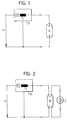
- a high-pressure discharge lamp HL is connected to an alternating current source U via an ignition device ZG.
- the igniter ZG contains a further current limiting part B connected in series with the latter.
- a current limiting circuit part B is connected in series with the choke, which not only limits the starting alternating current in the starting phase, but also the direct current peak value. After a certain period of time, within which the rectifying effect of the high-pressure discharge lamp subsides, the current limiting circuit part B then switches from the first state to a second state in which it limits the current flowing through less. Since the current now has a significantly lower DC component, the current is effectively limited in this case by the choke L.
- a low-pressure gas discharge lamp NL is connected to an alternating current source U via a ballast VG.
- An ignition starter Z is located parallel to the gas discharge lamp NL. After the ignition starter Z has been closed, a glow discharge occurs on it, as a result of which it heats up and closes. After the ignition starter Z has been closed, practically the full mains voltage U is at the ballast VG, since the heating filaments of the gas discharge lamp NL are still cold and have a low resistance. This leads to a high starting alternating current through the ballast VG.
- the ballast VG contains the usual choke L and a current limiting part B connected in series with the choke. The current limiting part B switches, as described in connection with FIG.
- the inductor L can therefore be dimensioned smaller than without a power supply circuit part B.
- the ignition starter Z cools down after closing and finally opens again, which in cooperation with the inductor L generates a high ignition pulse which is used to ignite the Gas discharge lamp NL leads. After ignition, the arrangement is in the operating state and a gas discharge current flows through the lamp. The ignition starter Z remains open after ignition, since no further glow discharge occurs on it.
- the current limiting circuit part consists of a series resistor RV and a temperature-sensitive switch S connected in parallel therewith.
- the switch S can be, for example, a bimetallic switch which is open in the cold state and closes when heated.
- the arrangement is chosen such that heat generated by the current flowing through it is transferred to the switch S in the series resistor RV.
- the inductor L can also be in thermal contact with the switch S.
- the current limiting part according to FIG. 4 also contains a series resistor RH, which is connected in series with the series resistor RV and in parallel with the inductor L.
- the series resistor RH is also in thermal contact with the switch S.
- the heating resistor RH is connected in parallel to the series circuit comprising the series resistor RV and the inductor L.
- the heating resistor RH serves the same purpose as that described in connection with FIG. 4.
- the current limiting circuit part B contains a control circuit ST for switching the switch from the first state to the second state.
- the switchover does not take place here due to heat development on one of the elements, but rather in that the control circuit triggers the switchover after a certain period of time.
- ohmic resistance RV can of course also be replaced by any equivalent impedance in the individual exemplary embodiments.
Landscapes
- Circuit Arrangements For Discharge Lamps (AREA)
- Emergency Protection Circuit Devices (AREA)
- Ignition Installations For Internal Combustion Engines (AREA)
Applications Claiming Priority (4)
| Application Number | Priority Date | Filing Date | Title |
|---|---|---|---|
| DE4319501 | 1993-06-11 | ||
| DE4319501 | 1993-06-11 | ||
| DE4404658A DE4404658A1 (de) | 1993-06-11 | 1994-02-14 | Schaltungsanordnung zur Begrenzung des Gleichstromscheitelwertes und/oder des Anlaufwechselstromes nach dem Einschalten einer Entladungslampe |
| DE4404658 | 1994-02-14 |
Publications (3)
| Publication Number | Publication Date |
|---|---|
| EP0629104A2 true EP0629104A2 (fr) | 1994-12-14 |
| EP0629104A3 EP0629104A3 (fr) | 1995-08-02 |
| EP0629104B1 EP0629104B1 (fr) | 1999-12-15 |
Family
ID=25926712
Family Applications (1)
| Application Number | Title | Priority Date | Filing Date |
|---|---|---|---|
| EP94107985A Expired - Lifetime EP0629104B1 (fr) | 1993-06-11 | 1994-05-24 | Circuit pour limiter le courant continu decrête et/ou le courant d'appel par l'allumage d'une lampe à décharge |
Country Status (3)
| Country | Link |
|---|---|
| EP (1) | EP0629104B1 (fr) |
| AT (1) | ATE187863T1 (fr) |
| DE (2) | DE4404658A1 (fr) |
Cited By (2)
| Publication number | Priority date | Publication date | Assignee | Title |
|---|---|---|---|---|
| AT12721U1 (de) * | 2011-04-22 | 2012-10-15 | Tridonic Gmbh & Co Kg | Vorrichtung zum betreiben einer hochdruckentladungslampe |
| DE102011055664A1 (de) | 2011-11-24 | 2013-05-29 | Vossloh-Schwabe Deutschland Gmbh | Spannungsversorgungseinrichtung |
Families Citing this family (1)
| Publication number | Priority date | Publication date | Assignee | Title |
|---|---|---|---|---|
| DE19515592A1 (de) * | 1995-05-02 | 1996-11-07 | Walter Holzer | Gasentladungslampe mit Schonstart |
Family Cites Families (8)
| Publication number | Priority date | Publication date | Assignee | Title |
|---|---|---|---|---|
| DE1589205C3 (de) * | 1967-09-19 | 1974-11-21 | Fritz Ennenda Glarus Knobel (Schweiz) | Schaltungsanordnung für den kapazitiven Betrieb von Niederspannungs-Leuchtstofflampen |
| DE2451786A1 (de) * | 1974-10-31 | 1976-05-06 | Bosch Gmbh Robert | Schaltung fuer leuchtstofflampen |
| US3996495A (en) * | 1975-07-25 | 1976-12-07 | North American Philips Corporation | High efficiency ballast system for electric discharge lamps |
| DE2710066A1 (de) * | 1977-03-08 | 1978-09-14 | Helmut Dipl Chem Ulrich | Leuchtstofflampen-startschaltung und -speiseschaltung |
| JPS6019637B2 (ja) * | 1981-12-29 | 1985-05-17 | 松下電工株式会社 | 放電灯始動装置 |
| DE3911758A1 (de) * | 1988-09-06 | 1990-03-15 | Stefan Tupi | Vorschaltgeraet |
| DE3912457A1 (de) * | 1989-04-15 | 1990-10-18 | Erzmoneit Dorit | Schaltungsanordnung zur leistungsanpassung ueber stromabhaengige widerstaende und schaltglieder fuer niederdruckentladungslampen |
| DE9015674U1 (de) * | 1990-11-15 | 1992-03-12 | Patent-Treuhand-Gesellschaft für elektrische Glühlampen mbH, 8000 München | Getaktetes Schaltnetzteil für den Betrieb einer Entladungslampe |
-
1994
- 1994-02-14 DE DE4404658A patent/DE4404658A1/de not_active Withdrawn
- 1994-05-24 EP EP94107985A patent/EP0629104B1/fr not_active Expired - Lifetime
- 1994-05-24 DE DE59409000T patent/DE59409000D1/de not_active Expired - Fee Related
- 1994-05-24 AT AT94107985T patent/ATE187863T1/de not_active IP Right Cessation
Cited By (2)
| Publication number | Priority date | Publication date | Assignee | Title |
|---|---|---|---|---|
| AT12721U1 (de) * | 2011-04-22 | 2012-10-15 | Tridonic Gmbh & Co Kg | Vorrichtung zum betreiben einer hochdruckentladungslampe |
| DE102011055664A1 (de) | 2011-11-24 | 2013-05-29 | Vossloh-Schwabe Deutschland Gmbh | Spannungsversorgungseinrichtung |
Also Published As
| Publication number | Publication date |
|---|---|
| DE59409000D1 (de) | 2000-01-20 |
| DE4404658A1 (de) | 1994-12-15 |
| EP0629104B1 (fr) | 1999-12-15 |
| EP0629104A3 (fr) | 1995-08-02 |
| ATE187863T1 (de) | 2000-01-15 |
Similar Documents
| Publication | Publication Date | Title |
|---|---|---|
| EP0185179B1 (fr) | Circuit d'allumage pour une lampe à décharge à basse pression | |
| DE2116950C3 (de) | Schaltungsanordnung zum Zünden und zum Betrieb von Gasentladungslampen | |
| EP0471332A1 (fr) | Assemblage de circuit pour le fonctionnement d'une lampe fluorescente | |
| EP0054301B1 (fr) | Dispositif d'allumage pour lampe à décharge à basse pression | |
| DE69322676T2 (de) | Hochdruck-Dampf-Entladungslampe mit eingebauter Zündvorrichtung | |
| EP0629104B1 (fr) | Circuit pour limiter le courant continu decrête et/ou le courant d'appel par l'allumage d'une lampe à décharge | |
| EP0319003B1 (fr) | Dispositif d'alimentation pour une lampe à décharge basse ou haute pression, lampe à vapeur de mercure ou analogue | |
| EP1424880A2 (fr) | Appareil pour alimenter des lampes à décharge | |
| DE4216716C1 (de) | Schaltungsanordnung zum Starten einer vorheizbaren Entladungslampe | |
| EP2103192B1 (fr) | Montage électrique et procédé pour allumer et faire fonctionner une ou plusieurs lampes à décharge | |
| AT383000B (de) | Schaltung zum betrieb mindestens einer gasentladungslampe mit hochfrequenter spannung | |
| DE2032446A1 (de) | Schaltungsanordnung für eine wechselstromgespeiste Gasentladungslampe mit vorheizbaren Elektroden | |
| AT403870B (de) | Zündgerät für kaltstartentladungslampen | |
| DE3236852C2 (de) | Startvorrichtung für Gasentladungslampen mit heizbaren Elektroden | |
| DE9104136U1 (de) | Starter für wechselstromgespeiste Niederdruckentladungslampen | |
| DE102004037389A1 (de) | Verfahren zur Ansteuerung einer eine Leuchtstofflampe aufweisenden Last zur Optimierung des Zündvorganges | |
| DE2725532A1 (de) | Schaltungsanordnung zum schnellen und schonenden starten einer wechselstromgespeisten gasentladungslampe | |
| EP1377136A2 (fr) | Dispositif pour alimenter des lampes à décharge | |
| DE4406534C2 (de) | Zündgerät für Kaltstartentladungslampen | |
| DE60003145T2 (de) | Elektronischer Ballast für Neonröhre | |
| DE4016684A1 (de) | Schaltung zum erregen und betreiben mindestens einer entladungslampe | |
| DE3438003A1 (de) | Schaltungsanordnung zum wechselstrombetrieb von gasentladungslampen | |
| DE102004019600B4 (de) | Überbrückungsvorrichtung zum Überbrücken einer elektrischen Last | |
| DE2514321A1 (de) | Starter fuer niederdruck-leuchtstofflampen | |
| DE1914211C (de) | Starterlose Schaltungsanordnung fur den Betrieb einer oder mehrerer Niederspan nungs Leuchtstofflampen |
Legal Events
| Date | Code | Title | Description |
|---|---|---|---|
| PUAI | Public reference made under article 153(3) epc to a published international application that has entered the european phase |
Free format text: ORIGINAL CODE: 0009012 |
|
| AK | Designated contracting states |
Kind code of ref document: A2 Designated state(s): AT CH DE ES FR GB IT LI NL |
|
| PUAL | Search report despatched |
Free format text: ORIGINAL CODE: 0009013 |
|
| AK | Designated contracting states |
Kind code of ref document: A3 Designated state(s): AT CH DE ES FR GB IT LI NL |
|
| 17P | Request for examination filed |
Effective date: 19951005 |
|
| 17Q | First examination report despatched |
Effective date: 19980529 |
|
| GRAG | Despatch of communication of intention to grant |
Free format text: ORIGINAL CODE: EPIDOS AGRA |
|
| GRAG | Despatch of communication of intention to grant |
Free format text: ORIGINAL CODE: EPIDOS AGRA |
|
| GRAH | Despatch of communication of intention to grant a patent |
Free format text: ORIGINAL CODE: EPIDOS IGRA |
|
| GRAH | Despatch of communication of intention to grant a patent |
Free format text: ORIGINAL CODE: EPIDOS IGRA |
|
| GRAA | (expected) grant |
Free format text: ORIGINAL CODE: 0009210 |
|
| AK | Designated contracting states |
Kind code of ref document: B1 Designated state(s): AT CH DE ES FR GB IT LI NL |
|
| PG25 | Lapsed in a contracting state [announced via postgrant information from national office to epo] |
Ref country code: NL Free format text: LAPSE BECAUSE OF FAILURE TO SUBMIT A TRANSLATION OF THE DESCRIPTION OR TO PAY THE FEE WITHIN THE PRESCRIBED TIME-LIMIT Effective date: 19991215 Ref country code: IT Free format text: LAPSE BECAUSE OF FAILURE TO SUBMIT A TRANSLATION OF THE DESCRIPTION OR TO PAY THE FEE WITHIN THE PRESCRIBED TIME-LIMIT;WARNING: LAPSES OF ITALIAN PATENTS WITH EFFECTIVE DATE BEFORE 2007 MAY HAVE OCCURRED AT ANY TIME BEFORE 2007. THE CORRECT EFFECTIVE DATE MAY BE DIFFERENT FROM THE ONE RECORDED. Effective date: 19991215 Ref country code: GB Free format text: LAPSE BECAUSE OF FAILURE TO SUBMIT A TRANSLATION OF THE DESCRIPTION OR TO PAY THE FEE WITHIN THE PRESCRIBED TIME-LIMIT Effective date: 19991215 Ref country code: FR Free format text: LAPSE BECAUSE OF FAILURE TO SUBMIT A TRANSLATION OF THE DESCRIPTION OR TO PAY THE FEE WITHIN THE PRESCRIBED TIME-LIMIT Effective date: 19991215 Ref country code: ES Free format text: THE PATENT HAS BEEN ANNULLED BY A DECISION OF A NATIONAL AUTHORITY Effective date: 19991215 |
|
| REF | Corresponds to: |
Ref document number: 187863 Country of ref document: AT Date of ref document: 20000115 Kind code of ref document: T |
|
| REG | Reference to a national code |
Ref country code: CH Ref legal event code: EP |
|
| REG | Reference to a national code |
Ref country code: CH Ref legal event code: NV Representative=s name: A. BRAUN, BRAUN, HERITIER, ESCHMANN AG PATENTANWAE |
|
| REF | Corresponds to: |
Ref document number: 59409000 Country of ref document: DE Date of ref document: 20000120 |
|
| EN | Fr: translation not filed | ||
| NLV1 | Nl: lapsed or annulled due to failure to fulfill the requirements of art. 29p and 29m of the patents act | ||
| GBV | Gb: ep patent (uk) treated as always having been void in accordance with gb section 77(7)/1977 [no translation filed] |
Effective date: 19991215 |
|
| PLBE | No opposition filed within time limit |
Free format text: ORIGINAL CODE: 0009261 |
|
| STAA | Information on the status of an ep patent application or granted ep patent |
Free format text: STATUS: NO OPPOSITION FILED WITHIN TIME LIMIT |
|
| 26N | No opposition filed | ||
| REG | Reference to a national code |
Ref country code: CH Ref legal event code: PFA Owner name: TRIDONIC BAUELEMENTE GMBH Free format text: TRIDONIC BAUELEMENTE GMBH#SCHMELZHUETTERSTRASSE 34#6850 DORNBIRN (AT) -TRANSFER TO- TRIDONIC BAUELEMENTE GMBH#SCHMELZHUETTERSTRASSE 34#6850 DORNBIRN (AT) |
|
| PGFP | Annual fee paid to national office [announced via postgrant information from national office to epo] |
Ref country code: AT Payment date: 20080521 Year of fee payment: 15 |
|
| PGFP | Annual fee paid to national office [announced via postgrant information from national office to epo] |
Ref country code: DE Payment date: 20080730 Year of fee payment: 15 |
|
| PG25 | Lapsed in a contracting state [announced via postgrant information from national office to epo] |
Ref country code: AT Free format text: LAPSE BECAUSE OF NON-PAYMENT OF DUE FEES Effective date: 20090524 |
|
| PG25 | Lapsed in a contracting state [announced via postgrant information from national office to epo] |
Ref country code: DE Free format text: LAPSE BECAUSE OF NON-PAYMENT OF DUE FEES Effective date: 20091201 |
|
| PGFP | Annual fee paid to national office [announced via postgrant information from national office to epo] |
Ref country code: CH Payment date: 20120531 Year of fee payment: 19 |
|
| REG | Reference to a national code |
Ref country code: CH Ref legal event code: PL |
|
| PG25 | Lapsed in a contracting state [announced via postgrant information from national office to epo] |
Ref country code: LI Free format text: LAPSE BECAUSE OF NON-PAYMENT OF DUE FEES Effective date: 20130531 Ref country code: CH Free format text: LAPSE BECAUSE OF NON-PAYMENT OF DUE FEES Effective date: 20130531 |