EP0629153B1 - Apparat und verfahren zur herstellung eines mineralfasergegenstandes mit oberflächenbeschichtung - Google Patents
Apparat und verfahren zur herstellung eines mineralfasergegenstandes mit oberflächenbeschichtung Download PDFInfo
- Publication number
- EP0629153B1 EP0629153B1 EP93905221A EP93905221A EP0629153B1 EP 0629153 B1 EP0629153 B1 EP 0629153B1 EP 93905221 A EP93905221 A EP 93905221A EP 93905221 A EP93905221 A EP 93905221A EP 0629153 B1 EP0629153 B1 EP 0629153B1
- Authority
- EP
- European Patent Office
- Prior art keywords
- base layer
- surface coating
- polymer material
- mineral fibre
- melt
- Prior art date
- Legal status (The legal status is an assumption and is not a legal conclusion. Google has not performed a legal analysis and makes no representation as to the accuracy of the status listed.)
- Expired - Lifetime
Links
Images


Classifications
-
- D—TEXTILES; PAPER
- D04—BRAIDING; LACE-MAKING; KNITTING; TRIMMINGS; NON-WOVEN FABRICS
- D04H—MAKING TEXTILE FABRICS, e.g. FROM FIBRES OR FILAMENTARY MATERIAL; FABRICS MADE BY SUCH PROCESSES OR APPARATUS, e.g. FELTS, NON-WOVEN FABRICS; COTTON-WOOL; WADDING ; NON-WOVEN FABRICS FROM STAPLE FIBRES, FILAMENTS OR YARNS, BONDED WITH AT LEAST ONE WEB-LIKE MATERIAL DURING THEIR CONSOLIDATION
- D04H3/00—Non-woven fabrics formed wholly or mainly of yarns or like filamentary material of substantial length
- D04H3/08—Non-woven fabrics formed wholly or mainly of yarns or like filamentary material of substantial length characterised by the method of strengthening or consolidating
- D04H3/16—Non-woven fabrics formed wholly or mainly of yarns or like filamentary material of substantial length characterised by the method of strengthening or consolidating with bonds between thermoplastic filaments produced in association with filament formation, e.g. immediately following extrusion
Definitions
- the present invention relates to a method of producing a mineral fibre element comprising a mineral fibre base layer having a surface coating in the form of a fibrous netting formed of a thermoplastic polymer material, wherein such a surface coating is provided on at least a part of the surface of the base layer.
- Mineral fibre material is used i.a. for thermal and acoustic insulation in a number of connections.
- the mineral fibre material used during the handling and mounting thereof may be coated with a surface layer, e.g consisting of a non-woven sheet material of polymer fibres.
- such a surface coating serves to reduce or eliminate the release of fibre wads or single fibres from the mineral fibre material to the surroundings before, during or after mounting.
- a surface coating of the above mentioned type imparts a considerably increased tensile strength to the mineral fibre element.
- Non-woven polymer fibre materials can be produced from thermoplastic polymers which i.a. are characteristic in being adhesive in melted state. In the production of non-woven fibre materials the adhesive effect can be used to bond the individual fibres together to form a coherent layer.
- the material used should have a surface weight of at least about 20 g/m2.
- the resin used for adhering the non-woven material implies an increase in the thermal value of the surface coated mineral fibre element, which is undesirable for fire safety reasons.
- mineral fibre elements produced by the prior art method are relatively costly, which is partly due to the fact that non-woven polymer fibre materials are costly and partly that the method comprises at least two relatively difficult technical process steps, viz. 1) an even application of the adhesive onto the surface of the base layer and 2) mounting and pressing of the coating onto said surface.
- the object of the present invention is to provide a method of the type mentioned in the introductory part, which is simpler than the prior art method and by which a mineral fibre element having improved properties can be obtained.
- the method according to the invention is characterized in that the surface coating is formed directly on the surface of the base layer and that the surface coating is formed by heating a thermoplastic polymer material so as to melt it and distributing the polymer melt obtained in the form of fibres and/or filaments on the surface of the base layer and cooling it to form a solid layer.
- the invention is based on the discovery that by forming the polymer layer directly on the surface of the mineral fibre material the adhesive effect possessed by thermoplastic polymer materials in a melted or partly melted state can be utilized to obtain a highly effective adhesion between the mineral fibre layer and the surface coating and at the same time the use of a further binder can be avoided, thereby allowing the thermal value of the mineral fibre element to be reduced.
- the invention is based on the discovery that the non-woven material used in the prior art method, in particular as a result of the strength requirements demanded for effecting the application of the said material onto a mineral fibre base layer, has properties which are undesired, unnecessary and unexpedient as far as its function as a surface coating is concerned, and that the direct formation of the surface coating on the mineral fibre material provides a possibility of obtaining a surface coating, the properties of which are exclusively determined on the basis of the desired functional considerations.
- the method according to the invention provides a possibility of forming a surface coating with an arbitrary surface weight, and as a result it is possible to obtain a material saving as compared to the prior art method.
- the invention is based on the discovery that a surface coated mineral fibre element can be produced more economically and easily by forming the surface coating directly on the mineral fibre material than by adhering a pre-manufactured non-woven material onto the mineral fibre material, as the former method does not require a separate process equipment for producing a non-woven material, and hence the process steps associated therewith can be avoided, and as the former method only requires one process step, whereas the latter method requires at least two process steps.
- the surface coating formed by the present method is cut more easily than the prior art surface coating, which to a large extent facilitates the cutting of the mineral fibre elements, which ordinarily is necessary in connection with the mounting thereof.
- mineral fibres includes rock fibres, glass fibres and slag fibres.
- thermoplastic polymer material means any natural or synthetic thermoplastic polymer or polymer blend.
- a thermoplastic material is characterized in that it is solid or partially solid at room temperature or at temperature of use, that it melts when heated and that it solidifies or resumes a solid or partially solid form when cooled.
- thermoplastic polymer material also includes such materials which are ordinarily referred to as “thermoplastic hot melt adhesives” or “hot melt adhesives” or simply "hot melts”.
- thermoplastic polymer materials are polymers of ethylenically unsaturated monomers, such as polyethylene, polypropylene, polybutylenes, polystyrenes, poly( ⁇ -methyl styrene), polyvinyl chloride, polyvinyl acetate, polymethyl methacrylate, polyethyl acrylate, polyacrylonitrile, etc; copolymers of ethylenically unsaturated monomers, such as copolymers of ethylene and propylene, ethylene and styrene, polyvinyl acetate, styrene and maleic anhydride, styrene and methyl methacrylate, styrene and ethyl acrylate, styrene and acrylonitrile, methyl methacrylate and ethyl acrylate etc; polymers and copolymers of conjugated dienes, such as polybutadiene, polyisoprene and polychloro
- thermoplastic polymer materials are polyesters, polyamides, polypropylene and polyvinyl acetate.
- the surface coating has a surface weight of from 2 g/m2 to 50 g/m2, preferably from 5 g/m2 to 20 g/m2 and most preferably from 10 g/m2 to 15 g/m2.
- the base layer may have any form and typically it has the form of an endless web, a web, a mat or a sheet.
- Mats and sheets may be formed by cutting.
- the present invention relates to an apparatus for carrying out the method of the invention, which apparatus is characterized in that it comprises one or more units, each unit comprising means for melting a thermoplastic polymer material, a number of nozzles, means for extruding the polymer melt obtained through the nozzles and distributing the extruded polymer material on the surface of a mineral fibre base layer, and means for directing one or more high pressure gas streams closely past the nozzles in order to elongate the extruded polymer material so as to form thin filaments and/or fibres.
- the melting means may have the form of an extruder or a melting chamber which e.g. can be heated by means of electric heating elements.
- a preferred embodiment of the apparatus according to the invention is characterized in that it comprises an oblong dispensing chamber which via a pump is in liquid communication with the melting means and which at its distal end comprises a number of closely spaced nozzles, two chambers located along the two side walls of the dispensing chamber and at the distal end of which a longitudinal slot is formed, and means for directing a high pressure gas stream through the said side wall chambers and out through the slots.
- melt blow apparatus An apparatus of the above mentioned type is ordinarily referred to as a "melt blow apparatus".
- Another preferred embodiment of the apparatus according to the invention is characterized in that it optionally comprises means for mixing a gas into the polymer melt and that it comprises a number of pressure guns, each comprising a nozzle, and which via a pump are in liquid communication with the melting means, and means for directing one or more high pressure gas streams past each of the mouths of the pressure guns.
- An apparatus of the above mentioned type is ordinarily referred to as a "hot melt spray apparatus".
- the apparatus comprises means for supporting and optionally conveying the base layer.
- Such support means may e.g. have the form of any suitable transport means, such as roller belt, roller path, conveyor belt or conveyor path.
- the apparatus according to the invention may be disposed between two such transport means or vis-a-vis an opening formed in such a transport means.
- the nozzles are preferably equally spaced.
- the apparatus When using the apparatus according to the invention it is preferably located above a mineral fibre base layer conveyed continuously in a distance therefrom.
- the apparatus according to the invention is preferably located in such a manner that the nozzles extend over the entire dimension of the base layer in a direction perpendicularly to the direction of advance of the transport means.
- the apparatus according to the invention preferably comprises a suction device, such as a suction box, located below the base layer and vis-a-vis the nozzles and which serves to remove the gas used for elongation of the polymer material extruded through the nozzles.
- a suction device such as a suction box
- two apparatus located displaceably in relation to each other on the same side of the base layer can be used, in which case a turning of the base layer between the two apparatuses is effected.
- a hot melt spray apparatus vide the above definition thereof, is suitable for use without a cooperating suction device.
- the desired coating can be obtained by using two such apparatuses located above and below, respectively, the base layer and vis-a-vis each other or by using such an apparatus in which the nozzles are disposed both above and below the base layer.
- a particularly preferred embodiment of the melt spray apparatus defined above is characterized in that one or more units together comprise a number of pressure guns which can be disposed and/or moved in such a manner that the polymer material emitted by the guns can be distributed over the entire surface of the base layer.
- the above mentioned particularly preferred embodiment of the apparatus according to the invention provides a possibility of producing a fully coated mineral fibre element.
- the above mentioned particularly preferred apparatus preferably comprises partly pressure guns disposed circumferentially around the whole of a base layer conveyed on a transport means and which are equally spaced, and by means of which the upper side and the lower side of the base layer as well as its side edge surfaces can be coated, partly one or more pressure guns which are displaceable in vertical direction or in a vertical plane, and by means of which the end edge surfaces of the base layer can be coated.
- Such displaceable pressure guns are preferably automatically controllable.
- a particularly preferred embodiment of the melt blow apparatus defined above, wherein the apparatus comprises a suction device, is characterized in that it comprises a dispensing chamber having a length greater than the dimension of the base layer in the direction extending parallel with the said chamber.
- the high pressure gas used for elongation of the polymer material extruded from the nozzles is preferably atmospheric air.
- the high pressure gas used is preferably hot in order to avoid excessive cooling of the extruded polymer melt before it is deposited on the surface of the base layer.
- the gas can be pressurized by means of e.g. a blower or a compressor.
- the melt spray apparatus can optionally comprise means for mixing a gas into the polymer melt so as to form a melt/gas mixture.
- melt/gas mixture When such a melt/gas mixture is dispensed from the above mentioned melt spray apparatus, the gas will expand in the polymer melt, and as a result a certain foaming of the dispensed polymer material is obtained during the cooling of the melt and the subsequent solidification thereof to form a netting consisting of partially foamed strings.
- a surface coating can be obtained, which covers a greater portion of the surface of the base layer and hence has an increased tactility and mineral fibre retention capacity compared to a coating consisting of non-foamed fibres and of the same surface weight.
- the above mentioned increased covering capacity can be utilized to form a coating having a lower surface weight and hence to reduce the material consumption.
- the gas used for admixture with the polymer melt can be nitrogen or carbon dioxide.
- Fig. 1 shows an apparatus 1 comprising an open container 2 for filling of a thermoplastic polymer material in a solid form, e.g. in the form of pellets, the lower portion of the container 2 having the form of a hopper 3 debouching into a pipe 4 by means of which the container 2 is connected with an extruder 5 wherein a heating of the polymer material for melting thereof is effected and from which the polymer melt obtained is extruded.
- the extrusion of the polymer melt from the extruder 5 is effected by means of a rotatable screw conveyor located in the interior of the extruder 5 and which is driven by a motor (not shown).
- the polymer melt extruded from the extruder 5 is conveyed via a pipe 6 and by means of a pump (not shown) to an oblong dispensing container 7 which narrows downwardly, and which in its bottom comprises a number of closely spaced nozzles disposed in a row, through which the polymer melt is extruded under the influence of the pressure generated by the pump.
- the two side walls of the dispensing container 7 have the form of double walls for forming two slot-formed chambers along the outside of the dispensing container.
- a slot extending along the row of nozzles is formed at the lower end of each of the two side wall chambers.
- a pipe 10 hot air is blown into the two side wall chambers by a blower 8 driven by a motor 9 and further out through the two appertaining slots and hence closely past the nozzles where it serves to elongate the polymer strings extruded through the nozzles and to break up said strings in separate fibres and/or filaments 11.
- the dispensing container 7 is located above a mineral fibre web 12 conveyed on a conveyor belt (not shown) transversely to the direction of advance of the web.
- the dispensing container 7 has a length corresponding to the width of the mineral fibre web 12.
- the fibres and/or filaments 11 emitted from the dispensing container are deposited on the surface of the mineral fibre web 12 so as to form a coherent netting 13.
- a suction box 14 is located vis-a-vis the dispensing container 7 and between two conveyor belts (not shown), said suction box removing the air blown out through the slots in the side wall chambers.
- the suction box 14 is connected with a suction pump (not shown) via a pipe 15.
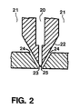
- Fig. 2 shows a cross section of the lower portion of the dispensing container 7 of the apparatus of Fig. 1.
- the dispensing container 7 comprises an interior chamber 20 for containing the polymer melt and two side wall chambers 21 for supplying air.
- the interior chamber 20 tapers downwards and in the outermost portion of the tapered section 22 an opening 23 is formed for the dispensing of polymer melt.
- a slot 24 is formed along the outermost portion of the tapered section 22, through which air is blown out from the side wall chambers 21.
- the air blown out through the slots 24 is directed to the tip of the interior chamber 20 where it is contacted with the dispensed polymer melt for the elongation and breaking up of the melt.
- Fig. 3 shows an apparatus 30 comprising a polymer melting chamber housing 31 for producing a polymer melt, which housing 31 via a tube 32 is connected with an oblong melt distribution chamber 33 connected via a number of tubes 34 with a number of vertical pressure guns 35 disposed in a row along the melt distribution chamber 33 and which comprise a channel formed nozzle.
- the housing 31 contains a melting chamber wherein a thermoplastic, solid polymer material supplied thereto, e.g. in the form of pellets, is heated by electric heating elements to melt it and from which the polymer melt obtained is subsequently pumped through the tube 32, the distribution chamber 33, the tubes 34 and the pressure guns 35 by a pump located in the housing 31.
- a thermoplastic, solid polymer material supplied thereto e.g. in the form of pellets
- the apparatus 30 comprises means (not shown) for supplying air to each pressure gun 35.
- the air supplied to the pressure guns 35 is divided in each pressure gun 35 into a number of elongation streams and a number of orientation streams.
- the elongation streams serve to elongate the polymer material dispensed from the nozzle and optionally to break it up in individual fibres and/or filaments 36, whereas the orientation streams primarily serve to distribute the fibres and/or filaments 36 obtained in the longitudinal direction of the pressure gun row and optionally also to further elongate and break up the polymer material.
- the pressure guns 35 comprise a number of channels for directing the elongation streams, said channels debouching close to the nozzle channel and having a form which impart to the individual partial streams such a direction that the major portion of the formed polymer fibres and/or filaments 36 in a distance from the mouth of the nozzle are distributed in such a manner that the polymer material forms an approximately circular deposit on a horizontal stationary base.
- the pressure guns 35 comprise a number of channels for directing the orientation streams, said channels debouching in both a greater axial and a greater radial distance from the mouth of the channel formed nozzle than the orientation streams.
- the channels have a form which imparts to the partial streams such a direction that the major portion of the polymer fibres and/or filaments 36 are distributed in such a manner that the polymer material forms an oblong approximately oval deposit on a horizontal stationary base.
- the row of pressure guns 35 is disposed above a mineral fibre web 37 conveyed on a conveyor belt (not shown) transversely to the direction of advance of the web.
- the pressure guns 35 are equally spaced and extend over the entire width of the mineral fibre web 37.
- the fibres and/or filaments 36 dispensed from the pressure guns 35 are deposited on the upper side of the mineral fibre web 37 so as to form a coherent netting 38.
- a suction box 39 is located vis-a-vis the row of pressure guns 35 and between two conveyor belts (not shown), said suction box removing the air blown out from the pressure guns 35.
- the suction box is connected with a suction pump (not shown) via a pipe 40.
- the tests were carried out by use of a melt blow apparatus comprising a dispensing chamber located above the rock fibre webs and having a greater length than the width of the rock fibre webs and a suction box located below the said webs and vis-a-vis the dispensing chamber.
- the distance between the nozzles of the dispensing chamber and the upper side of the rock fibre webs was about 0.5 m.
- the rock fibre webs contained about 1.6% by weight of a binder in the form of phenol formaldehyde and had a specific weight of about 30 kg/m3 and a thickness of about 100 mm.
- the webs had a surface temperature of about 20°C.
- the polymer starting material used was a polyester in the form of a granulate marketed under the name EMS G760.
- the polyester was melted in an extruder and subsequently the melt obtained was extruded through the nozzles in the dispensing chamber and the extruded polymer strings were elongated by means of two gas streams and broken up to form separate fibres which were deposited on the upper surface and the side edge surfaces of the rock fibre webs.
- coated rock fibre webs produced had a tactility corresponding completely to the tactility of the prior art mineral fibre elements having a surface coating consisting of polyester.
- the polyester fibres applied had an average diameter of about 5 ⁇ m.
- the surface coating having a surface weight of 10 g/m2 had a thermal value of 0.3 MJ/m2, whereas the coating having a surface weight of 15 g/m2 had a thermal value of 0.45 MJ/m2.
- a surface coating consisting of a non-woven material of polyester and having a surface weight of 20 g/m2 and an adhesive layer of phenol formaldehyde resin has a thermal value of 1.0 MJ/m2.
- the tensile strength of this web was determined and as a result it was found that the tensile strength was 25% higher than the tensile strength of a corresponding rock fibre web without any surface coating.
- An initial test series was carried out by use of a melt spray apparatus wherein the pressure guns were located in a row above the rock fibre webs and spaced 10 cm apart, and each individual pressure gun laid out a layer of a width of from 10 cm to 15 cm.
- the distance between the nozzle mouths of the pressure guns and the upper side of the mineral fibre webs was of from about 0.3 to about 0.5 m.
- Air having a pressure of 4-5 bars and a temperature of 210-230°C was used as elongation and orientation gas.
- the rock fibre webs contained about 1.6% by weight of a binder in the form of phenol formaldehyde and had a specific weight of about 30 kg/m3 and a thickness of about 100 mm.
- the webs had a surface temperature of about 20°C on the application of the surface coating.
- a polyester marketed by the company Hüls under the name Dynapol S 390 was used as polymer material.
- the polyester was melted in a melting vessel at a temperature of about 220°C, and subsequently the melt obtained was extruded through the nozzles in the pressure guns, and the extruded polymer strings were elongated by a number of air streams and broken up so as to form separate fibres which were deposited on the surface of the rock fibre webs. All the sides of the webs were coated.
- the coating formed had a surface weight of 15 g/m2 and the adhesion between the rock fibre material and the coating was satisfactory as tearing tests showed that the rock fibre material was spread out in separate layers before the surface coating was torn off the rock fibre material.
- the polyester fibres applied had an average diameter of about 40 ⁇ m. The coating was tactile.
- Another test series was carried out by use of a melt spray apparatus comprising means for mixing a gas into the polymer melt.
- the remaining characteristics of the apparatus were identical with those of the apparatus used in the initial test row, just as the remaining test conditions were identical with those used in the initial test series.
- the polymer was melted in a melting vessel at a temperature of about 160°C, and subsequently a foaming gas in the form of nitrogen was admixed with the melt and the mixture of melt and gas obtained was then extruded through the nozzles in the pressure guns.
- the extruded melt/gas mixture was then elongated by a number of air streams and broken up so as to form separate fibres which were deposited on the surface of the rock fibre webs. All the sides of the webs were coated.
- the surface coating formed had a surface weight of 15 g/m2, and the adhesion between the rock fibre material and the coating was satisfactory, as tearing tests showed that the rock fibre material was broken up in separate layers before the surface coating was torn off the rock fibre material.
- the polymer fibres applied had an average diameter of about 80 ⁇ m, and the netting formed covered a greater portion of the surface of the rock fibre material than the netting formed in the initial test series, but the netting consisting of foamed fibres was still permeable to air, however.
- the coating formed in the second test series had an increased tactility and rock fibre retention capacity as compared to the coating formed in the initial test series.
Landscapes
- Engineering & Computer Science (AREA)
- Textile Engineering (AREA)
- Laminated Bodies (AREA)
- Chemical Or Physical Treatment Of Fibers (AREA)
- Spinning Methods And Devices For Manufacturing Artificial Fibers (AREA)
- Application Of Or Painting With Fluid Materials (AREA)
- Nonwoven Fabrics (AREA)
- Inorganic Fibers (AREA)
- Silicates, Zeolites, And Molecular Sieves (AREA)
- Artificial Filaments (AREA)
Claims (10)
- Verfahren zur Herstellung von Mineralfaserbauteilen, die eine Mineralfaserbasisschicht (12, 37) mit einer Oberflächenbeschichtung (13, 38) in Form eines fasrigen Geflechtes aus thermoplastischem Polymermaterial umfassen, wobei die Oberflächenbeschichtung auf wenigstens einem Teil der Oberfläche der Baisschicht ausgebildet ist,
dadurch gekennzeichnet,
daß die Oberflächenbeschichtung direkt auf der Oberfläche der Basisschicht gebildet wird, daß die Oberflächenbeschichtung durch Erhitzen eines thermoplastischen Polymermaterials bis zur Schmelze gebildet wird und daß durch Verteilen der erhaltenen Polymerschmelze in Form von Fasern und/oder Filamenten auf der Oberfläche der Basisschicht und durch Abkühlen eine feste Schicht gebildet wird. - Verfahren nach Anspruch 1, dadurch gekennzeichnet, daß die Oberflächenbeschichtung (13, 38) ein Oberflächengewicht von 2 g/m² bis 50 g/m², vorzugsweise von 5 g/m² bis 20 g/m², besonders bevorzugt von 10 g/m² bis 15 g/m² hat.
- Verfahren nach den Ansprüchen 1 oder 2, dadurch gekennzeichnet, daß die Basisschicht (12, 37) die Form eines endlosen Gewebes, eines Gewebes, einer Matte oder einer Platte hat.
- Vorrichtung (1, 30) zur Durchführung des Verfahrens nach einem der Ansprüche 1 bis 3, dadurch gekennzeichnet, daß diese eine oder mehrere Einheiten umfaßt, wobei jede Einheit eine Einrichtung (5, 31) zum Schmelzen von thermoplastischem Polymermaterial, eine Anzahl von Düsen (23, 35), eine Einrichtung zum Extrudieren der erhaltenen Polymerschmelze durch die Düsen und zur Verteilung des extrudierten Polymermaterials auf der Oberfläche einer Mineralfaserbasisschicht (12, 37), und eine Einrichtung (24) zur Führung eines oder mehrerer Hochdruckgasströme dicht an den Düsen vorbei, so angebracht das extrudierte Polymermaterial zu elongieren, so daß dünne Filamente und/oder Fasern (11, 36) geformt werden, umfaßt.
- Vorrichtung (1, 30) nach Anspruch 4, dadurch gekennzeichnet, daß diese eine Einrichtung zum Halten und optional zum Befördern der Basisschicht umfaßt.
- Vorrichtung (1, 30) nach Anspruch 4 oder 5, dadurch gekennzeichnet, daß diese eine Saugeinrichtung (14, 15, 39, 40) umfaßt.
- Vorrichtung (1) nach einem der Ansprüche 4 bis 6, dadurch gekennzeichnet, daß diese eine längliche Ausgabekammer (20), die über eine Pumpe in flüssigkeitsfördernder Verbindung mit der Schmelzeinrichtung (5) steht und an ihrem äußeren Ende eine Anzahl dichtstehender Düsen (23) aufweist, zwei sich entlang der Seitenwände der Ausgabekammer befindende Kammern (21), an deren Ende ein länglicher Schlitz (24) geformt ist, und eine Einrichtung zur Führung von Hochdruckgasströmen durch die besagten Seitenkammern und durch den Schlitz nach außen umfaßt.
- Vorrichtung (30) nach einem der Ansprüche 4 bis 6, dadurch gekennzeichnet, daß diese optional eine Einrichtung zum Mischen von Gasen in die Polymerschmelze umfaßt und daß diese eine Anzahl von Ausgabepressen (35), die jeweils eine Düse umfassen und über eine Pumpe in flüssigkeitsfördernder Verbindung mit der Schmelzeinrichtung (31) stehen, und eine Einrichtung zur Führung eines oder mehrerer Hochdruckgasströme durch die Öffnungen der einzelnen Ausgabepressen umfaßt.
- Vorrichtung (30) nach Anspruch 8, dadurch gekennzeichnet, daß eine oder mehrere Einheiten zusammen eine Anzahl von Ausgabepressen (35) umfassen, welche derart eingerichtet und/oder bewegt werden können, daß das von den Pressen emittierte Polymermaterial (36) über der ganzen Oberfläche der Basisschicht (37) verteilt werden kann.
- Vorrichtung (1) nach Anspruch 7, wobei die Vorrichtung eine Saugeinrichtung (14, 15) umfaßt, dadurch gekennzeichnet, daß diese eine Ausgabekammer (20) umfaßt, deren Länge größer ist, als die Abmessung der Basisschicht (12) in Richtung parallel zur beschriebenen Kammer.
Applications Claiming Priority (3)
| Application Number | Priority Date | Filing Date | Title |
|---|---|---|---|
| DK92267A DK26792D0 (da) | 1992-02-28 | 1992-02-28 | Fremgangsmaade til fremstilling af mineralfiberprodukt |
| DK267/92 | 1992-02-28 | ||
| PCT/DK1993/000064 WO1993016874A1 (en) | 1992-02-28 | 1993-02-23 | Process for preparing a mineral fibre element comprising a surface coating and apparatus for carrying out the process |
Publications (2)
| Publication Number | Publication Date |
|---|---|
| EP0629153A1 EP0629153A1 (de) | 1994-12-21 |
| EP0629153B1 true EP0629153B1 (de) | 1996-04-10 |
Family
ID=8091614
Family Applications (1)
| Application Number | Title | Priority Date | Filing Date |
|---|---|---|---|
| EP93905221A Expired - Lifetime EP0629153B1 (de) | 1992-02-28 | 1993-02-23 | Apparat und verfahren zur herstellung eines mineralfasergegenstandes mit oberflächenbeschichtung |
Country Status (13)
| Country | Link |
|---|---|
| EP (1) | EP0629153B1 (de) |
| AT (1) | ATE136498T1 (de) |
| AU (1) | AU3627093A (de) |
| CA (1) | CA2129737C (de) |
| CZ (1) | CZ206194A3 (de) |
| DE (1) | DE69302169T2 (de) |
| DK (2) | DK26792D0 (de) |
| ES (1) | ES2086221T3 (de) |
| FI (1) | FI106368B (de) |
| NO (1) | NO300720B1 (de) |
| PL (1) | PL171684B1 (de) |
| SK (1) | SK281388B6 (de) |
| WO (1) | WO1993016874A1 (de) |
Cited By (2)
| Publication number | Priority date | Publication date | Assignee | Title |
|---|---|---|---|---|
| US5849131A (en) * | 1995-01-12 | 1998-12-15 | Owens Corning Fiberglas Technology, Inc. | Method for applying adhesive to an insulation assembly |
| US5916393A (en) * | 1997-06-24 | 1999-06-29 | Owens Corning Fiberglas Technology, Inc. | Method for applying adhesive on a porous substrate |
Families Citing this family (12)
| Publication number | Priority date | Publication date | Assignee | Title |
|---|---|---|---|---|
| US5501872A (en) * | 1995-04-19 | 1996-03-26 | Exxon Chemical Patents, Inc. | Method and apparatus for coating a six-sided fibrous batting |
| EP0986663A1 (de) * | 1997-05-28 | 2000-03-22 | Rockwool International A/S | Anlage und verfahren zur herstellung von einem beschichteten mineralfasermaterial |
| EP0986662B1 (de) | 1997-05-28 | 2001-10-10 | Rockwool International A/S | Anlage und verfahren zur beschichtung von mineralfaserbahnen auf einer oder beiden seiten |
| US6054205A (en) * | 1997-05-29 | 2000-04-25 | Clark-Schwebel Tech-Fab Company | Glass fiber facing sheet and method of making same |
| DK200100038A (da) * | 2001-01-08 | 2002-01-09 | Rockwool Int | Isoleringselement |
| EP1312714A1 (de) | 2001-11-14 | 2003-05-21 | Rockwool International A/S | Vorrichtung zur Dämpfung von Vibrationen |
| US6905563B2 (en) * | 2002-12-24 | 2005-06-14 | Owens Corning Fiberglas Technology, Inc. | Method and apparatus for melt-blown fiber encapsulation |
| US7625828B2 (en) | 2004-01-08 | 2009-12-01 | Certainteed Corporation | Insulation product having nonwoven facing |
| US7544267B2 (en) | 2004-01-08 | 2009-06-09 | Certainteed Corporation | Method of making insulation product having nonwoven facing |
| DE102006028841B4 (de) * | 2005-06-21 | 2014-05-15 | Deutsche Rockwool Mineralwoll Gmbh & Co. Ohg | Dämmanordnung und Verfahren zur Herstellung eines Dämmstoffstreifens |
| CN106835407B (zh) * | 2017-02-24 | 2020-03-24 | 青岛晨韵电子商务有限公司 | 一种含高分子纤维的冬暖夏凉双面床罩及其加工工艺 |
| PL245005B1 (pl) * | 2022-03-28 | 2024-04-15 | Zygmunt Dziwak | Sposób powlekania materiałów włókninowych oraz urządzenie do realizacji sposobu do powlekania materiałów włókninowych |
Family Cites Families (3)
| Publication number | Priority date | Publication date | Assignee | Title |
|---|---|---|---|---|
| FI52440C (fi) * | 1975-09-04 | 1977-09-12 | Pekema Oy | Menetelmä ja laite sulan termoplastisen päällystysaineen pursottamisek si perusaineradalle siten, että päällysteaine on tietyiltä kohdin irti perusaineesta. |
| DK142064B (da) * | 1978-02-28 | 1980-08-18 | Rockwool Int | Mineraluldplade til termisk eller akustisk isolering. |
| SE452440B (sv) * | 1985-02-14 | 1987-11-30 | Tarkett Ab | Sett och anordning for framstellning av dekorativa plastbanor eller -plattor varvid sprutmunstycken och berbana forskjutes relativt varandra samt dekorativ plastbana eller -platta |
-
1992
- 1992-02-28 DK DK92267A patent/DK26792D0/da not_active Application Discontinuation
-
1993
- 1993-02-23 AU AU36270/93A patent/AU3627093A/en not_active Abandoned
- 1993-02-23 CZ CZ942061A patent/CZ206194A3/cs unknown
- 1993-02-23 WO PCT/DK1993/000064 patent/WO1993016874A1/en not_active Ceased
- 1993-02-23 CA CA002129737A patent/CA2129737C/en not_active Expired - Fee Related
- 1993-02-23 DK DK93905221.3T patent/DK0629153T3/da active
- 1993-02-23 PL PL93304886A patent/PL171684B1/pl not_active IP Right Cessation
- 1993-02-23 ES ES93905221T patent/ES2086221T3/es not_active Expired - Lifetime
- 1993-02-23 EP EP93905221A patent/EP0629153B1/de not_active Expired - Lifetime
- 1993-02-23 AT AT93905221T patent/ATE136498T1/de not_active IP Right Cessation
- 1993-02-23 DE DE69302169T patent/DE69302169T2/de not_active Expired - Fee Related
- 1993-02-23 SK SK945-94A patent/SK281388B6/sk unknown
-
1994
- 1994-08-16 NO NO943035A patent/NO300720B1/no not_active IP Right Cessation
- 1994-08-26 FI FI943925A patent/FI106368B/fi active
Cited By (2)
| Publication number | Priority date | Publication date | Assignee | Title |
|---|---|---|---|---|
| US5849131A (en) * | 1995-01-12 | 1998-12-15 | Owens Corning Fiberglas Technology, Inc. | Method for applying adhesive to an insulation assembly |
| US5916393A (en) * | 1997-06-24 | 1999-06-29 | Owens Corning Fiberglas Technology, Inc. | Method for applying adhesive on a porous substrate |
Also Published As
| Publication number | Publication date |
|---|---|
| FI106368B (fi) | 2001-01-31 |
| CZ206194A3 (en) | 1995-01-18 |
| DK26792D0 (da) | 1992-02-28 |
| FI943925A0 (fi) | 1994-08-26 |
| NO943035D0 (no) | 1994-08-16 |
| WO1993016874A1 (en) | 1993-09-02 |
| DE69302169T2 (de) | 1996-11-21 |
| ATE136498T1 (de) | 1996-04-15 |
| CA2129737A1 (en) | 1993-08-29 |
| CA2129737C (en) | 2004-11-02 |
| EP0629153A1 (de) | 1994-12-21 |
| NO943035L (no) | 1994-08-16 |
| ES2086221T3 (es) | 1996-06-16 |
| DK0629153T3 (da) | 1996-08-05 |
| DE69302169D1 (de) | 1996-05-15 |
| FI943925L (fi) | 1994-08-26 |
| SK281388B6 (sk) | 2001-03-12 |
| AU3627093A (en) | 1993-09-13 |
| PL171684B1 (pl) | 1997-06-30 |
| NO300720B1 (no) | 1997-07-14 |
| SK94594A3 (en) | 1995-06-07 |
Similar Documents
| Publication | Publication Date | Title |
|---|---|---|
| CA2129737C (en) | Process for preparing a mineral fibre element comprising a surface coating and apparatus for carrying out the process | |
| US6203646B1 (en) | Process for preparing a mineral fibre element comprising a surface coating | |
| CA2248258C (en) | Process of making spun-bonded web | |
| AU759720B2 (en) | Method and apparatus for introducing in continuous a substance in liquid phase into plastics granules | |
| CA2351104C (en) | Apparatus for making nonwoven fabric | |
| EP0986662A1 (de) | Anlage und verfahren zur beschichtung von mineralfaserbahnen auf einer oder beiden seiten | |
| KR20010032391A (ko) | 광섬유와 유기섬유가 일체된 섬유성 절연물과 이런 섬유성절연물로 절연된 빌딩구조물 | |
| KR20020081404A (ko) | 목질 성형체 및 그 제조방법 | |
| KR20010032354A (ko) | 유기질 섬유 및 광물섬유의 팩을 성형하는 방법 | |
| US6135747A (en) | Apparatus for making mineral fiber insulation batt impregnated with extruded synthetic fibers | |
| WO1998058800A1 (en) | Method for applying adhesive on a porous substrate | |
| JP2001524613A (ja) | 繊維状パックを製造する方法 | |
| CN1319692A (zh) | 无纺布的制造方法及其装置 | |
| US6066369A (en) | Method of and apparatus for producing a composite web | |
| WO1998054388A1 (en) | Plant and process for producing a coated mineral fibre element | |
| JP3676248B2 (ja) | 木質成形体の製造方法 | |
| JP3579372B2 (ja) | 木質成形体の製造方法 | |
| CA2243736C (en) | Mineral fiber insulation batt impregnated with extruded synthetic fibers, and apparatus for making same | |
| JP3655574B2 (ja) | 木質成形体の製造方法 | |
| JP2767355B2 (ja) | 加飾性積層成形品の製造方法およびその装置 | |
| GB2054681A (en) | Flexible sheet materials | |
| CA2131200A1 (en) | Process for producing particles from plastics | |
| FI106367B (fi) | Rainanmuotoiset vaahtomuovilevyt polyolefiineista | |
| WO1991001211A1 (en) | Method and means for the production of pile surfaced products from thermoplastics | |
| JPH03227446A (ja) | 熱可塑性プラスチック製紡糸繊維から成るフリースの製造方法 |
Legal Events
| Date | Code | Title | Description |
|---|---|---|---|
| PUAI | Public reference made under article 153(3) epc to a published international application that has entered the european phase |
Free format text: ORIGINAL CODE: 0009012 |
|
| 17P | Request for examination filed |
Effective date: 19940909 |
|
| AK | Designated contracting states |
Kind code of ref document: A1 Designated state(s): AT BE CH DE DK ES FR GB IT LI NL SE |
|
| 17Q | First examination report despatched |
Effective date: 19950515 |
|
| GRAA | (expected) grant |
Free format text: ORIGINAL CODE: 0009210 |
|
| AK | Designated contracting states |
Kind code of ref document: B1 Designated state(s): AT BE CH DE DK ES FR GB IT LI NL SE |
|
| REF | Corresponds to: |
Ref document number: 136498 Country of ref document: AT Date of ref document: 19960415 Kind code of ref document: T |
|
| REF | Corresponds to: |
Ref document number: 69302169 Country of ref document: DE Date of ref document: 19960515 |
|
| REG | Reference to a national code |
Ref country code: ES Ref legal event code: FG2A Ref document number: 2086221 Country of ref document: ES Kind code of ref document: T3 |
|
| ITF | It: translation for a ep patent filed | ||
| ET | Fr: translation filed | ||
| REG | Reference to a national code |
Ref country code: CH Ref legal event code: NV Representative=s name: PATENTANWALTSBUERO EDER AG |
|
| REG | Reference to a national code |
Ref country code: DK Ref legal event code: T3 |
|
| PLBE | No opposition filed within time limit |
Free format text: ORIGINAL CODE: 0009261 |
|
| 26N | No opposition filed | ||
| REG | Reference to a national code |
Ref country code: FR Ref legal event code: CL |
|
| REG | Reference to a national code |
Ref country code: GB Ref legal event code: IF02 |
|
| PGFP | Annual fee paid to national office [announced via postgrant information from national office to epo] |
Ref country code: ES Payment date: 20050323 Year of fee payment: 13 |
|
| PG25 | Lapsed in a contracting state [announced via postgrant information from national office to epo] |
Ref country code: ES Free format text: LAPSE BECAUSE OF NON-PAYMENT OF DUE FEES Effective date: 20060224 |
|
| REG | Reference to a national code |
Ref country code: ES Ref legal event code: FD2A Effective date: 20060224 |
|
| PGFP | Annual fee paid to national office [announced via postgrant information from national office to epo] |
Ref country code: CH Payment date: 20080214 Year of fee payment: 16 |
|
| PGFP | Annual fee paid to national office [announced via postgrant information from national office to epo] |
Ref country code: IT Payment date: 20080226 Year of fee payment: 16 Ref country code: GB Payment date: 20080220 Year of fee payment: 16 Ref country code: DE Payment date: 20080221 Year of fee payment: 16 |
|
| PGFP | Annual fee paid to national office [announced via postgrant information from national office to epo] |
Ref country code: DK Payment date: 20090213 Year of fee payment: 17 Ref country code: AT Payment date: 20090211 Year of fee payment: 17 |
|
| PGFP | Annual fee paid to national office [announced via postgrant information from national office to epo] |
Ref country code: NL Payment date: 20090203 Year of fee payment: 17 |
|
| PGFP | Annual fee paid to national office [announced via postgrant information from national office to epo] |
Ref country code: BE Payment date: 20090225 Year of fee payment: 17 |
|
| PGFP | Annual fee paid to national office [announced via postgrant information from national office to epo] |
Ref country code: SE Payment date: 20090206 Year of fee payment: 17 |
|
| REG | Reference to a national code |
Ref country code: CH Ref legal event code: PL |
|
| GBPC | Gb: european patent ceased through non-payment of renewal fee |
Effective date: 20090223 |
|
| PG25 | Lapsed in a contracting state [announced via postgrant information from national office to epo] |
Ref country code: LI Free format text: LAPSE BECAUSE OF NON-PAYMENT OF DUE FEES Effective date: 20090228 Ref country code: CH Free format text: LAPSE BECAUSE OF NON-PAYMENT OF DUE FEES Effective date: 20090228 |
|
| PGFP | Annual fee paid to national office [announced via postgrant information from national office to epo] |
Ref country code: FR Payment date: 20090213 Year of fee payment: 17 |
|
| PG25 | Lapsed in a contracting state [announced via postgrant information from national office to epo] |
Ref country code: DE Free format text: LAPSE BECAUSE OF NON-PAYMENT OF DUE FEES Effective date: 20090901 |
|
| PG25 | Lapsed in a contracting state [announced via postgrant information from national office to epo] |
Ref country code: GB Free format text: LAPSE BECAUSE OF NON-PAYMENT OF DUE FEES Effective date: 20090223 |
|
| BERE | Be: lapsed |
Owner name: *ROCKWOOL INTERNATIONAL A/S Effective date: 20100228 |
|
| REG | Reference to a national code |
Ref country code: NL Ref legal event code: V1 Effective date: 20100901 |
|
| REG | Reference to a national code |
Ref country code: DK Ref legal event code: EBP |
|
| EUG | Se: european patent has lapsed | ||
| REG | Reference to a national code |
Ref country code: FR Ref legal event code: ST Effective date: 20101029 |
|
| PG25 | Lapsed in a contracting state [announced via postgrant information from national office to epo] |
Ref country code: AT Free format text: LAPSE BECAUSE OF NON-PAYMENT OF DUE FEES Effective date: 20100223 |
|
| PG25 | Lapsed in a contracting state [announced via postgrant information from national office to epo] |
Ref country code: NL Free format text: LAPSE BECAUSE OF NON-PAYMENT OF DUE FEES Effective date: 20100901 Ref country code: FR Free format text: LAPSE BECAUSE OF NON-PAYMENT OF DUE FEES Effective date: 20100301 Ref country code: DK Free format text: LAPSE BECAUSE OF NON-PAYMENT OF DUE FEES Effective date: 20100228 |
|
| PG25 | Lapsed in a contracting state [announced via postgrant information from national office to epo] |
Ref country code: BE Free format text: LAPSE BECAUSE OF NON-PAYMENT OF DUE FEES Effective date: 20100228 |
|
| PG25 | Lapsed in a contracting state [announced via postgrant information from national office to epo] |
Ref country code: IT Free format text: LAPSE BECAUSE OF NON-PAYMENT OF DUE FEES Effective date: 20090223 |
|
| PG25 | Lapsed in a contracting state [announced via postgrant information from national office to epo] |
Ref country code: SE Free format text: LAPSE BECAUSE OF NON-PAYMENT OF DUE FEES Effective date: 20100224 |