EP0629412A2 - Coeur artificiel auxiliaire implanté dans un ventricule du coeur - Google Patents
Coeur artificiel auxiliaire implanté dans un ventricule du coeur Download PDFInfo
- Publication number
- EP0629412A2 EP0629412A2 EP94105896A EP94105896A EP0629412A2 EP 0629412 A2 EP0629412 A2 EP 0629412A2 EP 94105896 A EP94105896 A EP 94105896A EP 94105896 A EP94105896 A EP 94105896A EP 0629412 A2 EP0629412 A2 EP 0629412A2
- Authority
- EP
- European Patent Office
- Prior art keywords
- sealing liquid
- sealing
- dynamic
- artificial heart
- driving shaft
- Prior art date
- Legal status (The legal status is an assumption and is not a legal conclusion. Google has not performed a legal analysis and makes no representation as to the accuracy of the status listed.)
- Granted
Links
Images



Classifications
-
- A—HUMAN NECESSITIES
- A61—MEDICAL OR VETERINARY SCIENCE; HYGIENE
- A61M—DEVICES FOR INTRODUCING MEDIA INTO, OR ONTO, THE BODY; DEVICES FOR TRANSDUCING BODY MEDIA OR FOR TAKING MEDIA FROM THE BODY; DEVICES FOR PRODUCING OR ENDING SLEEP OR STUPOR
- A61M60/00—Blood pumps; Devices for mechanical circulatory actuation; Balloon pumps for circulatory assistance
- A61M60/80—Constructional details other than related to driving
- A61M60/802—Constructional details other than related to driving of non-positive displacement blood pumps
- A61M60/827—Sealings between moving parts
- A61M60/829—Sealings between moving parts having a purge fluid supply
-
- A—HUMAN NECESSITIES
- A61—MEDICAL OR VETERINARY SCIENCE; HYGIENE
- A61M—DEVICES FOR INTRODUCING MEDIA INTO, OR ONTO, THE BODY; DEVICES FOR TRANSDUCING BODY MEDIA OR FOR TAKING MEDIA FROM THE BODY; DEVICES FOR PRODUCING OR ENDING SLEEP OR STUPOR
- A61M60/00—Blood pumps; Devices for mechanical circulatory actuation; Balloon pumps for circulatory assistance
- A61M60/10—Location thereof with respect to the patient's body
- A61M60/122—Implantable pumps or pumping devices, i.e. the blood being pumped inside the patient's body
- A61M60/165—Implantable pumps or pumping devices, i.e. the blood being pumped inside the patient's body implantable in, on, or around the heart
- A61M60/17—Implantable pumps or pumping devices, i.e. the blood being pumped inside the patient's body implantable in, on, or around the heart inside a ventricle, e.g. intraventricular balloon pumps
-
- A—HUMAN NECESSITIES
- A61—MEDICAL OR VETERINARY SCIENCE; HYGIENE
- A61M—DEVICES FOR INTRODUCING MEDIA INTO, OR ONTO, THE BODY; DEVICES FOR TRANSDUCING BODY MEDIA OR FOR TAKING MEDIA FROM THE BODY; DEVICES FOR PRODUCING OR ENDING SLEEP OR STUPOR
- A61M60/00—Blood pumps; Devices for mechanical circulatory actuation; Balloon pumps for circulatory assistance
- A61M60/10—Location thereof with respect to the patient's body
- A61M60/122—Implantable pumps or pumping devices, i.e. the blood being pumped inside the patient's body
- A61M60/165—Implantable pumps or pumping devices, i.e. the blood being pumped inside the patient's body implantable in, on, or around the heart
- A61M60/17—Implantable pumps or pumping devices, i.e. the blood being pumped inside the patient's body implantable in, on, or around the heart inside a ventricle, e.g. intraventricular balloon pumps
- A61M60/174—Implantable pumps or pumping devices, i.e. the blood being pumped inside the patient's body implantable in, on, or around the heart inside a ventricle, e.g. intraventricular balloon pumps discharging the blood to the ventricle or arterial system via a cannula internal to the ventricle or arterial system
-
- A—HUMAN NECESSITIES
- A61—MEDICAL OR VETERINARY SCIENCE; HYGIENE
- A61M—DEVICES FOR INTRODUCING MEDIA INTO, OR ONTO, THE BODY; DEVICES FOR TRANSDUCING BODY MEDIA OR FOR TAKING MEDIA FROM THE BODY; DEVICES FOR PRODUCING OR ENDING SLEEP OR STUPOR
- A61M60/00—Blood pumps; Devices for mechanical circulatory actuation; Balloon pumps for circulatory assistance
- A61M60/20—Type thereof
- A61M60/205—Non-positive displacement blood pumps
- A61M60/216—Non-positive displacement blood pumps including a rotating member acting on the blood, e.g. impeller
- A61M60/237—Non-positive displacement blood pumps including a rotating member acting on the blood, e.g. impeller the blood flow through the rotating member having mainly axial components, e.g. axial flow pumps
-
- A—HUMAN NECESSITIES
- A61—MEDICAL OR VETERINARY SCIENCE; HYGIENE
- A61M—DEVICES FOR INTRODUCING MEDIA INTO, OR ONTO, THE BODY; DEVICES FOR TRANSDUCING BODY MEDIA OR FOR TAKING MEDIA FROM THE BODY; DEVICES FOR PRODUCING OR ENDING SLEEP OR STUPOR
- A61M60/00—Blood pumps; Devices for mechanical circulatory actuation; Balloon pumps for circulatory assistance
- A61M60/40—Details relating to driving
- A61M60/403—Details relating to driving for non-positive displacement blood pumps
- A61M60/408—Details relating to driving for non-positive displacement blood pumps the force acting on the blood contacting member being mechanical, e.g. transmitted by a shaft or cable
- A61M60/411—Details relating to driving for non-positive displacement blood pumps the force acting on the blood contacting member being mechanical, e.g. transmitted by a shaft or cable generated by an electromotor
- A61M60/416—Details relating to driving for non-positive displacement blood pumps the force acting on the blood contacting member being mechanical, e.g. transmitted by a shaft or cable generated by an electromotor transmitted directly by the motor rotor drive shaft
-
- A—HUMAN NECESSITIES
- A61—MEDICAL OR VETERINARY SCIENCE; HYGIENE
- A61M—DEVICES FOR INTRODUCING MEDIA INTO, OR ONTO, THE BODY; DEVICES FOR TRANSDUCING BODY MEDIA OR FOR TAKING MEDIA FROM THE BODY; DEVICES FOR PRODUCING OR ENDING SLEEP OR STUPOR
- A61M60/00—Blood pumps; Devices for mechanical circulatory actuation; Balloon pumps for circulatory assistance
- A61M60/80—Constructional details other than related to driving
- A61M60/802—Constructional details other than related to driving of non-positive displacement blood pumps
- A61M60/81—Pump housings
- A61M60/812—Vanes or blades, e.g. static flow guides
-
- A—HUMAN NECESSITIES
- A61—MEDICAL OR VETERINARY SCIENCE; HYGIENE
- A61M—DEVICES FOR INTRODUCING MEDIA INTO, OR ONTO, THE BODY; DEVICES FOR TRANSDUCING BODY MEDIA OR FOR TAKING MEDIA FROM THE BODY; DEVICES FOR PRODUCING OR ENDING SLEEP OR STUPOR
- A61M60/00—Blood pumps; Devices for mechanical circulatory actuation; Balloon pumps for circulatory assistance
- A61M60/80—Constructional details other than related to driving
- A61M60/802—Constructional details other than related to driving of non-positive displacement blood pumps
- A61M60/818—Bearings
- A61M60/825—Contact bearings, e.g. ball-and-cup or pivot bearings
-
- A—HUMAN NECESSITIES
- A61—MEDICAL OR VETERINARY SCIENCE; HYGIENE
- A61M—DEVICES FOR INTRODUCING MEDIA INTO, OR ONTO, THE BODY; DEVICES FOR TRANSDUCING BODY MEDIA OR FOR TAKING MEDIA FROM THE BODY; DEVICES FOR PRODUCING OR ENDING SLEEP OR STUPOR
- A61M60/00—Blood pumps; Devices for mechanical circulatory actuation; Balloon pumps for circulatory assistance
- A61M60/80—Constructional details other than related to driving
- A61M60/802—Constructional details other than related to driving of non-positive displacement blood pumps
- A61M60/827—Sealings between moving parts
-
- A—HUMAN NECESSITIES
- A61—MEDICAL OR VETERINARY SCIENCE; HYGIENE
- A61M—DEVICES FOR INTRODUCING MEDIA INTO, OR ONTO, THE BODY; DEVICES FOR TRANSDUCING BODY MEDIA OR FOR TAKING MEDIA FROM THE BODY; DEVICES FOR PRODUCING OR ENDING SLEEP OR STUPOR
- A61M60/00—Blood pumps; Devices for mechanical circulatory actuation; Balloon pumps for circulatory assistance
- A61M60/80—Constructional details other than related to driving
- A61M60/855—Constructional details other than related to driving of implantable pumps or pumping devices
- A61M60/871—Energy supply devices; Converters therefor
- A61M60/873—Energy supply devices; Converters therefor specially adapted for wireless or transcutaneous energy transfer [TET], e.g. inductive charging
-
- A—HUMAN NECESSITIES
- A61—MEDICAL OR VETERINARY SCIENCE; HYGIENE
- A61M—DEVICES FOR INTRODUCING MEDIA INTO, OR ONTO, THE BODY; DEVICES FOR TRANSDUCING BODY MEDIA OR FOR TAKING MEDIA FROM THE BODY; DEVICES FOR PRODUCING OR ENDING SLEEP OR STUPOR
- A61M60/00—Blood pumps; Devices for mechanical circulatory actuation; Balloon pumps for circulatory assistance
- A61M60/10—Location thereof with respect to the patient's body
- A61M60/122—Implantable pumps or pumping devices, i.e. the blood being pumped inside the patient's body
- A61M60/126—Implantable pumps or pumping devices, i.e. the blood being pumped inside the patient's body implantable via, into, inside, in line, branching on, or around a blood vessel
- A61M60/148—Implantable pumps or pumping devices, i.e. the blood being pumped inside the patient's body implantable via, into, inside, in line, branching on, or around a blood vessel in line with a blood vessel using resection or like techniques, e.g. permanent endovascular heart assist devices
-
- A—HUMAN NECESSITIES
- A61—MEDICAL OR VETERINARY SCIENCE; HYGIENE
- A61M—DEVICES FOR INTRODUCING MEDIA INTO, OR ONTO, THE BODY; DEVICES FOR TRANSDUCING BODY MEDIA OR FOR TAKING MEDIA FROM THE BODY; DEVICES FOR PRODUCING OR ENDING SLEEP OR STUPOR
- A61M60/00—Blood pumps; Devices for mechanical circulatory actuation; Balloon pumps for circulatory assistance
- A61M60/80—Constructional details other than related to driving
- A61M60/802—Constructional details other than related to driving of non-positive displacement blood pumps
- A61M60/818—Bearings
- A61M60/824—Hydrodynamic or fluid film bearings
Definitions
- This invention relates to an artificial heart, and more particularly an auxiliary artificial heart of an embedded type, embedded in the left or right ventricle of the heart in a human body, and operated at high reliability by preventing body fluids such as blood from adversely entering the artificial heart.
- Conventional artificial hearts are of a diaphragm type, of a sack type, of an axially symmetric type, of a centrifugal type, of a pusher plate type or the like. Each of these conventional artificial hearts delivers blood in place of a human heart or by bypassing it.
- an auxiliary artificial heart which is embedded in a ventricle of a human heart and has the tip end of a nozzle passing through an aorta valve or the like such that blood is delivered from the ventricle into an aorta through the nozzle.
- the artificial heart has such a structure that it does not suppress any function of the human heart when it is provided in the human heart and it delivers additional blood into the aorta when blood pumped out from the human heart due to its beats is insufficient.
- the blood is delivered not only by the artificial heart but also by the pulsing human heart due to its beats. Even if the operation of the artificial heart happens to stop, blood is delivered by the human heart due to its beats.
- an artificial heart has a pump body comprising a cylindrical axial-flow pump section, a nozzle section provided on its distal end and a driving section provided on the proximal end of the axial-flow pump section.
- the cardiac apex of a ventricle of a human heart is cut and a short cylindrical cardiac apex ring is embedded therein.
- the pump section and the nozzle section are inserted in the ventricle through the cardiac apex ring, and the distal end of the nozzle section is inserted in an aorta through its aorta valve or the like.
- the driving section which has a large volume is embedded in a portion of the thorax which is outside of the human heart.
- the artificial heart has the following problem in connection with the function of a shaft-sealing mechanism provided between the pump section and the driving section.
- a motor and other elements are housed in the driving section, and the rotor of the pump section is driven via driving shaft extending from the driving section to the pump section.
- Blood applied with a blood pressure flows through the pump section. In this state, blood is not allowed to enter the space in the driving section. If blood enters the space defined in the driving section, coagulation of blood occurs and the operation of the motor stops.
- the object of this invention is to provide an artificial heart which has a shaft-sealing mechanism for completely preventing blood from entering the interior of a driving section for a long time.
- An auxiliary artificial heart according to this invention inserted in a ventricle of a human heart, including a cylindrical cardiac apex ring embedded in the cardiac apex of the human heart by cutting the cardiac apex, and a main body of the artificial heart comprising a cylindrical axial-flow pump section inserted in the ventricle of the human heart through the cardiac apex ring, a nozzle section extending outward from the distal end of the pump section through the aorta valve of the human heart and a driving section provided on the proximal end of the pump section and disposed outside (or externally) of the human heart, for driving the pump section through a driving shaft.
- the sealing mechanism Between the driving section and the pump section is provided a sealing mechanism for maintaining the driving shaft in a liquid tight state so as to prevent blood from entering the interior of the driving section from the pump section.
- the sealing mechanism defines a sealing liquid chamber surrounding the driving shaft at the driving section and a sealing liquid is filled in the sealing liquid chamber.
- the sealing liquid includes a physiological sodium chloride solution or an anticoagulant such as heparin, and the sealing liquid chamber communicates with a sealing liquid bag made of flexible material, filled with the sealing liquid and embedded in the human body.
- the sealing mechanism is provided with an oil seal made of elastic material, closely fitted on the outer peripheral surface of the driving shaft due to its elastic deformation and forming a lubricating film of the sealing liquid between the peripheral surface of the driving shaft and the oil seal.
- the pump section is driven by a motor or the like driving unit housed in the driving section.
- the pump section sucks blood from a ventricle of a human heart and discharges it into an aorta from the nozzle section of the distal end of the pump section by bypassing the aorta valve or the like.
- blood is delivered to the aorta not only by the beats of the human heart but also by means of the artificial heart.
- the artificial heart supplements insufficient amount of blood which is not provided by the human heart, whereby it is ensured that the necessary amount of blood can be delivered.
- the volume of the pump section is smaller than the volume of the ventricle of the human heart when it contract most so as not to prevent natural beats of the human heart.
- the sealing mechanism prevents blood from entering the driving section from the pump section.
- the sealing mechanism defines a sealing liquid chamber at the driving section, and a sealing liquid such as a physiological sodium chloride solution is filled in the sealing liquid chamber. Sealing and lubrication of the sealing mechanism are ensured by the sealing liquid, and blood is securely prevented from entering the interior of the driving section from the sealing mechanism.
- the sealing mechanism is provided with an oil seal which forms a lubricant film of the dealing liquid between the oil seal and the outer peripheral surface of the driving shaft and is elastically closely fitted on the outer peripheral surface of the driving shaft for securely preventing the entrance of blood such that the oil seal is not worn and has high durability.
- the oil seal can be designed such that the lubricant film formed between the oil seal and the outer peripheral surface of the driving shaft delivers blood in only one direction toward the pump section. This structure ensures the prevent in of blood from entering the interior of the driving section.
- the sealing liquid chamber communicates with the sealing liquid bag embedded in the human thorax or the like.
- a sealing liquid is supplemented from the sealing liquid bag and thus can be supplied to the sealing liquid chamber for a long time.
- the driving shaft uses a dynamic pressure bearing made of ceramic material operated in the sealing liquid.
- a coating film is formed between the sliding surfaces due to the dynamic pressure of the sealing liquid, thereby reducing rotational resistance of the bearing and preventing its wear, leading to high reliability.
- the dynamic pressure bearing When the driving shaft is rotated, the dynamic pressure bearing generates dynamic pressure.
- the dynamic pressure provided a liquid seal between between the sealing liquid chamber and the driving section. The sealing liquid is thereby prevented from flowing from the sealing liquid chamber into the driving section.
- the dynamic pressure bearing which is mounted on the distal end portion of the driving shaft, supplied the sealing liquid to the oil seal. Hence, the sealing liquid circulates in the artificial heart, preventing foreign body from depositing.
- a metal plating is formed on the outer peripheral surface of the driving shaft. Tetrafluoroethylene and its derivatives are made eutectic in the metal plating film, thereby improving not only lubricating properties between the driving shaft and the oil seal but also durability.
- the metal plating film of this kind is water-repellent and is well compatible with living body. Any component that contacts blood or the like may be covered entirely with such a metal plating film.
- FIG. 1 shows an artificial heart of this invention in a state embedded in the left ventricle B of the heart A of a patient (hereinafter referred to as the "human heart").
- a cardiac apex, a left atrium, a mitral valve, an aorta valve and an aorta are designated by C, D, E, F and G, respectively.
- the artificial heart 1 comprises a cardiac valve ring 2 and the main body 3 of the artificial heart.
- the cardiac valve ring 2 is a short cylindrical member having a flange and is embedded in the human heart A through the cardiac apex C of the human heart A after the cardiac apex C has been cut.
- the main body 3 of the artificial heart 1 comprises a pump section 4, a nozzle section 6 provided on the distal end of the pump section 4 and a driving section 5 provided on the proximal end of the pump section 4.
- the pump section 4 and the nozzle section 6 are inserted in the left ventricle B through the cardiac apex ring 2, and the nozzle section 6 is further inserted in the aorta G through the central portion of the aorta valve F. Liquid tightness is ensured between the cardiac apex ring 2 and the main body 3 by means of a ordinary sealing mechanism, for example, a sealing member 8.
- the pump section 4 is a relatively small cylindrical member and it has a smaller volume than the volume of the left ventricle B when it contracts most so as not to prevent natural beats of the human heart A.
- a small axial-flow pump which is driven by a motor provided in the driving section 5.
- the pump section 4 sucks blood from the left ventricle B at a suction port 7 formed in the outer peripheral surface of the section 4 and discharges the blood form the distal end of the nozzle section 6 into the aorta G with the aorta valve F bypassed.
- the nozzle section 6 passing through the central portion of the aorta valve F is made of soft synthetic resin material such that it does not suppress the function of the aorta valve F and it does not injure the aorta valve F.
- the driving section 5 is embedded in a portion of the thorax outside of the human heart A.
- a motor and other elements such as electric cells and electronic control elements if they are required.
- the driving section 5 is connected by means of electric wires 9 to a non-contact type electrode 10 embedded in a portion of the human body close to his skin H. A necessary electric power is supplied from an external electric source (not shown) to the driving section 5 through the electrode 10.
- the driving section 5 is further connected to a sealing liquid bag 12 by a flexible tube 11.
- the sealing liquid bag 12 is made of flexible material and filled with a sealing liquid such as a physiological sodium chloride solution.
- the sealing liquid bag 12 is embedded in a suitable portion of the body of the patient, such as the thorax or the abdominal cavity.
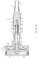
- the pump section 4 has a cylindrical casing 21 which is reduced in diameter at its distal end portion to form the nozzle section 6 and is connected at its proximal end portion to the driving section 5 by an extension 24.
- an axial-flow pump such as a propeller 22 and a plurality of guide vanes 23 for rectifying a blood flow.
- the suction port 7 is formed in the outer peripheral surface of the casing 21.
- a continuous blood passage extending from the suction port 7 to the nozzle section 6 via the propeller 22 and the guide vanes 23.
- a thin cylindrical nozzle tube 25 made of flexible synthetic resin material is mounted on the nozzle section 6.
- the nozzle tube 25 is designed so as to improve the contacting properties of the nozzle tube 25 with the ventricle valve F, prevent injure of the ventricle valve F and prevent the function of the ventricle valve F form being suppressed.
- the nozzle tube 25 is a flexible thin cylindrical member. Thus, when the artificial heart happens to be out of order, the nozzle tube 25 is collapsed by the blood pressure in the aorta G so as to act as a check valve for preventing blood from flowing backward from the aorta G to the left ventricle B.
- the distal end portion of the driving shaft 26 is connected to the propeller 22.
- the driving shaft 26 passes through the extension 24 and extends to the interior of the driving section 5.
- a motor having a stator coil 32 and a rotor 33.
- the proximal end portion of the driving shaft 26 is connected to the rotor 33.
- a cover 34 seals the driving section 5 hermetically.
- the blood flow passage in the pump section 4 is made smooth.
- the center portion of the pump section 4 has a boss portion 61, in which the driving shaft 26 and the bearing 28 are inserted.
- the sealing mechanism 31 is located in the distal end of the boss section 61, and has a conical oil seal.
- the oil seal is fitted in the conical depression formed in the rear end of a propeller boss 63 of the propeller 22, with a small gap formed between the oil seal and the conical depression.
- the guide vane 23 has a boss 64 which opposes the front end of the propeller boss 63 and is located at a short distance therefrom. No steps are made between the inner peripheral surface of the casing 21 and the outer surfaces of the boss section 61, propeller boss 63 and boss 64.
- a smooth annular blood flow passage is therefore formed between the inner peripheral surface of the casing 21 and the outer surface so the components 61, 63 and 64.
- the suction port 7 is formed in the proximal part of the boss section 61.
- a plurality of flow regulating vanes 62 are arranged between the suction port 7 and the propeller 22.
- the blood flow passage is smooth as described above, the blood can flow smoothly, enhancing the pump efficiency and reducing the number of places where the blood does not flow. Hence, the possibility of thrombi is decreased.
- the distal end portion of the driving shaft 26 is supported by a bearing 28 made of ceramic material, and the proximal end portion of the driving shaft 26 is supported by dynamic pressure bearings 35 and 36 made of ceramic material in the driving section 5.
- a sealing mechanism 31 for performing sealing between the interior of the pump section 4 and the interior of the driving section 5 such that blood in the pump section 4 is prevented from entering the driving section 5.
- a sealing liquid chamber 30 surrounding the driving shaft 26.
- a sealing liquid such as a physiological sodium chloride solution is filled in the sealing liquid chamber 30.
- a blood coagulant such as heparin or any other chemical agents, if required are added to the sodium chloride solution.
- the sealing liquid is not limited to physiological chloride solution. Heparin may be sued as sealing liquid.
- An axial groove 27 is formed between the outer.
- the space is filled with the sealing liquid and substantially forms part of the sealing liquid chamber 30.
- an axial groove 37 which communicates with the sealing liquid chamber 30 and a narrow passage 38 formed in the inside wall of the driving section 5.
- the sealing liquid chamber 30 communicates with the sealing liquid bag 12 via the groove 37, the passage 38 and the tube 11.
- an oil seal is sued as the oil seal 31.
- the oil seal is made of elastic material such as synthetic rubber, and has an elastically deformable lip portion which abuts against the outer peripheral surface of the driving shaft 26 to maintain liquid tightness.
- the oil seal has a specific feature in that a lubricating film of the sealing liquid is formed between the oil seal itself and the drive shaft 26. This lubricating film ensures the sealing and prevents direct contact of the oil seal with the outer peripheral surface of the driving shaft 26 such that the oil seal is free from wear for a long time.
- FIG. 3 an preferred embodiment of the seal mechanism 31 provided with an oil seal 41 made of synthetic rubber, for example, and having a elastically deformable lip portion 42.
- the inner peripheral surface of the lip portion 42 is in contact with the outer peripheral surface of the driving shaft 26.
- a garter spring 43 is provided on the oil seal, for stabilizing contact pressure between the lip portion 42 and the outer peripheral surface of the driving shaft 26.
- the oil seal 41 is designed such that a thin lubricating film of the sealing liquid is formed between the inner peripheral surface of the lip portion 42 and the outer peripheral surface of the driving shaft 26.
- the sealing liquid acting as the lubricating film is adapted to circulate on the sealing surface by the rotation of the driving shaft 26.
- the sealing liquid acting as the lubricating film is adapted to flow in only one direction toward the pump section 4 such that the sealing liquid is made to flow little by little through the pump section 4. This behavior of the sealing liquid securely prevents blood from entering, from the pump section 4, the sealing surface defined between the oil seal 41 and the driving shaft 26.
- the sealing liquid is a sodium chloride solution and a very small amount of the solution flows into the pump section 4, it does not affect the human body any more. It is sufficient that the amount of the flowing-out sealing liquid is several cubic centimeters per month, for example, and the amount of the sealing liquid corresponding to the flowing-out amount is supplied form the sealing liquid bag 12. When, therefore, several ten cubic centimeters of the sealing liquid is contained in the sealing liquid bag 12, it is unnecessary to supplement the sealing liquid more than a year.
- the oil seal 41 may be made of various materials. Examples of the materials are: silicone rubber, urethane rubber, ethylene-propyrene rubber, nitrile rubber, fluororubber, acrylic rubber, natural rubber, fluororesin, polytetrafluoroethylene, polyurethane, and the like.
- a coating is formed on the outer peripheral surface of the driving shaft 26 in order to improve lubricating properties between the oil seal 41 and the driving shaft 26 and enhancing durability.
- the coating will be described with reference to FIG. 4.
- the oil seal 41 is elastically closely fitted on the outer peripheral surface of the driving shaft 26 to prevent blood entrance.
- Surface treatment is required on the driving shaft 26 so as to maintain the sealing function of the oil seal 41 for a long time. This is because the driving shaft 26 also need to have good lubricating property, wear-resistance, and durability.
- a compound plating film is formed on the surface of the driving shaft 26.
- the compound plating film is formed by making a great number of tetrafluoroethylene fine particles 51 distributed evenly in an electroless nickel plating film so as to eutectic. In the embodiment, the eutectic amount of tetrafluoroethylene is about 25%.
- the driving shaft 26 is made of stainless steel, for example. After cleaning (or removing oily material) and activating, nickel is flush-plated on the driving shaft 26. Thereafter, a nickel-plated film having a thickness of several micrometers is formed in a nickelphosphorus plating solution in which there are distributed tetrafluoroethylene fine particles which have been made hydrophilic by a surface active agent. By this treatment, fine particles 57 of tetrafluoroethylene are made eutectic in the nickel plating film, and a compound plating film 58 is formed as shown in FIG. 4.
- the compound plating film When the base material of the driving shaft 26 is hardened by heat treatment, the compound plating film provided Vickers hardness of 500 to 600. Since fine particles 57 of tetrafluoroethylene are exposed on the surface of the compound plating film 58, they provide good lubricating properties and water-repellent properties. Fine particles 57 of tetrafluoroethylene is suited for human bodies well. The fine particles 57 are held in the nickel plating film and are combined together. Thus, the fine particles 57 are held firmly so as not to fall of the plating film.
- the compound plating film 58 is water-repellent, preventing coagulation of blood, and compatible with living body.
- the film 58 may be formed not only on the outer peripheral surface of the driving shaft 26 which contacts the oil seal 41, but also on the other components of the artificial heart which contact blood and/or other body fluids.
- the sealing mechanism 31 is not limited to an oil seal but can be applicable to the other sealing mechanism such as a labyrinth packing, if the conditions allow.
- the dynamic pressure bearing assembly rotatably supports the proximal end portion of the driving shaft 26 and performs sealing between the sealing liquid chamber 30 and the space in the driving section 5, as well.
- the dynamic pressure bearing assembly comprises an outer fixed-side bearing 35 and an inner rotary-side bearing 36 which are made of ceramic material.
- the fixed-side bearing 35 and the rotary-side bearing 36 have cylindrical portions 35a and 36a and flange portions 35b and 36b, respectively.
- the cylindrical portion 36a of the rotary-side bearing 36 is closely fitted in the cylindrical portion 35a of the fixed-side bearing 35, and the flange portions 35a and 35b are in a close contact with each other.
- a plurality of dynamic-pressure generating grooves 51 and 52 are formed in the outer peripheral surface of the cylindrical portion 36a of the rotary-side bearing 36 and the contacting surface of its flange portion 36b.
- the abutting surface of the flange portion 35b of the fixed-side bearing 35 is flat as illustrated in FIG. 7.
- a plurality of dynamic-pressure generating grooves 52 are formed in the abutting surface of the flange portion 46b of the rotary-side bearing 36 as shown in FIG. 8.
- the grooves 52 are curving as shown in FIG. 8. They are shallow as illustrated in FIG. 9, about 3 to 10 microns deep. Those portions of the surface, or the lands 36c located among the grooves 52, and the surface of the flange portion 35b of the fixed-side bearing 35 are smooth, having undulation of 0.3 microns or less and maximum roughness of about 0.1 micron.
- the dynamic-pressure generating grooves 52 have been formed by performing shot blasting on the abutting surface of the flange portion 46b.
- a pair of dynamic-pressure generating grooves 51 are formed in the outer peripheral surface of the cylindrical portion 36a of the rotary-side bearing 36. These grooves 51 are shaped like a herringbone and 51 have the same depth as the dynamic-pressure generating grooves 52 formed in the abutting surface of the flange portion 46b. The grooves 51 extend in the opposite directions. Hence, when the driving shaft 26 is rotated, they guide the sealing liquid in the opposite directions.
- a layer of the sealing liquid is formed under high pressure at the center of the flange portion 36b.
- the sealing liquid layer prevents a mechanical contact between the bearings 35 and 36. It serves as lubricant, enabling the rotary-side bearing 36 to rotate with an extremely low resistance applied to it, and preventing wear of the bearing 36.
- the cylindrical portion 36a and flange portion 36b of the rotary-side bearing 36 bear the radial load and thrust load exerted by the driving shaft 26, respectively.
- the dynamic-pressure generating grooves 51 and 52 guide the sealing liquid under high pressure to the center of the flange portion 36b and the middle portion of the cylindrical portion 36a, the liquid reliably serves as lubricant though it is material poor in lubrication action.
- Both the fixed-side bearing 35 and the rotary-side bearing 36 are made of hard ceramic material such as sintered SiC, sintered ⁇ -SiC containing BeO, or sintered Si3N4.
- the ceramic materials exemplified are very hard and have a small coefficient of friction. No wear occurs between the bearings 35 and 36 even if they directly contact each other when the motor is started or stopped or while the motor shaft is rotating.
- the bearing 28 which comprises a rotary-side bearing 28a and a fixed-side bearing 28b.
- a pair of dynamic-pressure grooves 70 similar to the dynamic-pressure grooves 51 are formed in the outer peripheral surface of the rotary-side bearing 28a.
- the sealing liquid is delivered in the opposite directions and a sealing liquid film is formed between the outer peripheral surface of the rotary-side bearing 28a and the inner peripheral surface of the fixed-side bearing 28b.
- the sealing liquid film reduces resistance of rotation, prevents wear and improves durability.
- the bearing 28 may has a structure as shown in FIG. 10.
- a plurality of dynamic-pressure generating grooves 71 are formed in the outer peripheral surface of the rotary-side bearing 28a.
- Each of these grooves 71 consists of two herring-bone-shaped grooves 71a and 71b which extend in different directions.
- the grooves 71a is longer than the groove 71b.
- the dynamic pressure generated in the dynamic-pressure generating grooves 71 forms a sealing liquid film between the rotary-side bearing 28a and the fixed-side bearing 28b and delivers the sealing liquid toward the oil seal 41.
- the delivered sealing liquid leaks little by little from between the oil seal 41 and the driving shaft 26 so as to ensure prevention of blood from entering the driving section.
- the bearing 28 functions not only as a bearing but also as a micropump for supplying the sealing liquid to the oil seal in tiny amounts.
- FIG. 11 is shown another embodiment of the bearing 28 formed in its outer surface with a pair of groups of dynamic-pressure generating grooves and a series of dynamic-pressure generating grooves 75.
- the paired groups of dynamic-pressure generating grooves 74 deliver the sealing liquid in the opposite directions to form a sealing liquid film between the rotary-side bearing 28a and the fixed-side bearing 28b.
- the dynamic-pressure generating grooves 75 act to deliver the sealing liquid toward the oil seal 41.
- the sealing liquid is supplied from the supplying port 73 to the portion between the dynamic-pressure generating grooves 74 and 75.
- a second embodiment of this invention will be descried with reference to FIG. 12.
- the motor housed in the driving section 5 in this embodiment is of an immersed type in a liquid so as to circulate a sealing liquid.
- the space in the driving section 5 in this embodiment is filled with the sealing liquid, and the stator 32 and the rotor 33 of the motor are immersed in the sealing liquid.
- a passage 55 which is connected to a sealing liquid bag 12 via a pipe 56.
- the dynamic pressure bearings 35 and 36 do not perform sealing but act as pumps for supplying the sealing liquid in the driving section 5 toward the sealing liquid chamber 30.
- the sealing liquid circulates by the pump action due to the dynamic pressure generated by the dynamic pressure bearings 35 and 36 in such a manner that the sealing liquid is supplied from the interior of the driving section 5 to the sealing liquid chamber 30 then to the sealing liquid bag 12 through the groove 37, the passage 38 and the pipe 11 and returns to the interior of the driving section 5 through the pipe 56 and the passage 55.
- the motor resistance increases.
- the sealing liquid Because of the circulation of the sealing liquid, the liquid carries heat generated in the stator coil 32 of the motor or the like to the sealing liquid bag such that the heat can be dissipated in the human body in a dispersed manner.
- the temperature of the sealing liquid and the driving section 5 is maintained substantially as high as the temperature of the human body. It is unnecessary, therefore, to consider the possibility of low-temperature burn even if the temperature of the surface of the driving section 5 rises more than the temperature of the human body.
- FIGS. 13 and 14 A third embodiment of this invention is shown in FIGS. 13 and 14.
- the artificial heart of this embodiment is of a type for circulating a sealing liquid through the main body of the artificial heat and a sealing liquid bag 12.
- the sealing liquid flows from the supplying port 55 formed in the rear end portion of the driving section 5 into the main body of the artificial heart and then flows out from a vicinity of the sealing mechanism 31 into the sealing liquid bag 12. In this way, the circulation of the sealing liquid is performed.
- the sealing liquid circulates in the overall main body of the artificial heart, whereby the interior of the main body is always maintained clean, leading to high reliability.
- a filter 80 is provided in the sealing liquid bag 12, for removing foreign matters contained in the sealing liquid returned from the main body of the artificial heart such that the sealing liquid is always maintained clean.
- the sealing liquid bag 12 is provided with a liquid therapy port 81 through which the sealing liquid is supplemented or replaced.
- FIG. 14 is an enlarged partial view of the sealing mechanism 31 of the main body of the artificial heart of this embodiment.
- a pair of groups of dynamic pressure grooves 82 and 83 are formed in the outer peripheral surface of the rotary-side bearing 28a of the bearing assembly 28.
- One group of dynamic pressure grooves 82 are longer in the axial direction than the other group of dynamic pressure grooves 83 such that the former group delivers more sealing liquid than the other group.
- the sealing liquid is sent in the opposite directions by the dynamic pressure grooves 82 and 83 and a sealing liquid film is formed between the rotary-side bearing 28a and the fixed-side bearing 28b due to the dynamic pressure in the dynamic pressure grooves 82 and 83. Since the former group of dynamic pressure grooves 82 deliver more sealing liquid than the latter group of dynamic pressure grooves 83 do, the sealing liquid is supplied toward the oil seal 41.
- Vane projections 85 are formed on the portion of the driving shaft 26 which is close to the oil seal 41. As the driving shaft 26 rotates, the vane projections 85 agitate the sealing liquid therearound and deliver it to the rear side portion of the oil seal 41. As a result, neither the sealing water nor foreign matters stay in the rear side portion of the oil seal 41, whereby sealing of the oil seal 41 is securely maintained.
- an exhausting passageway 81 through which the sealing liquid in the rear side portion of the oil seal 41 is sent to the sealing liquid bag 12.
Landscapes
- Health & Medical Sciences (AREA)
- Engineering & Computer Science (AREA)
- Heart & Thoracic Surgery (AREA)
- Cardiology (AREA)
- Life Sciences & Earth Sciences (AREA)
- Public Health (AREA)
- Biomedical Technology (AREA)
- Hematology (AREA)
- Mechanical Engineering (AREA)
- Animal Behavior & Ethology (AREA)
- General Health & Medical Sciences (AREA)
- Anesthesiology (AREA)
- Veterinary Medicine (AREA)
- Computer Networks & Wireless Communication (AREA)
- External Artificial Organs (AREA)
- Sliding-Contact Bearings (AREA)
- Sealing Using Fluids, Sealing Without Contact, And Removal Of Oil (AREA)
- Sealing Of Bearings (AREA)
- Prostheses (AREA)
Applications Claiming Priority (2)
| Application Number | Priority Date | Filing Date | Title |
|---|---|---|---|
| JP157993/93 | 1993-06-03 | ||
| JP5157993A JPH06346917A (ja) | 1993-06-03 | 1993-06-03 | 一方向性動圧軸受を用いた耐圧防水シ−ル機構 |
Publications (3)
| Publication Number | Publication Date |
|---|---|
| EP0629412A2 true EP0629412A2 (fr) | 1994-12-21 |
| EP0629412A3 EP0629412A3 (fr) | 1995-03-29 |
| EP0629412B1 EP0629412B1 (fr) | 1998-01-14 |
Family
ID=15661903
Family Applications (1)
| Application Number | Title | Priority Date | Filing Date |
|---|---|---|---|
| EP94105896A Expired - Lifetime EP0629412B1 (fr) | 1993-06-03 | 1994-04-15 | Coeur artificiel auxiliaire implanté dans un ventricule du coeur |
Country Status (4)
| Country | Link |
|---|---|
| EP (1) | EP0629412B1 (fr) |
| JP (1) | JPH06346917A (fr) |
| AU (1) | AU665899B2 (fr) |
| DE (1) | DE69407869T2 (fr) |
Cited By (60)
| Publication number | Priority date | Publication date | Assignee | Title |
|---|---|---|---|---|
| WO1997037696A1 (fr) * | 1996-04-04 | 1997-10-16 | Rau Guenter | Pompe a sang intravasculaire |
| US5911685A (en) * | 1996-04-03 | 1999-06-15 | Guidant Corporation | Method and apparatus for cardiac blood flow assistance |
| WO2002043791A1 (fr) * | 2000-12-01 | 2002-06-06 | Impella Cardiosystems Ag | Pompe intravasculaire |
| US6532964B2 (en) | 1997-07-11 | 2003-03-18 | A-Med Systems, Inc. | Pulmonary and circulatory blood flow support devices and methods for heart surgery procedures |
| US6579223B2 (en) | 2001-08-13 | 2003-06-17 | Arthur Palmer | Blood pump |
| EP1430919A1 (fr) * | 2002-12-17 | 2004-06-23 | Terumo Kabushiki Kaisha | Pompe à sang centrifuge |
| US6935344B1 (en) | 1997-09-19 | 2005-08-30 | A-Med Systems, Inc. | Methods and systems for providing right and/or left heart support during cardiac surgery |
| WO2008140451A1 (fr) * | 2007-05-14 | 2008-11-20 | Rexnord Industries Llc | Joint sans contact pour surfaces tournantes |
| US7726660B2 (en) | 2004-05-04 | 2010-06-01 | Rexnord Industries, Llc | Non-contacting seal for rotating surfaces |
| US8500621B2 (en) | 2004-10-25 | 2013-08-06 | Arthur Palmer | Method for making a blood pump |
| US9404505B2 (en) | 2008-12-05 | 2016-08-02 | Ecp Entwicklungsgesellschaft Mbh | Fluid pump with a rotor |
| US9416783B2 (en) | 2009-09-22 | 2016-08-16 | Ecp Entwicklungsgellschaft Mbh | Compressible rotor for a fluid pump |
| US9512839B2 (en) | 2009-05-05 | 2016-12-06 | Ecp Entwicklungsgesellschaft Mbh | Fluid pump changeable in diameter, in particular for medical application |
| US9649475B2 (en) | 2009-02-04 | 2017-05-16 | Ecp Entwicklungsgesellschaft Mbh | Catheter device having a catheter and an actuation device |
| US9759237B2 (en) | 2010-05-17 | 2017-09-12 | Ecp Entwicklungsgesellschaft Mbh | Pump arrangement |
| US9795727B2 (en) | 2009-12-23 | 2017-10-24 | Ecp Entwicklungsgesellschaft Mbh | Pump device having a detection device |
| US9903384B2 (en) | 2009-12-23 | 2018-02-27 | Ecp Entwicklungsgesellschaft Mbh | Radially compressible and expandable rotor for a fluid pump |
| US9907891B2 (en) | 2010-03-05 | 2018-03-06 | Ecp Entwicklungsgesellschaft Mbh | Pump or rotary cutter for operation in a fluid |
| WO2018147815A1 (fr) * | 2017-02-09 | 2018-08-16 | Ruangtaweesittikul Adulwit | Bague d'étanchéité à l'huile revêtue de téflon pour joints d'étanchéité de tige hydraulique |
| US10316853B2 (en) | 2010-01-25 | 2019-06-11 | Ecp Entwicklungsgesellschaft Mbh | Fluid pump having a radially compressible rotor |
| JP2019098007A (ja) * | 2017-12-06 | 2019-06-24 | 株式会社サンメディカル技術研究所 | 補助人工心臓システム及び血液ポンプ用コントローラ |
| US10330101B2 (en) | 2009-06-25 | 2019-06-25 | Ecp Entwicklungsgesellschaft Mbh | Compressible and expandable blade for a fluid pump |
| US10391278B2 (en) | 2011-03-10 | 2019-08-27 | Ecp Entwicklungsgesellschaft Mbh | Push device for the axial insertion of an elongate, flexible body |
| JP2020501740A (ja) * | 2016-12-19 | 2020-01-23 | アビオメド インコーポレイテッド | 受動的パージシステムを備えた心臓ポンプ |
| US10584589B2 (en) | 2010-07-15 | 2020-03-10 | Ecp Entwicklungsgellschaft Mbh | Rotor for a pump having helical expandable blades |
| US10589012B2 (en) | 2010-07-15 | 2020-03-17 | Ecp Entwicklungsgesellschaft Mbh | Blood pump for the invasive application within a body of a patient |
| US10792406B2 (en) | 2009-10-23 | 2020-10-06 | Ecp Entwicklungsgesellschaft Mbh | Catheter pump arrangement and flexible shaft arrangement having a core |
| US10806838B2 (en) | 2009-12-23 | 2020-10-20 | Ecp Entwicklungsgesellschaft Mbh | Conveying blades for a compressible rotor |
| US10874781B2 (en) | 2010-06-25 | 2020-12-29 | Ecp Entwicklungsgesellschaft Mbh | System for introducing a pump |
| US11116960B2 (en) | 2009-08-06 | 2021-09-14 | Ecp Entwicklungsgesellschaft Mbh | Catheter device having a coupling device for a drive device |
| CN114306921A (zh) * | 2020-09-28 | 2022-04-12 | 苏州恒瑞宏远医疗科技有限公司 | 一种密封机构及心脏血泵 |
| WO2022109591A3 (fr) * | 2020-11-20 | 2022-07-28 | Kardion Gmbh | Système de support circulatoire mécanique doté d'outil d'insertion |
| CN115253065A (zh) * | 2013-11-01 | 2022-11-01 | Ecp发展有限责任公司 | 具有驱动轴的柔性导管 |
| US11754075B2 (en) | 2018-07-10 | 2023-09-12 | Kardion Gmbh | Impeller for an implantable, vascular support system |
| US11804767B2 (en) | 2018-01-24 | 2023-10-31 | Kardion Gmbh | Magnetic coupling element with a magnetic bearing function |
| US11944805B2 (en) | 2020-01-31 | 2024-04-02 | Kardion Gmbh | Pump for delivering a fluid and method of manufacturing a pump |
| EP4161625A4 (fr) * | 2020-06-08 | 2024-05-22 | White Swell Medical Ltd | Dispositifs non thrombogènes pour le traitement d'un oedème |
| US12005248B2 (en) | 2018-05-16 | 2024-06-11 | Kardion Gmbh | Rotor bearing system |
| US12064615B2 (en) | 2018-05-30 | 2024-08-20 | Kardion Gmbh | Axial-flow pump for a ventricular assist device and method for producing an axial-flow pump for a ventricular assist device |
| US12076549B2 (en) | 2018-07-20 | 2024-09-03 | Kardion Gmbh | Feed line for a pump unit of a cardiac assistance system, cardiac assistance system and method for producing a feed line for a pump unit of a cardiac assistance system |
| US12107474B2 (en) | 2018-05-16 | 2024-10-01 | Kardion Gmbh | End-face rotating joint for transmitting torques |
| US12115296B2 (en) | 2014-06-01 | 2024-10-15 | White Swell Medical Ltd | Systems and methods for treating pulmonary edema |
| US12144976B2 (en) | 2018-06-21 | 2024-11-19 | Kardion Gmbh | Method and device for detecting a wear condition of a ventricular assist device and for operating same, and ventricular assist device |
| US12194287B2 (en) | 2018-05-30 | 2025-01-14 | Kardion Gmbh | Method of manufacturing electrical conductor tracks in a region of an intravascular blood pump |
| US12201823B2 (en) | 2018-05-30 | 2025-01-21 | Kardion Gmbh | Line device for conducting a blood flow for a heart support system, heart support system, and method for producing a line device |
| US12263333B2 (en) | 2018-06-21 | 2025-04-01 | Kardion Gmbh | Stator vane device for guiding the flow of a fluid flowing out of an outlet opening of a ventricular assist device, ventricular assist device with stator vane device, method for operating a stator vane device and manufacturing method |
| US12383727B2 (en) | 2018-05-30 | 2025-08-12 | Kardion Gmbh | Motor housing module for a heart support system, and heart support system and method for mounting a heart support system |
| US12390633B2 (en) | 2018-08-07 | 2025-08-19 | Kardion Gmbh | Bearing device for a heart support system, and method for rinsing a space in a bearing device for a heart support system |
| US12403296B2 (en) | 2018-05-30 | 2025-09-02 | Kardion Gmbh | Apparatus for anchoring a ventricular assist system in a blood vessel, operating method, production method for producing an apparatus and ventricular assist system |
| US12447327B2 (en) | 2018-05-30 | 2025-10-21 | Kardion Gmbh | Electronics module and arrangement for a ventricular assist device, and method for producing a ventricular assist device |
| US12458359B2 (en) | 2020-06-08 | 2025-11-04 | White Swell Medical Ltd | Non-thrombogenic devices for treating edema |
| US12465744B2 (en) | 2018-07-10 | 2025-11-11 | Kardion Gmbh | Impeller housing for an implantable, vascular support system |
| US12472334B2 (en) | 2016-11-01 | 2025-11-18 | White Swell Medical Ltd | Systems and methods for treatment of fluid overload |
| US12478775B2 (en) | 2018-07-09 | 2025-11-25 | Kardion Gmbh | Cardiac assist system, and method for monitoring the integrity of a retaining structure of a cardiac assist system |
| US12515036B2 (en) | 2020-09-14 | 2026-01-06 | Kardion Gmbh | Cardiovascular support pump having an impeller with a variable flow area |
| US12544075B2 (en) | 2020-10-01 | 2026-02-10 | White Swell Medical Ltd | Flow restricting intravascular devices for treating edema |
| US12576263B2 (en) | 2018-05-30 | 2026-03-17 | Kardion Gmbh | Device for attaching a heart support system to an insertion device, and method for producing same |
| US12589237B2 (en) | 2020-11-20 | 2026-03-31 | Kardion Gmbh | Mechanical circulatory support system with guidewire aid |
| US12589238B2 (en) | 2018-05-16 | 2026-03-31 | Kardion Gmbh | Rotor, magnetic coupling device, electric motor for a cardiac support system, pump unit for a cardiac support system, and method for producing a rotor |
| US12599749B2 (en) | 2018-05-30 | 2026-04-14 | Kardion Gmbh | Controllable insertion sleeve |
Families Citing this family (12)
| Publication number | Priority date | Publication date | Assignee | Title |
|---|---|---|---|---|
| US5964694A (en) * | 1997-04-02 | 1999-10-12 | Guidant Corporation | Method and apparatus for cardiac blood flow assistance |
| US7182727B2 (en) | 1997-07-11 | 2007-02-27 | A—Med Systems Inc. | Single port cardiac support apparatus |
| EP2229965A1 (fr) | 2009-03-18 | 2010-09-22 | ECP Entwicklungsgesellschaft mbH | Pompe à fluide dotée d'une forme spéciale de lame de rotor |
| EP2298371A1 (fr) | 2009-09-22 | 2011-03-23 | ECP Entwicklungsgesellschaft mbH | Elément fonctionnel, notamment pompe à fluide, doté d'un boîtier et d'un élément de transport |
| EP2298372A1 (fr) | 2009-09-22 | 2011-03-23 | ECP Entwicklungsgesellschaft mbH | Rotor pour une pompe axiale pour le transport d'un fluide |
| EP2314330A1 (fr) | 2009-10-23 | 2011-04-27 | ECP Entwicklungsgesellschaft mbH | Agencement d'arbres flexible |
| EP2407185A1 (fr) | 2010-07-15 | 2012-01-18 | ECP Entwicklungsgesellschaft mbH | Rotor pouvant être comprimé et étendu radialement pour une pompe dotée d'une aube directrice |
| EP2422735A1 (fr) | 2010-08-27 | 2012-02-29 | ECP Entwicklungsgesellschaft mbH | Dispositif de transport de sang implantable, dispositif de manipulation et dispositif de couplage |
| EP2564771A1 (fr) | 2011-09-05 | 2013-03-06 | ECP Entwicklungsgesellschaft mbH | Produit médical doté d'un élément de fonction pour la mise en place invasive dans le corps d'un patient |
| US8926492B2 (en) | 2011-10-11 | 2015-01-06 | Ecp Entwicklungsgesellschaft Mbh | Housing for a functional element |
| JP6209787B2 (ja) * | 2013-11-28 | 2017-10-11 | 三菱重工業株式会社 | シール構造及び回転機械 |
| CN110075377B (zh) * | 2019-06-26 | 2019-10-08 | 上海微创医疗器械(集团)有限公司 | 磁液悬浮式血泵 |
Family Cites Families (7)
| Publication number | Priority date | Publication date | Assignee | Title |
|---|---|---|---|---|
| US4625712A (en) * | 1983-09-28 | 1986-12-02 | Nimbus, Inc. | High-capacity intravascular blood pump utilizing percutaneous access |
| DE3780847T2 (de) * | 1986-04-08 | 1993-03-11 | Ebara Corp | Pumpe. |
| US4908012A (en) * | 1988-08-08 | 1990-03-13 | Nimbus Medical, Inc. | Chronic ventricular assist system |
| US4927407A (en) * | 1989-06-19 | 1990-05-22 | Regents Of The University Of Minnesota | Cardiac assist pump with steady rate supply of fluid lubricant |
| DE69003619T2 (de) * | 1989-07-24 | 1994-04-28 | Ebara Corp | Spindelmotor. |
| US5118264A (en) * | 1990-01-11 | 1992-06-02 | The Cleveland Clinic Foundation | Purge flow control in rotary blood pumps |
| JPH0636821B2 (ja) * | 1990-03-08 | 1994-05-18 | 健二 山崎 | 体内埋設形の補助人工心臓 |
-
1993
- 1993-06-03 JP JP5157993A patent/JPH06346917A/ja active Pending
-
1994
- 1994-04-15 EP EP94105896A patent/EP0629412B1/fr not_active Expired - Lifetime
- 1994-04-15 AU AU59456/94A patent/AU665899B2/en not_active Ceased
- 1994-04-15 DE DE69407869T patent/DE69407869T2/de not_active Expired - Lifetime
Cited By (120)
| Publication number | Priority date | Publication date | Assignee | Title |
|---|---|---|---|---|
| US5911685A (en) * | 1996-04-03 | 1999-06-15 | Guidant Corporation | Method and apparatus for cardiac blood flow assistance |
| WO1997037696A1 (fr) * | 1996-04-04 | 1997-10-16 | Rau Guenter | Pompe a sang intravasculaire |
| US6532964B2 (en) | 1997-07-11 | 2003-03-18 | A-Med Systems, Inc. | Pulmonary and circulatory blood flow support devices and methods for heart surgery procedures |
| US6935344B1 (en) | 1997-09-19 | 2005-08-30 | A-Med Systems, Inc. | Methods and systems for providing right and/or left heart support during cardiac surgery |
| US7381179B2 (en) | 1998-05-15 | 2008-06-03 | A-Med Systems, Inc. | Pulmonary and circulatory blood flow support devices and methods for heart surgery procedures |
| WO2002043791A1 (fr) * | 2000-12-01 | 2002-06-06 | Impella Cardiosystems Ag | Pompe intravasculaire |
| AU2002226337B2 (en) * | 2000-12-01 | 2005-11-17 | Impella Cardiosystems Ag | Intravascular pump |
| US7027875B2 (en) | 2000-12-01 | 2006-04-11 | Impella Cardiosystems Ag | Intravascular pump |
| US6579223B2 (en) | 2001-08-13 | 2003-06-17 | Arthur Palmer | Blood pump |
| USRE40669E1 (en) | 2001-08-13 | 2009-03-17 | Arthur Palmer | Blood pump |
| EP1430919A1 (fr) * | 2002-12-17 | 2004-06-23 | Terumo Kabushiki Kaisha | Pompe à sang centrifuge |
| US7470246B2 (en) | 2002-12-17 | 2008-12-30 | Terumo Kabushiki Kaisha | Centrifugal blood pump apparatus |
| US7726660B2 (en) | 2004-05-04 | 2010-06-01 | Rexnord Industries, Llc | Non-contacting seal for rotating surfaces |
| US8500621B2 (en) | 2004-10-25 | 2013-08-06 | Arthur Palmer | Method for making a blood pump |
| WO2008140451A1 (fr) * | 2007-05-14 | 2008-11-20 | Rexnord Industries Llc | Joint sans contact pour surfaces tournantes |
| US11852155B2 (en) | 2008-12-05 | 2023-12-26 | Ecp Entwicklungsgesellschaft Mbh | Fluid pump with a rotor |
| US12209593B2 (en) | 2008-12-05 | 2025-01-28 | Ecp Entwicklungsgesellschaft Mbh | Fluid pump with a rotor |
| US10662967B2 (en) | 2008-12-05 | 2020-05-26 | Ecp Entwicklungsgesellschaft Mbh | Fluid pump with a rotor |
| US9404505B2 (en) | 2008-12-05 | 2016-08-02 | Ecp Entwicklungsgesellschaft Mbh | Fluid pump with a rotor |
| US9964115B2 (en) | 2008-12-05 | 2018-05-08 | Ecp Entwicklungsgesellschaft Mbh | Fluid pump with a rotor |
| US10495101B2 (en) | 2008-12-05 | 2019-12-03 | Ecp Entwicklungsgesellschaft Mbh | Fluid pump with a rotor |
| US11969560B2 (en) | 2009-02-04 | 2024-04-30 | Ecp Entwicklungsgesellschaft Mbh | Catheter device having a catheter and an actuation device |
| US11229774B2 (en) | 2009-02-04 | 2022-01-25 | Ecp Entwicklungsgesellschaft Mbh | Catheter device having a catheter and an actuation device |
| US9981110B2 (en) | 2009-02-04 | 2018-05-29 | Ecp Entwicklungsgesellschaft Mbh | Catheter device having a catheter and an actuation device |
| US9649475B2 (en) | 2009-02-04 | 2017-05-16 | Ecp Entwicklungsgesellschaft Mbh | Catheter device having a catheter and an actuation device |
| US12377246B2 (en) | 2009-02-04 | 2025-08-05 | Ecp Entwicklungsgesellschaft Mbh | Catheter device having a catheter and an actuation device |
| US10406323B2 (en) | 2009-02-04 | 2019-09-10 | Ecp Entwicklungsgesellschaft Mbh | Catheter device having a catheter and an actuation device |
| US11278711B2 (en) | 2009-05-05 | 2022-03-22 | Ecp Entwicklungsgesellschaft Mbh | Fluid pump changeable in diameter, in particular for medical application |
| US11786718B2 (en) | 2009-05-05 | 2023-10-17 | Ecp Entwicklungsgesellschaft Mbh | Fluid pump changeable in diameter, in particular for medical application |
| US10265448B2 (en) | 2009-05-05 | 2019-04-23 | Ecp Entwicklungsgesellschaft Mbh | Fluid pump changeable in diameter, in particular for medical application |
| US9512839B2 (en) | 2009-05-05 | 2016-12-06 | Ecp Entwicklungsgesellschaft Mbh | Fluid pump changeable in diameter, in particular for medical application |
| US12508417B2 (en) | 2009-05-05 | 2025-12-30 | Ecp Entwicklungsgesellschaft Mbh | Fluid pump changeable in diameter, in particular for medical application |
| US11577066B2 (en) | 2009-05-05 | 2023-02-14 | Ecp Entwicklundgesellschaft Mbh | Fluid pump changeable in diameter, in particular for medical application |
| US10330101B2 (en) | 2009-06-25 | 2019-06-25 | Ecp Entwicklungsgesellschaft Mbh | Compressible and expandable blade for a fluid pump |
| US12372092B2 (en) | 2009-06-25 | 2025-07-29 | Ecp Entwicklungsgesellschaft Mbh | Compressible and expandable blade for a fluid pump |
| US11268521B2 (en) | 2009-06-25 | 2022-03-08 | Ecp Entwicklungsgesellschaft Mbh | Compressible and expandable blade for a fluid pump |
| US11994133B2 (en) | 2009-06-25 | 2024-05-28 | Ecp Entwicklungsgesellschaft Mbh | Compressible and expandable blade for a fluid pump |
| US12042647B2 (en) | 2009-08-06 | 2024-07-23 | Ecp Entwicklungsgesellschaft Mbh | Catheter device having a coupling device for a drive device |
| US11116960B2 (en) | 2009-08-06 | 2021-09-14 | Ecp Entwicklungsgesellschaft Mbh | Catheter device having a coupling device for a drive device |
| US9416783B2 (en) | 2009-09-22 | 2016-08-16 | Ecp Entwicklungsgellschaft Mbh | Compressible rotor for a fluid pump |
| US11421701B2 (en) | 2009-09-22 | 2022-08-23 | Ecp Entwicklungsgesellschaft Mbh | Compressible rotor for a fluid pump |
| US12276285B2 (en) | 2009-09-22 | 2025-04-15 | Ecp Entwicklungsgesellschaft Mbh | Compressible rotor for a fluid pump |
| US11773861B2 (en) | 2009-09-22 | 2023-10-03 | Ecp Entwicklungsgesellschaft Mbh | Compressible rotor for a fluid pump |
| US12313113B2 (en) | 2009-10-23 | 2025-05-27 | Ecp Entwicklungsgesellschaft Mbh | Catheter pump arrangement and flexible shaft arrangement having a core |
| US10792406B2 (en) | 2009-10-23 | 2020-10-06 | Ecp Entwicklungsgesellschaft Mbh | Catheter pump arrangement and flexible shaft arrangement having a core |
| US11486400B2 (en) | 2009-12-23 | 2022-11-01 | Ecp Entwicklungsgesellschaft Mbh | Pump device having a detection device |
| US9903384B2 (en) | 2009-12-23 | 2018-02-27 | Ecp Entwicklungsgesellschaft Mbh | Radially compressible and expandable rotor for a fluid pump |
| US12085088B2 (en) | 2009-12-23 | 2024-09-10 | Ecp Entwicklungsgesellschaft Mbh | Radially compressible and expandable rotor for a fluid pump |
| US12117014B2 (en) | 2009-12-23 | 2024-10-15 | Ecp Entwicklungsgesellschaft Mbh | Conveying blades for a compressible rotor |
| US11266824B2 (en) | 2009-12-23 | 2022-03-08 | Ecp Entwicklungsgesellschaft Mbh | Conveying blades for a compressible rotor |
| US10806838B2 (en) | 2009-12-23 | 2020-10-20 | Ecp Entwicklungsgesellschaft Mbh | Conveying blades for a compressible rotor |
| US9795727B2 (en) | 2009-12-23 | 2017-10-24 | Ecp Entwicklungsgesellschaft Mbh | Pump device having a detection device |
| US12158151B2 (en) | 2009-12-23 | 2024-12-03 | Ecp Entwicklungsgesellschaft Mbh | Pump device having a detection device |
| US11815097B2 (en) | 2009-12-23 | 2023-11-14 | Ecp Entwicklungsgesellschaft Mbh | Pump device having a detection device |
| US10561772B2 (en) | 2009-12-23 | 2020-02-18 | Ecp Entwicklungsgesellschaft Mbh | Pump device having a detection device |
| US11434922B2 (en) | 2009-12-23 | 2022-09-06 | Ecp Entwicklungsgesellschaft Mbh | Radially compressible and expandable rotor for a fluid pump |
| US10557475B2 (en) | 2009-12-23 | 2020-02-11 | Ecp Entwicklungsgesellschaft Mbh | Radially compressible and expandable rotor for a fluid pump |
| US12590589B2 (en) | 2009-12-23 | 2026-03-31 | Ecp Entwicklungsgesellschaft Mbh | Radially compressible and expandable rotor for a fluid pump |
| US11549517B2 (en) | 2009-12-23 | 2023-01-10 | Ecp Entwicklungsgesellschaft Mbh | Conveying blades for a compressible rotor |
| US11781557B2 (en) | 2009-12-23 | 2023-10-10 | Ecp Entwicklungsgesellschaft Mbh | Radially compressible and expandable rotor for a fluid pump |
| US12305662B2 (en) | 2009-12-23 | 2025-05-20 | Ecp Entwicklungsgesellschaft Mbh | Conveying blades for a compressible rotor |
| US11773863B2 (en) | 2009-12-23 | 2023-10-03 | Ecp Entwicklungsgesellschaft Mbh | Conveying blades for a compressible rotor |
| US10316853B2 (en) | 2010-01-25 | 2019-06-11 | Ecp Entwicklungsgesellschaft Mbh | Fluid pump having a radially compressible rotor |
| US9907891B2 (en) | 2010-03-05 | 2018-03-06 | Ecp Entwicklungsgesellschaft Mbh | Pump or rotary cutter for operation in a fluid |
| US11986205B2 (en) | 2010-03-05 | 2024-05-21 | Ecp Entwicklungsgesellschaft Mbh | Pump or rotary cutter for operation in a fluid |
| US12471950B2 (en) | 2010-03-05 | 2025-11-18 | Ecp Entwicklungsgesellschaft Mbh | Pump or rotary cutter for operation in a fluid |
| US10413646B2 (en) | 2010-03-05 | 2019-09-17 | Ecp Entwicklungsgesellschaft Mbh | Pump or rotary cutter for operation in a fluid |
| US11168705B2 (en) | 2010-05-17 | 2021-11-09 | Ecp Entwicklungsgesellschaft Mbh | Pump arrangement |
| US10221866B2 (en) | 2010-05-17 | 2019-03-05 | Ecp Entwicklungsgesellschaft Mbh | Pump arrangement |
| US11976674B2 (en) | 2010-05-17 | 2024-05-07 | Ecp Entwicklungsgesellschaft Mbh | Pump arrangement |
| US12553452B2 (en) | 2010-05-17 | 2026-02-17 | Ecp Entwicklungsgesellschaft Mbh | Pump arrangement |
| US9759237B2 (en) | 2010-05-17 | 2017-09-12 | Ecp Entwicklungsgesellschaft Mbh | Pump arrangement |
| US11957846B2 (en) | 2010-06-25 | 2024-04-16 | Ecp Entwicklungsgesellschaft Mbh | System for introducing a pump |
| US10874781B2 (en) | 2010-06-25 | 2020-12-29 | Ecp Entwicklungsgesellschaft Mbh | System for introducing a pump |
| US10898625B2 (en) | 2010-06-25 | 2021-01-26 | Ecp Entwicklungsgesellschaft Mbh | System for introducing a pump |
| US11844939B2 (en) | 2010-07-15 | 2023-12-19 | Ecp Entwicklungsgesellschaft Mbh | Blood pump for the invasive application within a body of a patient |
| US10584589B2 (en) | 2010-07-15 | 2020-03-10 | Ecp Entwicklungsgellschaft Mbh | Rotor for a pump having helical expandable blades |
| US10589012B2 (en) | 2010-07-15 | 2020-03-17 | Ecp Entwicklungsgesellschaft Mbh | Blood pump for the invasive application within a body of a patient |
| US10391278B2 (en) | 2011-03-10 | 2019-08-27 | Ecp Entwicklungsgesellschaft Mbh | Push device for the axial insertion of an elongate, flexible body |
| US12234858B2 (en) | 2013-11-01 | 2025-02-25 | Ecp Entwicklungsgesellschaft Mbh | Flexible catheter with a drive shaft |
| CN115253065A (zh) * | 2013-11-01 | 2022-11-01 | Ecp发展有限责任公司 | 具有驱动轴的柔性导管 |
| US12115296B2 (en) | 2014-06-01 | 2024-10-15 | White Swell Medical Ltd | Systems and methods for treating pulmonary edema |
| US12605494B2 (en) | 2014-06-01 | 2026-04-21 | White Swell Medical Ltd | Systems and methods for treating pulmonary edema |
| US12569654B2 (en) | 2016-11-01 | 2026-03-10 | White Swell Medical Ltd | Systems and methods for treatment of fluid overload |
| US12472334B2 (en) | 2016-11-01 | 2025-11-18 | White Swell Medical Ltd | Systems and methods for treatment of fluid overload |
| JP2020501740A (ja) * | 2016-12-19 | 2020-01-23 | アビオメド インコーポレイテッド | 受動的パージシステムを備えた心臓ポンプ |
| US12544559B2 (en) | 2016-12-19 | 2026-02-10 | Abiomed, Inc. | Heart pump with passive purge system |
| JP7128818B2 (ja) | 2016-12-19 | 2022-08-31 | アビオメド インコーポレイテッド | 受動的パージシステムを備えた心臓ポンプ |
| US11590338B2 (en) | 2016-12-19 | 2023-02-28 | Abiomed, Inc. | Heart pump with passive purge system |
| WO2018147815A1 (fr) * | 2017-02-09 | 2018-08-16 | Ruangtaweesittikul Adulwit | Bague d'étanchéité à l'huile revêtue de téflon pour joints d'étanchéité de tige hydraulique |
| JP2019098007A (ja) * | 2017-12-06 | 2019-06-24 | 株式会社サンメディカル技術研究所 | 補助人工心臓システム及び血液ポンプ用コントローラ |
| US11804767B2 (en) | 2018-01-24 | 2023-10-31 | Kardion Gmbh | Magnetic coupling element with a magnetic bearing function |
| US12589238B2 (en) | 2018-05-16 | 2026-03-31 | Kardion Gmbh | Rotor, magnetic coupling device, electric motor for a cardiac support system, pump unit for a cardiac support system, and method for producing a rotor |
| US12107474B2 (en) | 2018-05-16 | 2024-10-01 | Kardion Gmbh | End-face rotating joint for transmitting torques |
| US12005248B2 (en) | 2018-05-16 | 2024-06-11 | Kardion Gmbh | Rotor bearing system |
| US12194287B2 (en) | 2018-05-30 | 2025-01-14 | Kardion Gmbh | Method of manufacturing electrical conductor tracks in a region of an intravascular blood pump |
| US12599749B2 (en) | 2018-05-30 | 2026-04-14 | Kardion Gmbh | Controllable insertion sleeve |
| US12576263B2 (en) | 2018-05-30 | 2026-03-17 | Kardion Gmbh | Device for attaching a heart support system to an insertion device, and method for producing same |
| US12383727B2 (en) | 2018-05-30 | 2025-08-12 | Kardion Gmbh | Motor housing module for a heart support system, and heart support system and method for mounting a heart support system |
| US12201823B2 (en) | 2018-05-30 | 2025-01-21 | Kardion Gmbh | Line device for conducting a blood flow for a heart support system, heart support system, and method for producing a line device |
| US12403296B2 (en) | 2018-05-30 | 2025-09-02 | Kardion Gmbh | Apparatus for anchoring a ventricular assist system in a blood vessel, operating method, production method for producing an apparatus and ventricular assist system |
| US12447327B2 (en) | 2018-05-30 | 2025-10-21 | Kardion Gmbh | Electronics module and arrangement for a ventricular assist device, and method for producing a ventricular assist device |
| US12064615B2 (en) | 2018-05-30 | 2024-08-20 | Kardion Gmbh | Axial-flow pump for a ventricular assist device and method for producing an axial-flow pump for a ventricular assist device |
| US12144976B2 (en) | 2018-06-21 | 2024-11-19 | Kardion Gmbh | Method and device for detecting a wear condition of a ventricular assist device and for operating same, and ventricular assist device |
| US12263333B2 (en) | 2018-06-21 | 2025-04-01 | Kardion Gmbh | Stator vane device for guiding the flow of a fluid flowing out of an outlet opening of a ventricular assist device, ventricular assist device with stator vane device, method for operating a stator vane device and manufacturing method |
| US12478775B2 (en) | 2018-07-09 | 2025-11-25 | Kardion Gmbh | Cardiac assist system, and method for monitoring the integrity of a retaining structure of a cardiac assist system |
| US12465744B2 (en) | 2018-07-10 | 2025-11-11 | Kardion Gmbh | Impeller housing for an implantable, vascular support system |
| US11754075B2 (en) | 2018-07-10 | 2023-09-12 | Kardion Gmbh | Impeller for an implantable, vascular support system |
| US12523228B2 (en) | 2018-07-10 | 2026-01-13 | Kardion Gmbh | Impeller for an implantable, vascular support system |
| US12076549B2 (en) | 2018-07-20 | 2024-09-03 | Kardion Gmbh | Feed line for a pump unit of a cardiac assistance system, cardiac assistance system and method for producing a feed line for a pump unit of a cardiac assistance system |
| US12390633B2 (en) | 2018-08-07 | 2025-08-19 | Kardion Gmbh | Bearing device for a heart support system, and method for rinsing a space in a bearing device for a heart support system |
| US11944805B2 (en) | 2020-01-31 | 2024-04-02 | Kardion Gmbh | Pump for delivering a fluid and method of manufacturing a pump |
| US12458359B2 (en) | 2020-06-08 | 2025-11-04 | White Swell Medical Ltd | Non-thrombogenic devices for treating edema |
| EP4161625A4 (fr) * | 2020-06-08 | 2024-05-22 | White Swell Medical Ltd | Dispositifs non thrombogènes pour le traitement d'un oedème |
| US12515036B2 (en) | 2020-09-14 | 2026-01-06 | Kardion Gmbh | Cardiovascular support pump having an impeller with a variable flow area |
| CN114306921B (zh) * | 2020-09-28 | 2024-03-08 | 苏州恒瑞宏远医疗科技有限公司 | 一种密封机构及心脏血泵 |
| CN114306921A (zh) * | 2020-09-28 | 2022-04-12 | 苏州恒瑞宏远医疗科技有限公司 | 一种密封机构及心脏血泵 |
| US12544075B2 (en) | 2020-10-01 | 2026-02-10 | White Swell Medical Ltd | Flow restricting intravascular devices for treating edema |
| US12589237B2 (en) | 2020-11-20 | 2026-03-31 | Kardion Gmbh | Mechanical circulatory support system with guidewire aid |
| WO2022109591A3 (fr) * | 2020-11-20 | 2022-07-28 | Kardion Gmbh | Système de support circulatoire mécanique doté d'outil d'insertion |
Also Published As
| Publication number | Publication date |
|---|---|
| AU665899B2 (en) | 1996-01-18 |
| DE69407869T2 (de) | 1998-04-30 |
| JPH06346917A (ja) | 1994-12-20 |
| EP0629412A3 (fr) | 1995-03-29 |
| DE69407869D1 (de) | 1998-02-19 |
| EP0629412B1 (fr) | 1998-01-14 |
| AU5945694A (en) | 1995-01-12 |
Similar Documents
| Publication | Publication Date | Title |
|---|---|---|
| EP0629412B1 (fr) | Coeur artificiel auxiliaire implanté dans un ventricule du coeur | |
| US6387125B1 (en) | Auxiliary artificial heart of an embedded type | |
| EP0768091B1 (fr) | Coeur artificiel | |
| US4927407A (en) | Cardiac assist pump with steady rate supply of fluid lubricant | |
| EP3542837B1 (fr) | Pompe à sang intravasculaire | |
| US5370509A (en) | Sealless rotodynamic pump with fluid bearing | |
| EP0968369B1 (fr) | Pompe centrifuge a palier lisse hydrodynamique non circulaire | |
| US4135253A (en) | Centrifugal blood pump for cardiac assist | |
| EP0157859B1 (fr) | Pompe sanguine anti-thrombogene | |
| KR102795533B1 (ko) | 혈관내 혈액 펌프 | |
| JP2928875B2 (ja) | 人工心臓ポンプのシール機構 | |
| JPH06102087B2 (ja) | 人工心臓 | |
| JPH06237990A (ja) | 人工心臓 | |
| HK40112836A (en) | Intravascular blood pump | |
| HK40041779A (en) | Intravascular blood pump | |
| HK40041779B (en) | Intravascular blood pump |
Legal Events
| Date | Code | Title | Description |
|---|---|---|---|
| PUAI | Public reference made under article 153(3) epc to a published international application that has entered the european phase |
Free format text: ORIGINAL CODE: 0009012 |
|
| 17P | Request for examination filed |
Effective date: 19940415 |
|
| AK | Designated contracting states |
Kind code of ref document: A2 Designated state(s): DE FR GB |
|
| PUAL | Search report despatched |
Free format text: ORIGINAL CODE: 0009013 |
|
| AK | Designated contracting states |
Kind code of ref document: A3 Designated state(s): DE FR GB |
|
| 17Q | First examination report despatched |
Effective date: 19951207 |
|
| GRAG | Despatch of communication of intention to grant |
Free format text: ORIGINAL CODE: EPIDOS AGRA |
|
| GRAG | Despatch of communication of intention to grant |
Free format text: ORIGINAL CODE: EPIDOS AGRA |
|
| GRAH | Despatch of communication of intention to grant a patent |
Free format text: ORIGINAL CODE: EPIDOS IGRA |
|
| GRAH | Despatch of communication of intention to grant a patent |
Free format text: ORIGINAL CODE: EPIDOS IGRA |
|
| GRAA | (expected) grant |
Free format text: ORIGINAL CODE: 0009210 |
|
| AK | Designated contracting states |
Kind code of ref document: B1 Designated state(s): DE FR GB |
|
| REF | Corresponds to: |
Ref document number: 69407869 Country of ref document: DE Date of ref document: 19980219 |
|
| ET | Fr: translation filed | ||
| PLBE | No opposition filed within time limit |
Free format text: ORIGINAL CODE: 0009261 |
|
| STAA | Information on the status of an ep patent application or granted ep patent |
Free format text: STATUS: NO OPPOSITION FILED WITHIN TIME LIMIT |
|
| 26N | No opposition filed | ||
| REG | Reference to a national code |
Ref country code: GB Ref legal event code: IF02 |
|
| PGFP | Annual fee paid to national office [announced via postgrant information from national office to epo] |
Ref country code: DE Payment date: 20120430 Year of fee payment: 19 |
|
| PGFP | Annual fee paid to national office [announced via postgrant information from national office to epo] |
Ref country code: FR Payment date: 20120413 Year of fee payment: 19 Ref country code: GB Payment date: 20120411 Year of fee payment: 19 |
|
| GBPC | Gb: european patent ceased through non-payment of renewal fee |
Effective date: 20130415 |
|
| PG25 | Lapsed in a contracting state [announced via postgrant information from national office to epo] |
Ref country code: DE Free format text: LAPSE BECAUSE OF NON-PAYMENT OF DUE FEES Effective date: 20131101 Ref country code: GB Free format text: LAPSE BECAUSE OF NON-PAYMENT OF DUE FEES Effective date: 20130415 |
|
| REG | Reference to a national code |
Ref country code: FR Ref legal event code: ST Effective date: 20131231 |
|
| REG | Reference to a national code |
Ref country code: DE Ref legal event code: R119 Ref document number: 69407869 Country of ref document: DE Effective date: 20131101 |
|
| PG25 | Lapsed in a contracting state [announced via postgrant information from national office to epo] |
Ref country code: FR Free format text: LAPSE BECAUSE OF NON-PAYMENT OF DUE FEES Effective date: 20130430 |