EP0629488A2 - Procédé de chauffage par émission d'un rayonnement électromagnétique, notamment infrarouge - Google Patents
Procédé de chauffage par émission d'un rayonnement électromagnétique, notamment infrarouge Download PDFInfo
- Publication number
- EP0629488A2 EP0629488A2 EP94401358A EP94401358A EP0629488A2 EP 0629488 A2 EP0629488 A2 EP 0629488A2 EP 94401358 A EP94401358 A EP 94401358A EP 94401358 A EP94401358 A EP 94401358A EP 0629488 A2 EP0629488 A2 EP 0629488A2
- Authority
- EP
- European Patent Office
- Prior art keywords
- emitting source
- heating method
- source
- installation
- joint lines
- Prior art date
- Legal status (The legal status is an assumption and is not a legal conclusion. Google has not performed a legal analysis and makes no representation as to the accuracy of the status listed.)
- Granted
Links
- 238000010438 heat treatment Methods 0.000 title claims abstract description 30
- 238000000034 method Methods 0.000 title claims abstract description 23
- 230000005855 radiation Effects 0.000 title claims abstract description 8
- 230000005670 electromagnetic radiation Effects 0.000 title claims abstract description 6
- 230000008569 process Effects 0.000 title description 2
- 239000000463 material Substances 0.000 claims abstract description 18
- 229920001169 thermoplastic Polymers 0.000 claims abstract description 12
- 239000004416 thermosoftening plastic Substances 0.000 claims abstract description 12
- 230000008018 melting Effects 0.000 claims abstract description 11
- 238000002844 melting Methods 0.000 claims abstract description 11
- 239000002344 surface layer Substances 0.000 claims abstract description 6
- 230000000694 effects Effects 0.000 claims abstract description 5
- PXHVJJICTQNCMI-UHFFFAOYSA-N Nickel Chemical compound [Ni] PXHVJJICTQNCMI-UHFFFAOYSA-N 0.000 claims description 12
- 238000009434 installation Methods 0.000 claims description 10
- 229910045601 alloy Inorganic materials 0.000 claims description 8
- 239000000956 alloy Substances 0.000 claims description 8
- 239000010408 film Substances 0.000 claims description 6
- 230000004927 fusion Effects 0.000 claims description 6
- 239000010410 layer Substances 0.000 claims description 6
- 229910052759 nickel Inorganic materials 0.000 claims description 6
- 238000003754 machining Methods 0.000 claims description 5
- 239000011819 refractory material Substances 0.000 claims description 5
- XEEYBQQBJWHFJM-UHFFFAOYSA-N Iron Chemical compound [Fe] XEEYBQQBJWHFJM-UHFFFAOYSA-N 0.000 claims description 4
- BQCADISMDOOEFD-UHFFFAOYSA-N Silver Chemical compound [Ag] BQCADISMDOOEFD-UHFFFAOYSA-N 0.000 claims description 4
- 238000007711 solidification Methods 0.000 claims description 4
- 230000008023 solidification Effects 0.000 claims description 4
- RYGMFSIKBFXOCR-UHFFFAOYSA-N Copper Chemical compound [Cu] RYGMFSIKBFXOCR-UHFFFAOYSA-N 0.000 claims description 3
- 239000011651 chromium Substances 0.000 claims description 3
- 239000010949 copper Substances 0.000 claims description 3
- 238000000151 deposition Methods 0.000 claims description 3
- 229910052751 metal Inorganic materials 0.000 claims description 3
- 229910052709 silver Inorganic materials 0.000 claims description 3
- 239000004332 silver Substances 0.000 claims description 3
- VYZAMTAEIAYCRO-UHFFFAOYSA-N Chromium Chemical compound [Cr] VYZAMTAEIAYCRO-UHFFFAOYSA-N 0.000 claims description 2
- 229910052782 aluminium Inorganic materials 0.000 claims description 2
- XAGFODPZIPBFFR-UHFFFAOYSA-N aluminium Chemical compound [Al] XAGFODPZIPBFFR-UHFFFAOYSA-N 0.000 claims description 2
- 239000011230 binding agent Substances 0.000 claims description 2
- 229910052804 chromium Inorganic materials 0.000 claims description 2
- 229910052802 copper Inorganic materials 0.000 claims description 2
- 230000010354 integration Effects 0.000 claims description 2
- 229910052742 iron Inorganic materials 0.000 claims description 2
- 239000002184 metal Substances 0.000 claims description 2
- 229910001092 metal group alloy Inorganic materials 0.000 claims description 2
- 239000002952 polymeric resin Substances 0.000 claims description 2
- 238000005507 spraying Methods 0.000 claims description 2
- 229920003002 synthetic resin Polymers 0.000 claims description 2
- 239000010409 thin film Substances 0.000 claims description 2
- WFKWXMTUELFFGS-UHFFFAOYSA-N tungsten Chemical compound [W] WFKWXMTUELFFGS-UHFFFAOYSA-N 0.000 claims description 2
- 229910052721 tungsten Inorganic materials 0.000 claims description 2
- 239000010937 tungsten Substances 0.000 claims description 2
- 230000008021 deposition Effects 0.000 claims 1
- 238000005304 joining Methods 0.000 abstract description 3
- 239000004020 conductor Substances 0.000 description 6
- 239000011324 bead Substances 0.000 description 5
- 238000004519 manufacturing process Methods 0.000 description 5
- 238000003466 welding Methods 0.000 description 5
- 239000004033 plastic Substances 0.000 description 3
- 229920003023 plastic Polymers 0.000 description 3
- VYPSYNLAJGMNEJ-UHFFFAOYSA-N silicon dioxide Inorganic materials O=[Si]=O VYPSYNLAJGMNEJ-UHFFFAOYSA-N 0.000 description 3
- CPLXHLVBOLITMK-UHFFFAOYSA-N Magnesium oxide Chemical compound [Mg]=O CPLXHLVBOLITMK-UHFFFAOYSA-N 0.000 description 2
- 230000009471 action Effects 0.000 description 2
- 238000007664 blowing Methods 0.000 description 2
- 238000004140 cleaning Methods 0.000 description 2
- 238000005520 cutting process Methods 0.000 description 2
- 230000009977 dual effect Effects 0.000 description 2
- 229920001971 elastomer Polymers 0.000 description 2
- 239000000806 elastomer Substances 0.000 description 2
- 239000007787 solid Substances 0.000 description 2
- 229910001152 Bi alloy Inorganic materials 0.000 description 1
- 229910000881 Cu alloy Inorganic materials 0.000 description 1
- 102100029587 DDB1- and CUL4-associated factor 6 Human genes 0.000 description 1
- 101100536354 Drosophila melanogaster tant gene Proteins 0.000 description 1
- 101000917420 Homo sapiens DDB1- and CUL4-associated factor 6 Proteins 0.000 description 1
- 229910000990 Ni alloy Inorganic materials 0.000 description 1
- 230000002745 absorbent Effects 0.000 description 1
- 239000002250 absorbent Substances 0.000 description 1
- 230000035508 accumulation Effects 0.000 description 1
- 238000009825 accumulation Methods 0.000 description 1
- YFXPPSKYMBTNAV-UHFFFAOYSA-N bensultap Chemical compound C=1C=CC=CC=1S(=O)(=O)SCC(N(C)C)CSS(=O)(=O)C1=CC=CC=C1 YFXPPSKYMBTNAV-UHFFFAOYSA-N 0.000 description 1
- 230000008859 change Effects 0.000 description 1
- 239000011248 coating agent Substances 0.000 description 1
- 238000000576 coating method Methods 0.000 description 1
- 238000005516 engineering process Methods 0.000 description 1
- 239000000835 fiber Substances 0.000 description 1
- 229910000953 kanthal Inorganic materials 0.000 description 1
- 239000000395 magnesium oxide Substances 0.000 description 1
- 238000012423 maintenance Methods 0.000 description 1
- 238000005058 metal casting Methods 0.000 description 1
- 238000003801 milling Methods 0.000 description 1
- 230000003287 optical effect Effects 0.000 description 1
- 238000004023 plastic welding Methods 0.000 description 1
- 229920001296 polysiloxane Polymers 0.000 description 1
- 239000010453 quartz Substances 0.000 description 1
- 230000009467 reduction Effects 0.000 description 1
- 230000035939 shock Effects 0.000 description 1
- 239000000377 silicon dioxide Substances 0.000 description 1
- 238000001228 spectrum Methods 0.000 description 1
- 230000003068 static effect Effects 0.000 description 1
- 238000004381 surface treatment Methods 0.000 description 1
- 239000002470 thermal conductor Substances 0.000 description 1
- 238000004804 winding Methods 0.000 description 1
Images

Classifications
-
- H—ELECTRICITY
- H05—ELECTRIC TECHNIQUES NOT OTHERWISE PROVIDED FOR
- H05B—ELECTRIC HEATING; ELECTRIC LIGHT SOURCES NOT OTHERWISE PROVIDED FOR; CIRCUIT ARRANGEMENTS FOR ELECTRIC LIGHT SOURCES, IN GENERAL
- H05B3/00—Ohmic-resistance heating
- H05B3/10—Heating elements characterised by the composition or nature of the materials or by the arrangement of the conductor
-
- B—PERFORMING OPERATIONS; TRANSPORTING
- B29—WORKING OF PLASTICS; WORKING OF SUBSTANCES IN A PLASTIC STATE IN GENERAL
- B29C—SHAPING OR JOINING OF PLASTICS; SHAPING OF MATERIAL IN A PLASTIC STATE, NOT OTHERWISE PROVIDED FOR; AFTER-TREATMENT OF THE SHAPED PRODUCTS, e.g. REPAIRING
- B29C65/00—Joining or sealing of preformed parts, e.g. welding of plastics materials; Apparatus therefor
- B29C65/02—Joining or sealing of preformed parts, e.g. welding of plastics materials; Apparatus therefor by heating, with or without pressure
- B29C65/14—Joining or sealing of preformed parts, e.g. welding of plastics materials; Apparatus therefor by heating, with or without pressure using wave energy, i.e. electromagnetic radiation, or particle radiation
- B29C65/1429—Joining or sealing of preformed parts, e.g. welding of plastics materials; Apparatus therefor by heating, with or without pressure using wave energy, i.e. electromagnetic radiation, or particle radiation characterised by the way of heating the interface
- B29C65/1432—Joining or sealing of preformed parts, e.g. welding of plastics materials; Apparatus therefor by heating, with or without pressure using wave energy, i.e. electromagnetic radiation, or particle radiation characterised by the way of heating the interface direct heating of the surfaces to be joined
-
- B—PERFORMING OPERATIONS; TRANSPORTING
- B29—WORKING OF PLASTICS; WORKING OF SUBSTANCES IN A PLASTIC STATE IN GENERAL
- B29C—SHAPING OR JOINING OF PLASTICS; SHAPING OF MATERIAL IN A PLASTIC STATE, NOT OTHERWISE PROVIDED FOR; AFTER-TREATMENT OF THE SHAPED PRODUCTS, e.g. REPAIRING
- B29C65/00—Joining or sealing of preformed parts, e.g. welding of plastics materials; Apparatus therefor
- B29C65/02—Joining or sealing of preformed parts, e.g. welding of plastics materials; Apparatus therefor by heating, with or without pressure
- B29C65/14—Joining or sealing of preformed parts, e.g. welding of plastics materials; Apparatus therefor by heating, with or without pressure using wave energy, i.e. electromagnetic radiation, or particle radiation
- B29C65/1429—Joining or sealing of preformed parts, e.g. welding of plastics materials; Apparatus therefor by heating, with or without pressure using wave energy, i.e. electromagnetic radiation, or particle radiation characterised by the way of heating the interface
- B29C65/1464—Joining or sealing of preformed parts, e.g. welding of plastics materials; Apparatus therefor by heating, with or without pressure using wave energy, i.e. electromagnetic radiation, or particle radiation characterised by the way of heating the interface making use of several radiators
- B29C65/1467—Joining or sealing of preformed parts, e.g. welding of plastics materials; Apparatus therefor by heating, with or without pressure using wave energy, i.e. electromagnetic radiation, or particle radiation characterised by the way of heating the interface making use of several radiators at the same time, i.e. simultaneous welding
-
- B—PERFORMING OPERATIONS; TRANSPORTING
- B29—WORKING OF PLASTICS; WORKING OF SUBSTANCES IN A PLASTIC STATE IN GENERAL
- B29C—SHAPING OR JOINING OF PLASTICS; SHAPING OF MATERIAL IN A PLASTIC STATE, NOT OTHERWISE PROVIDED FOR; AFTER-TREATMENT OF THE SHAPED PRODUCTS, e.g. REPAIRING
- B29C65/00—Joining or sealing of preformed parts, e.g. welding of plastics materials; Apparatus therefor
- B29C65/02—Joining or sealing of preformed parts, e.g. welding of plastics materials; Apparatus therefor by heating, with or without pressure
- B29C65/14—Joining or sealing of preformed parts, e.g. welding of plastics materials; Apparatus therefor by heating, with or without pressure using wave energy, i.e. electromagnetic radiation, or particle radiation
- B29C65/1496—Joining or sealing of preformed parts, e.g. welding of plastics materials; Apparatus therefor by heating, with or without pressure using wave energy, i.e. electromagnetic radiation, or particle radiation making use of masks
-
- B—PERFORMING OPERATIONS; TRANSPORTING
- B29—WORKING OF PLASTICS; WORKING OF SUBSTANCES IN A PLASTIC STATE IN GENERAL
- B29C—SHAPING OR JOINING OF PLASTICS; SHAPING OF MATERIAL IN A PLASTIC STATE, NOT OTHERWISE PROVIDED FOR; AFTER-TREATMENT OF THE SHAPED PRODUCTS, e.g. REPAIRING
- B29C66/00—General aspects of processes or apparatus for joining preformed parts
- B29C66/70—General aspects of processes or apparatus for joining preformed parts characterised by the composition, physical properties or the structure of the material of the parts to be joined; Joining with non-plastics material
- B29C66/73—General aspects of processes or apparatus for joining preformed parts characterised by the composition, physical properties or the structure of the material of the parts to be joined; Joining with non-plastics material characterised by the intensive physical properties of the material of the parts to be joined, by the optical properties of the material of the parts to be joined, by the extensive physical properties of the parts to be joined, by the state of the material of the parts to be joined or by the material of the parts to be joined being a thermoplastic or a thermoset
- B29C66/739—General aspects of processes or apparatus for joining preformed parts characterised by the composition, physical properties or the structure of the material of the parts to be joined; Joining with non-plastics material characterised by the intensive physical properties of the material of the parts to be joined, by the optical properties of the material of the parts to be joined, by the extensive physical properties of the parts to be joined, by the state of the material of the parts to be joined or by the material of the parts to be joined being a thermoplastic or a thermoset characterised by the material of the parts to be joined being a thermoplastic or a thermoset
- B29C66/7392—General aspects of processes or apparatus for joining preformed parts characterised by the composition, physical properties or the structure of the material of the parts to be joined; Joining with non-plastics material characterised by the intensive physical properties of the material of the parts to be joined, by the optical properties of the material of the parts to be joined, by the extensive physical properties of the parts to be joined, by the state of the material of the parts to be joined or by the material of the parts to be joined being a thermoplastic or a thermoset characterised by the material of the parts to be joined being a thermoplastic or a thermoset characterised by the material of at least one of the parts being a thermoplastic
- B29C66/73921—General aspects of processes or apparatus for joining preformed parts characterised by the composition, physical properties or the structure of the material of the parts to be joined; Joining with non-plastics material characterised by the intensive physical properties of the material of the parts to be joined, by the optical properties of the material of the parts to be joined, by the extensive physical properties of the parts to be joined, by the state of the material of the parts to be joined or by the material of the parts to be joined being a thermoplastic or a thermoset characterised by the material of the parts to be joined being a thermoplastic or a thermoset characterised by the material of at least one of the parts being a thermoplastic characterised by the materials of both parts being thermoplastics
-
- B—PERFORMING OPERATIONS; TRANSPORTING
- B29—WORKING OF PLASTICS; WORKING OF SUBSTANCES IN A PLASTIC STATE IN GENERAL
- B29C—SHAPING OR JOINING OF PLASTICS; SHAPING OF MATERIAL IN A PLASTIC STATE, NOT OTHERWISE PROVIDED FOR; AFTER-TREATMENT OF THE SHAPED PRODUCTS, e.g. REPAIRING
- B29C66/00—General aspects of processes or apparatus for joining preformed parts
- B29C66/80—General aspects of machine operations or constructions and parts thereof
-
- H—ELECTRICITY
- H05—ELECTRIC TECHNIQUES NOT OTHERWISE PROVIDED FOR
- H05B—ELECTRIC HEATING; ELECTRIC LIGHT SOURCES NOT OTHERWISE PROVIDED FOR; CIRCUIT ARRANGEMENTS FOR ELECTRIC LIGHT SOURCES, IN GENERAL
- H05B3/00—Ohmic-resistance heating
- H05B3/0033—Heating devices using lamps
- H05B3/0038—Heating devices using lamps for industrial applications
- H05B3/0057—Heating devices using lamps for industrial applications for plastic handling and treatment
-
- B—PERFORMING OPERATIONS; TRANSPORTING
- B29—WORKING OF PLASTICS; WORKING OF SUBSTANCES IN A PLASTIC STATE IN GENERAL
- B29C—SHAPING OR JOINING OF PLASTICS; SHAPING OF MATERIAL IN A PLASTIC STATE, NOT OTHERWISE PROVIDED FOR; AFTER-TREATMENT OF THE SHAPED PRODUCTS, e.g. REPAIRING
- B29C35/00—Heating, cooling or curing, e.g. crosslinking or vulcanising; Apparatus therefor
- B29C35/02—Heating or curing, e.g. crosslinking or vulcanizing during moulding, e.g. in a mould
- B29C35/08—Heating or curing, e.g. crosslinking or vulcanizing during moulding, e.g. in a mould by wave energy or particle radiation
- B29C35/0805—Heating or curing, e.g. crosslinking or vulcanizing during moulding, e.g. in a mould by wave energy or particle radiation using electromagnetic radiation
- B29C2035/0822—Heating or curing, e.g. crosslinking or vulcanizing during moulding, e.g. in a mould by wave energy or particle radiation using electromagnetic radiation using IR radiation
-
- B—PERFORMING OPERATIONS; TRANSPORTING
- B29—WORKING OF PLASTICS; WORKING OF SUBSTANCES IN A PLASTIC STATE IN GENERAL
- B29C—SHAPING OR JOINING OF PLASTICS; SHAPING OF MATERIAL IN A PLASTIC STATE, NOT OTHERWISE PROVIDED FOR; AFTER-TREATMENT OF THE SHAPED PRODUCTS, e.g. REPAIRING
- B29C65/00—Joining or sealing of preformed parts, e.g. welding of plastics materials; Apparatus therefor
- B29C65/02—Joining or sealing of preformed parts, e.g. welding of plastics materials; Apparatus therefor by heating, with or without pressure
- B29C65/14—Joining or sealing of preformed parts, e.g. welding of plastics materials; Apparatus therefor by heating, with or without pressure using wave energy, i.e. electromagnetic radiation, or particle radiation
- B29C65/1403—Joining or sealing of preformed parts, e.g. welding of plastics materials; Apparatus therefor by heating, with or without pressure using wave energy, i.e. electromagnetic radiation, or particle radiation characterised by the type of electromagnetic or particle radiation
- B29C65/1412—Infrared [IR] radiation
-
- B—PERFORMING OPERATIONS; TRANSPORTING
- B29—WORKING OF PLASTICS; WORKING OF SUBSTANCES IN A PLASTIC STATE IN GENERAL
- B29C—SHAPING OR JOINING OF PLASTICS; SHAPING OF MATERIAL IN A PLASTIC STATE, NOT OTHERWISE PROVIDED FOR; AFTER-TREATMENT OF THE SHAPED PRODUCTS, e.g. REPAIRING
- B29C65/00—Joining or sealing of preformed parts, e.g. welding of plastics materials; Apparatus therefor
- B29C65/02—Joining or sealing of preformed parts, e.g. welding of plastics materials; Apparatus therefor by heating, with or without pressure
- B29C65/14—Joining or sealing of preformed parts, e.g. welding of plastics materials; Apparatus therefor by heating, with or without pressure using wave energy, i.e. electromagnetic radiation, or particle radiation
- B29C65/1429—Joining or sealing of preformed parts, e.g. welding of plastics materials; Apparatus therefor by heating, with or without pressure using wave energy, i.e. electromagnetic radiation, or particle radiation characterised by the way of heating the interface
- B29C65/1454—Joining or sealing of preformed parts, e.g. welding of plastics materials; Apparatus therefor by heating, with or without pressure using wave energy, i.e. electromagnetic radiation, or particle radiation characterised by the way of heating the interface scanning at least one of the parts to be joined
-
- B—PERFORMING OPERATIONS; TRANSPORTING
- B29—WORKING OF PLASTICS; WORKING OF SUBSTANCES IN A PLASTIC STATE IN GENERAL
- B29C—SHAPING OR JOINING OF PLASTICS; SHAPING OF MATERIAL IN A PLASTIC STATE, NOT OTHERWISE PROVIDED FOR; AFTER-TREATMENT OF THE SHAPED PRODUCTS, e.g. REPAIRING
- B29C66/00—General aspects of processes or apparatus for joining preformed parts
- B29C66/70—General aspects of processes or apparatus for joining preformed parts characterised by the composition, physical properties or the structure of the material of the parts to be joined; Joining with non-plastics material
- B29C66/73—General aspects of processes or apparatus for joining preformed parts characterised by the composition, physical properties or the structure of the material of the parts to be joined; Joining with non-plastics material characterised by the intensive physical properties of the material of the parts to be joined, by the optical properties of the material of the parts to be joined, by the extensive physical properties of the parts to be joined, by the state of the material of the parts to be joined or by the material of the parts to be joined being a thermoplastic or a thermoset
- B29C66/731—General aspects of processes or apparatus for joining preformed parts characterised by the composition, physical properties or the structure of the material of the parts to be joined; Joining with non-plastics material characterised by the intensive physical properties of the material of the parts to be joined, by the optical properties of the material of the parts to be joined, by the extensive physical properties of the parts to be joined, by the state of the material of the parts to be joined or by the material of the parts to be joined being a thermoplastic or a thermoset characterised by the intensive physical properties of the material of the parts to be joined
- B29C66/7316—Surface properties
- B29C66/73161—Roughness or rugosity
Definitions
- the emitting source is provided with a reflecting surface 12 such as in particular an elliptical reflector or a convex mirror of the same type. than the standard reflectors of infrared lamps but in a manner suitable for tormented lines.
Landscapes
- Engineering & Computer Science (AREA)
- Mechanical Engineering (AREA)
- Physics & Mathematics (AREA)
- Health & Medical Sciences (AREA)
- Electromagnetism (AREA)
- Toxicology (AREA)
- Lining Or Joining Of Plastics Or The Like (AREA)
- Resistance Heating (AREA)
Abstract
Description
- La présente invention est relative à un procédé de soudage par rayonnement électromagnétique, en vue de permettre l'assemblage entre des pièces en matières plastiques notamment issues des équipementiers de l'industrie automobile . Elle vise plus particulièrement un organe chauffant, qui par l'intermédiaire de ses modes d'actions sans contact avec la ou les pièces plastiques, provoque la fusion d'une couche superficielle de matière avant leur rapprochement.
- Les procédés de soudage connus mettent en oeuvre des technologies à base de miroir chauffant, la fusion d'une épaisseur de matière est provoquée par une mise en contact d'un élément métallique porté à température élevée, avec la surface de joint des diverses pièces ; cette solution présente l'inconvénient majeur de requérir de la part de l'utilisateur à un nettoyage fréquent des surfaces de chauffe ; en effet, des résidus de matière s'agglutinent sur les bords, créant d'une part, un bourrelet isolant néfaste au transfert de chaleur et d'autre part, une pellicule de matière ramollie qui génère un cordon de soudure non homogène.
- On connaît également des procédés de chauffe sans contact mis en oeuvre au sein d'installations telles que notamment des systèmes par soufflage d'air chaud au travers d'une buse ; néanmoins, ce mode de chauffage nécessite une conduite de l'organe chauffant au plus près de la surface de joint, ce qui implique des mouvements lents très difficiles à reproduire par l'appareil manipulateur d'où une mauvaise maîtrise de l'épaisseur de cordon ramolli.
- On domine également pour des applications de laboratoire, des modes de soudage sans contact par rayonnement infrarouge, mais le guidage de ce rayon chauffant a lieu selon un balayage rectiligne par rapport aux surfaces, et lorsque la pièce présente des profils complexes, on utilise une pluralité de sources qui ont tendance à rayonner sur l'ensemble de la pièce plutôt que simplement de focaliser le rayon chauffant sur la ligne ou sur le plan de joint.
- Toutes les solutions précédentes ne sont pas transférables pour des pièces à profils tourmentés tels que notamment, en creux, en dévers, bosselés, et confectionnées en grande série et donc sous des temps machines très courts et avec une maintenance de l'appareil de production la plus réduite possible. De plus, les pièces à assembler présentant en général des lignes de jonction de faible épaisseur, les procédés de chauffage par lampe infrarouge existants entraînent de nombreuses déformations à proximité des joints ainsi que des accumulations de chaleur au sein des pièces creuses du fait d'un traitement surfacique.
- La présente invention se propose de remédier à ces inconvénients en recherchant un procédé de chauffe sans contact, rapide par son mode d'action, ne requérant aucun balayage du rayonnement électromagnétique par rapport au plan de joint des pièces, ne requérant aucun miroir opposé à la source de manière à orienter le rayonnement vers une surface cachée de la source, adaptable et conformable à des géométries de pièces les plus complexes. Elle vise en outre à réaliser un élément de chauffe sans contact pour des lignes de très faible épaisseur et cela pour toute évolution dans l'espace trois dimensions.
- A cet effet, la présente invention vise un procédé de chauffage par émission d'un rayonnement électromagnétique, caractérisé en ce que l'on dispose au moins une source émettrice s'étendant sous la forme d'un élément résistif s'adaptant au plus près de la géométrie constituée par les lignes de joint des pièces thermoplastiques à assembler avec une zone réfléchissante se conformant de même au profil de l'élément résistif, puis l'on provoque le passage d'une source d'énergie telle que notamment un courant électrique à l'intérieur de ladite source émettrice afin de provoquer par effet Joule et par focalisation du rayonnement dégagé sur les surfaces réfléchissantes éventuellement revêtues d'un film métallique, la fusion d'une couche superficielle de matière à l'interface desdites pièces, et l'on procède au retrait de la source rayonnante dans une position qui n'interfère pas à la réunion des pièces.
- D'autres caractéristiques et avantages de la présente invention ressortiront de la description faite ci-après, en référence aux dessins annexés qui en illustrent un exemple de réalisation dépourvu de tout caractère limitatif. Sur les figures :
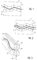
- la figure 1 est un mode de réalisation du procédé comportant une source émettrice unitaire ;
- la figure 2 est un mode de réalisation du procédé comportant une source émettrice dite double ;
- la figure 3 est une vue en perspective d'une source émettrice double ;
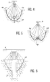
- la figure 4 est une vue en coupe en élévation frontale d'un réflecteur muni d'une source émettrice solidarisée par patte ;
- la figure 5 est une vue en coupe en élévation frontale d'un réflecteur muni d'une source émettrice solidarisée par encastrement partiel ;
- la figure 6 est une vue en coupe en élévation frontale d'un d'une source émettrice conformée en ruban, pouvant de même être encastré partiellement ;
- la figure 7 est une vue en perspective d'une source émettrice enrobée d'un conducteur thermique ;
- la figure 8 est une vue en perspective d'un tube pourvu d'ouvertures représentant directement la source ou l'enrobant en tant que diffuseur thermique ;
- Selon un mode préféré d'une installation pour la mise en oeuvre du procédé de chauffage par émission électromagnétique, elle comprend au moins une source rayonnante 1 ou émettrice constituée dans un matériau à fort pouvoir résistif et se présentant sous la forme d'un fil 2, d'un ruban 3 ou d'un tube 4 mais possédant quel que soit son mode de réalisation, des propriétés de malléabilité de manière à se conformer, par déformation plastique telle que notamment par pliage, par enroulement en spires, à la géométrie complexe des plans de joint 5, 6 des pièces 7, 8 thermoplastiques à assembler.
- La source émettrice, suivant différents modes d'obtention, peut éventuellement être laissée à l'air libre ou être insérée au sein d'un tube 4. Ce tube épouse de la même façon toutes les circonvolutions et les accidents de surface des lignes de joint ; en outre, il peut être étanche vis-à-vis du milieu extérieur et dans ce cas, la source émettrice baigne dans une atmosphère dépourvue ou remplie de gaz (halogéné, rare, inerte...), ou il autorise par l'intermédiaire d'une pluralité de mini buses réalisées par des ouvertures 9 pratiquées sur des lignes opposées de son volume en cas de source unique ou d'une seule ligne en cas de source dite double, une circulation et un soufflage directionnel de gaz chaud, provoquant ainsi des mouvements convectifs qui se combineront si besoin au transfert radiatif.
- Afin de permettre une focalisation du rayonnement sur les surfaces utiles et une non détérioration par ramollissement des zones extérieures dépourvues de cordon de joint, on pourvoit la source émettrice d'une surface réfléchissante 12 telle que notamment un réflecteur elliptique ou un miroir convexe du même type que les réflecteurs standards des lampes infrarouges mais de manière adaptée aux lignes tourmentées.
- L'efficacité de ce procédé est essentiellement liée à la conformation et la position relative du dispositif chauffant en regard des lignes de joint des pièces thermoplastiques. Afin de reproduire le plus fidèlement possible sa géométrie tridimensionnelle, on dispose sur l'ensemble des surfaces devant être chauffées, un cordon ou jonc 11 ( représenté en tirets sur la figure 3) en matériau souple, notamment du type élastomère à base de silicone, qui se conforme exactement au tracé des lignes de joint. Ce jonc 11 qui sera enlevé par la suite préfigure, en négatif, la partie réfléchissante 12 de la source rayonnante. Les pièces thermoplastiques pourvues au niveau de leur plan de joint respectif dudit cordon sont disposées sur la machine de production ou sur un gabarit d'usinage ; on rapproche les deux pièces d'une manière similaire à une opération de soudage fictive lorsque les pièces sont pratiquement en contact, on interpose entre elles et en regard d'un plan parallèle au cordon 11, une âme 13 rigide, notamment réalisée dans un matériau métallique servant d'armature et de squelette à une pluralité de couches 14, 15 en fibre et liant réfractaires qui emprisonnent, après solidification au niveau de leurs faces non liées à l'âme, les cordons en élastomère 11. Le sandwich ainsi formé résiste à la fois aux chocs mécaniques et thermiques importants, la partie centrale permet la fixation de la pluralité de sources émettrices 1 dans les zones creuses qui subsistent lors de l'enlèvement desdits cordons 11. Préalablement aux opérations de solidarisation des sources rayonnantes 1, on peut augmenter le pouvoir réfléchissant de ces zones creuses, en déposant par vaporisation un mince film 16 métallique à fort indice de réflexion tel que notamment un alliage métallique à base de nickel, d'argent, de cuivre. Cependant cet alliage jouira de propriétés de très faible conductivité thermique mais d'un excellent indice de réflexion et d'un point de fusion le plus élevé possible. A titre d'exemple, on cite un alliage de nickel et de cuivre, appelé communément "ARCAP" dont les caractéristiques sont les suivantes:
- couleur argent
- température de fusion : 1250 °C
- indice de réflexion optique 70 %
- conductivité thermique : 23 W / m °C
- anticorrosion à toute émanation gazeuse.
- On positionne au plus près du foyer des zones réfléchissantes 12, 16 ainsi élaborées une pluralité de sources rayonnantes 1 qui sont fixées de chaque côté du sandwich par des pattes 17, ou cheminent d'une manière semi-encastrée dans la couche réfractaire. Ladite source se présente sous la forme d'un filament 2 ou d'un ruban 3, de section droite circulaire ou rectangulaire constitués d'un métal offrant une très grande résistance au passage du courant qui induit donc un fort échauffement par effet Joule.
- On peut également, selon un autre mode de réalisation de la source émettrice 1, pratiquer une série d'usinages dans une matière notamment à base de résine polymère possédant des caractéristiques importantes de dureté et de résistance à l'échauffement. Les différentes phases de l'usinage sont mises en oeuvre à partir d'une machine éventuellement à commande numérique qui permet donc une conduite de l'outil de coupe tel que notamment une fraise dont les arêtes de coupe génèrent le profil de la zone réfléchissante 12 désiré de ladite source émettrice 1, en fonction des données CAO des pièces 7, 8 à assembler.
- L'empreinte ainsi obtenue élabore un moule, destiné à être rempli d'un alliage dont le point de fusion est compris dans la fourchette 50-200°C ; on citera pour exemple l'alliage de Bismuth (Température de fusion 137°C). Après solidification, on projette sur la surface libre de l'empreinte, un film 16 de faible épaisseur (0.5 mm) à base de Nickel. Ce film 16 présente des aspérités ou des rugosités pour un meilleur accrochage du matériau réfractaire qui sera rapporté ultérieurement. On pratique au sein de l'alliage solidifié une fente au niveau seulement des zones d'émission, pour la mise en place d'un ruban 3 ou d'un fil 2 résistifs.
- Compte tenu d'une continuité de la source émettrice et d'une discontinuité partielle de la zone émettrice définie par les pièces à assembler, les longueurs hors zone de travail seront noyées complètement au sein du matériau réfractaire rapporté ultérieurement, ce qui implique un changement de section important afin de garantir une baisse de la température du fil ou du ruban dans les zones hors réflecteur 12. Ces variations de section seront réalisées soit par diminution en usinant l'élément résistif, soit par augmentation en ajoutant de la matière par soudure classique sous gaz rare.
- Il convient dès à présent, d'une part, de solidariser la source émettrice à l'empreinte et, d'autre part, de permettre son intégration au sein de la machine de production, par un recouvrement ou une intégration dans une couche 14, 15 de matériau réfractaire dont la limite d'utilisation est au moins de 1400°C. La dernière opération consiste à placer le sandwich solidifié dans une ambiance dont la température est légèrement supérieure à la température de fusion de l'alliage (dans notre cas 150 °C). La fonte de métal laisse apparaître une surface réfléchissante 12 lisse, conforme au profil désiré de la source émettrice 1.
- Suivant les applications requises, c'est-à-dire en fonction de la quantité d'énergie devant être rayonnée par unité de longueur, ledit filament est enroulé en spirale, boudiné ou plié en accordéon dans le cas de ruban. Le conducteur électrique est notamment choisi parmi des filaments à base de tungstène, nickel, chrome, fer, aluminium tels que par exemple un fil résistif, connu sous le terme de "KANTHAL AF" (Fe Ni Cr) de diamètre 1 mm et boudiné sur un diamètre de 5 mm avec un pas de 2,5 mm. La puissance électrique appliquée sur ce conducteur et transformée par effet Joule en ondes électromagnétiques dans le spectre notamment de l'infrarouge, est de manière connue délivrée par des systèmes de puissance à base de relais statiques ou à thyristors.
- Selon un autre mode de réalisation de cette source rayonnante, elle est incluse dans un tube 4 à base de quartz et de silice ou elle est enrobée d'un matériau 19 à forte conductivité thermique, tel que notamment de la magnésie.
- Quel que soit le mode de réalisation, conducteur électrique à l'air libre, conducteur placé au sein d'un tube éventuellement percé, conducteur enrobé, ces derniers épousent parfaitement la géométrie tridimensionnelle des lignes de joint et ils sont positionnés au plus proche des foyers des zones réfléchissantes elliptiques de manière à focaliser les rayons incidents exclusivement vers les zones de joint.
- Lesdits conducteurs constituent une source unitaire rayonnant sur un angle solide de 360° sur une pluralité de lignes de joint appartenant à deux pièces distinctes, ou une source double séparée par une paroi absorbante diffusant chacune selon un angle solide d'environ 180° sur les lignes de joint respectives de chaque pièce thermoplastique.
- Le procédé de chauffage par émission infrarouge tel qu'il vient d'être décrit au sein de plusieurs modes de mise en oeuvre, autorise des mouvements et des cadences rapides de l'appareil de production, étant donné les faibles masses des sources émettrices et leur faible inertie tant mécanique que thermique ; par ailleurs, la focalisation très précise du rayonnement assure une fusion quasi instantanée des lignes de joint, et ce sans apport de matière extérieure. En outre, ce mode de fusion sans contact ne nécessite aucun arrêt de production pour le nettoyage des éléments chauffants.
- Il demeure bien entendu que la présente invention n'est pas limitée aux exemples de réalisation décrits et représentés ci-dessus, mais qu'elle en englobe toutes les variantes et notamment pour des applications de soudage de matières plastiques dans les domaines du jouet, de l'électroménager et de l'aéronautique.
Claims (11)
Applications Claiming Priority (2)
| Application Number | Priority Date | Filing Date | Title |
|---|---|---|---|
| FR9307333 | 1993-06-17 | ||
| FR9307333A FR2706353B1 (fr) | 1993-06-17 | 1993-06-17 | Procédé de chauffage par émission d'un rayonnement électromagnétique, notamment infrarouge. |
Publications (3)
| Publication Number | Publication Date |
|---|---|
| EP0629488A2 true EP0629488A2 (fr) | 1994-12-21 |
| EP0629488A3 EP0629488A3 (fr) | 1995-04-05 |
| EP0629488B1 EP0629488B1 (fr) | 1998-01-14 |
Family
ID=9448251
Family Applications (1)
| Application Number | Title | Priority Date | Filing Date |
|---|---|---|---|
| EP94401358A Expired - Lifetime EP0629488B1 (fr) | 1993-06-17 | 1994-06-16 | Procédé de chauffage par émission d'un rayonnement électromagnétique, notamment infrarouge |
Country Status (5)
| Country | Link |
|---|---|
| US (1) | US5628859A (fr) |
| EP (1) | EP0629488B1 (fr) |
| JP (1) | JPH079565A (fr) |
| DE (1) | DE69407871T2 (fr) |
| FR (1) | FR2706353B1 (fr) |
Cited By (3)
| Publication number | Priority date | Publication date | Assignee | Title |
|---|---|---|---|---|
| WO1995030534A1 (fr) * | 1994-05-10 | 1995-11-16 | Armin Dommer | Dispositif de soudage bout a bout de profiles en matiere plastique, notamment de tubes |
| WO2012065688A3 (fr) * | 2010-11-19 | 2012-07-26 | Heraeus Noblelight Gmbh | Dispositif d'irradiation |
| CN103912912A (zh) * | 2014-04-22 | 2014-07-09 | 张洪兴 | 管式红外线辐射采暖设备反射板的制造方法 |
Families Citing this family (24)
| Publication number | Priority date | Publication date | Assignee | Title |
|---|---|---|---|---|
| US20030185937A1 (en) * | 1997-03-13 | 2003-10-02 | Garwood Anthony J.M. | Tracking meat goods to country of origin |
| JPH1154496A (ja) * | 1997-08-07 | 1999-02-26 | Tokyo Electron Ltd | 熱処理装置及びガス処理装置 |
| US6054001A (en) * | 1998-02-17 | 2000-04-25 | Donnelly Corporation | Vehicle assembly line-side heat activation of a "ready-to-install" window fixing adhesive for attachment of a vehicle window to a vehicle |
| US6203639B1 (en) | 1998-02-17 | 2001-03-20 | Donnelly Corporation | Vehicle assembly line-side heat activation of a “ready-to-install” window fixing adhesive for attachment of a vehicle window to a vehicle |
| US6041164A (en) * | 1998-11-04 | 2000-03-21 | Hofius, Sr.; David V. | Expansion and mounting apparatus for infrared radiant energy source |
| CN1138452C (zh) * | 1999-11-30 | 2004-02-11 | 松下电器产业株式会社 | 红外线灯、加热装置和生产红外线灯的方法 |
| US20030221783A1 (en) * | 2000-05-10 | 2003-12-04 | Swagelok Company | Ir welding of fluoropolymers |
| PT1280653E (pt) * | 2000-05-10 | 2005-02-28 | Swagelok Co | Dispositivo de segurar e posicionar para soldadura de iv |
| FR2818926B1 (fr) * | 2000-12-28 | 2003-04-04 | Mecaplast Sam | Dispositif de soudage de pieces en matiere thermoplastique par rayonnement electromagnetique notamment infrarouge |
| US7118780B2 (en) * | 2001-03-16 | 2006-10-10 | Semiconductor Energy Laboratory Co., Ltd. | Heat treatment method |
| US6793120B2 (en) | 2002-01-17 | 2004-09-21 | Donnelly Corporation | Apparatus and method for mounting an electrical connector to a glass sheet of a vehicle window |
| US7063183B2 (en) * | 2002-10-29 | 2006-06-20 | Collins & Aikman Products Co. | Apparatus and methods of forming sound attenuating laminates having fiber and mass layers |
| TWI361814B (en) * | 2003-03-07 | 2012-04-11 | Kuraray Co | Plastic bonding method |
| JP2004345094A (ja) * | 2003-05-20 | 2004-12-09 | Koito Mfg Co Ltd | 車両用灯具の製造装置 |
| DE10341503A1 (de) * | 2003-09-05 | 2005-03-31 | Patent-Treuhand-Gesellschaft für elektrische Glühlampen mbH | Infrarotreflektor und Infrarotstrahler mit einem derartigen Infrarotreflektor |
| JP4294445B2 (ja) * | 2003-11-07 | 2009-07-15 | パナソニック株式会社 | 赤外線電球、加熱装置、及び赤外線電球の製造方法 |
| CN100520217C (zh) * | 2004-02-05 | 2009-07-29 | 环球拔萃有限公司 | 放射仪器 |
| DE102005034627A1 (de) * | 2005-07-19 | 2007-02-01 | Takata-Petri Ag | Vorrichtung und Verfahren zum Entfernen eines längs erstreckten Grates an einem Formteil |
| EP2842723B1 (fr) | 2006-03-23 | 2019-08-14 | HELLA GmbH & Co. KGaA | Dispositif destiné à chauffer des emplacements de liaison |
| DE102006034173A1 (de) * | 2006-07-24 | 2008-01-31 | Siemens Ag | Vorrichtung zum Fügen von Teilen aus thermoplastischem Kunststoff |
| CN103223725A (zh) * | 2012-10-08 | 2013-07-31 | 李文忠 | 柔性高频电磁脉冲功率发射带 |
| US10718527B2 (en) * | 2016-01-06 | 2020-07-21 | James William Masten, JR. | Infrared radiant emitter |
| CN108235477A (zh) * | 2018-03-14 | 2018-06-29 | 宁波萨科森工业科技有限公司 | 一种卡口加热器 |
| US12350890B2 (en) * | 2020-12-28 | 2025-07-08 | Mitsubishi Heavy Industries, Ltd. | Composite material bonding apparatus and composite material bonding method |
Family Cites Families (21)
| Publication number | Priority date | Publication date | Assignee | Title |
|---|---|---|---|---|
| US2705523A (en) * | 1951-06-29 | 1955-04-05 | Goodrich Co B F | Heat-seaming apparatus for thermoplastic sheet materials |
| US3131623A (en) * | 1961-10-30 | 1964-05-05 | Phillips Petroleum Co | Method and apparatus for making thermoplastic film seams |
| FR1319307A (fr) * | 1961-12-05 | 1963-03-01 | Procédé de soudure des matières thermoplastiques par système optique | |
| US3472721A (en) * | 1966-01-24 | 1969-10-14 | Research Inc | Apparatus for lap joinder of plastic sheets |
| DE1942047A1 (de) * | 1969-08-19 | 1971-03-18 | Eugen G Henkel Maschinenfabrik | Zwickmaschine fuer die Verarbeitung von Brandsohlen mit aktivierbarer Klebstoffschicht |
| US3694289A (en) * | 1970-06-22 | 1972-09-26 | Continental Can Co | Apparatus for making heat sealed tubes |
| FR2176558B1 (fr) * | 1972-03-23 | 1974-08-30 | Tuboplast France | |
| US3804691A (en) * | 1972-05-12 | 1974-04-16 | Western Electric Co | Method of bonding using an infrared heating lamp |
| DE2520217C2 (de) * | 1975-05-07 | 1985-01-31 | Schlegel Lining Technology GmbH, 2000 Hamburg | Verfahren und Vorrichtung zum kontinuierlichen Verschweißen von großflächigen thermoplastischen Kunststoffolien oder -tafeln |
| US3956053A (en) * | 1974-10-15 | 1976-05-11 | General Binding Corporation | Apparatus and method for binding with adhesive covers |
| DD144656A1 (de) * | 1979-06-29 | 1980-10-29 | Wolfgang Tobias | Heizelement-schweisswerkzeug zum stumpfschweissen thermoplastischer halbzeuge |
| JPS60184829A (ja) * | 1984-03-05 | 1985-09-20 | Nippon Denso Co Ltd | 熱可塑性樹脂部材の熱輻射溶接方法 |
| DE3408901A1 (de) * | 1984-03-10 | 1985-09-19 | Optima-Maschinenfabrik Dr. Bühler GmbH & Co, 7170 Schwäbisch Hall | Vorrichtung zum schweissen von folien |
| EP0335951A1 (fr) * | 1987-10-19 | 1989-10-11 | Vinidex Tubemakers Pty. Ltd. | Agencement pour le soudage de feuilles thermoplastiques |
| GB8803923D0 (en) * | 1988-02-19 | 1988-03-23 | Gen Electric Co Plc | Optical storage devices |
| JPH01229616A (ja) * | 1988-03-11 | 1989-09-13 | Kobayashi Kogyo Kk | 合成樹脂製成形品の熱溶着方法 |
| US5151149A (en) * | 1988-07-28 | 1992-09-29 | The Entwistle Corporation | Apparatus for bonding or melt fusing plastic and plastic matrix composite materials |
| EP0427793A4 (en) * | 1988-07-28 | 1992-01-15 | Henry D. Swartz | Bonding of plastic and plastic matrix composite materials |
| DE3919800A1 (de) * | 1989-06-16 | 1990-12-20 | Branson Ultraschall | Schweissmaschine mit schweissspiegel |
| US5035045A (en) * | 1990-09-10 | 1991-07-30 | Globe-Union Inc. | Method of joining bipolar battery frames |
| DE9218016U1 (de) * | 1992-12-17 | 1993-08-19 | Branson Ultraschall Niederlassung Der Emerson Technologies Gmbh & Co, 63128 Dietzenbach | Vorrichtung zum Erwärmen und Aufschmelzen von Kunststoffen |
-
1993
- 1993-06-17 FR FR9307333A patent/FR2706353B1/fr not_active Expired - Fee Related
-
1994
- 1994-06-03 US US08/253,343 patent/US5628859A/en not_active Expired - Lifetime
- 1994-06-14 JP JP6131761A patent/JPH079565A/ja active Pending
- 1994-06-16 DE DE69407871T patent/DE69407871T2/de not_active Expired - Fee Related
- 1994-06-16 EP EP94401358A patent/EP0629488B1/fr not_active Expired - Lifetime
Cited By (7)
| Publication number | Priority date | Publication date | Assignee | Title |
|---|---|---|---|---|
| WO1995030534A1 (fr) * | 1994-05-10 | 1995-11-16 | Armin Dommer | Dispositif de soudage bout a bout de profiles en matiere plastique, notamment de tubes |
| WO2012065688A3 (fr) * | 2010-11-19 | 2012-07-26 | Heraeus Noblelight Gmbh | Dispositif d'irradiation |
| CN103282999A (zh) * | 2010-11-19 | 2013-09-04 | 贺利氏特种光源有限责任公司 | 辐射装置 |
| US8785894B2 (en) | 2010-11-19 | 2014-07-22 | Heraeus Noblelight Gmbh | Irradiation device having transition glass seal |
| CN103282999B (zh) * | 2010-11-19 | 2016-06-29 | 贺利氏特种光源有限责任公司 | 辐射装置 |
| CN103912912A (zh) * | 2014-04-22 | 2014-07-09 | 张洪兴 | 管式红外线辐射采暖设备反射板的制造方法 |
| CN103912912B (zh) * | 2014-04-22 | 2016-05-18 | 张洪兴 | 管式红外线辐射采暖设备反射板的制造方法 |
Also Published As
| Publication number | Publication date |
|---|---|
| FR2706353B1 (fr) | 1996-01-26 |
| DE69407871T2 (de) | 1998-07-16 |
| EP0629488A3 (fr) | 1995-04-05 |
| FR2706353A1 (fr) | 1994-12-23 |
| JPH079565A (ja) | 1995-01-13 |
| EP0629488B1 (fr) | 1998-01-14 |
| US5628859A (en) | 1997-05-13 |
| DE69407871D1 (de) | 1998-02-19 |
Similar Documents
| Publication | Publication Date | Title |
|---|---|---|
| EP0629488B1 (fr) | Procédé de chauffage par émission d'un rayonnement électromagnétique, notamment infrarouge | |
| US7244051B2 (en) | Light-generating apparatus having a reflector | |
| JP5792720B2 (ja) | イメージングアセンブリ | |
| US7210833B2 (en) | Method of fixing a power light-emitting diode on a radiator, and a signalling device comprising such a diode | |
| JP4435352B2 (ja) | 熱溶融性合成樹脂の溶着方法 | |
| FR2670562A1 (fr) | Dispositif d'eclairage pour vehicules. | |
| CA2218414C (fr) | Procede et dispositif de chauffage selectif d'une preforme de recipient | |
| FR2606125A1 (fr) | Projecteur perfectionne pour vehicule automobile | |
| US4342142A (en) | Method for manufacturing sealed-beam type electric bulb | |
| JP2004195552A (ja) | レーザー溶接用レンズ組立部品 | |
| US6911108B2 (en) | Photon welding devices for joining plastic parts | |
| HU211010B (en) | Method of forming weld for connecting polyolefinic pipes | |
| US2543093A (en) | Electric lamp | |
| FR2487040A1 (fr) | Projecteur d'eclairage notamment pour vehicules automobiles | |
| US8866051B2 (en) | Apparatus and method for applying a protective element on an optical waveguide | |
| EP1652214B1 (fr) | Lampe electrique | |
| FR2484058A1 (fr) | Bloc optique d'eclairage, notamment pour projecteur de vehicule automobile | |
| EP1219407B1 (fr) | Dispositif de soudage de pièces en matière thermoplastique par rayonnement électromagnétique notamment infrarouge | |
| CA2457743C (fr) | Methode et appareil de soudage infrarouge de pieces thermoplastiques | |
| JPH10166453A (ja) | プラスチックの融着装置 | |
| FR2738622A1 (fr) | Ensemble d'eclairage par source de lumiere deportee, equipe d'une chicane thermique, et candelabre incorporant un tel ensemble d'eclairage | |
| JPS5856205B2 (ja) | リ−ドスイツチのガラス管封止装置 | |
| FR3097465A1 (fr) | Elément de support avec portion d’isolation thermique | |
| FR2685250A1 (fr) | Procede d'incorporation d'un element de rechauffage dans une structure en materiau composite. | |
| JP2019119144A (ja) | Pd(pdocj)方式およびpd継手ならびにpd部品に関する一群の追加6 加熱用被覆pd線について |
Legal Events
| Date | Code | Title | Description |
|---|---|---|---|
| PUAI | Public reference made under article 153(3) epc to a published international application that has entered the european phase |
Free format text: ORIGINAL CODE: 0009012 |
|
| AK | Designated contracting states |
Kind code of ref document: A2 Designated state(s): DE ES GB IT |
|
| PUAL | Search report despatched |
Free format text: ORIGINAL CODE: 0009013 |
|
| AK | Designated contracting states |
Kind code of ref document: A3 Designated state(s): DE ES GB IT |
|
| 17P | Request for examination filed |
Effective date: 19950421 |
|
| 17Q | First examination report despatched |
Effective date: 19960507 |
|
| RAP1 | Party data changed (applicant data changed or rights of an application transferred) |
Owner name: FORWARD TECHNOLOGY INDUSTRIES |
|
| GRAG | Despatch of communication of intention to grant |
Free format text: ORIGINAL CODE: EPIDOS AGRA |
|
| GRAG | Despatch of communication of intention to grant |
Free format text: ORIGINAL CODE: EPIDOS AGRA |
|
| GRAH | Despatch of communication of intention to grant a patent |
Free format text: ORIGINAL CODE: EPIDOS IGRA |
|
| GRAH | Despatch of communication of intention to grant a patent |
Free format text: ORIGINAL CODE: EPIDOS IGRA |
|
| GRAA | (expected) grant |
Free format text: ORIGINAL CODE: 0009210 |
|
| ITF | It: translation for a ep patent filed | ||
| AK | Designated contracting states |
Kind code of ref document: B1 Designated state(s): DE ES GB IT |
|
| PG25 | Lapsed in a contracting state [announced via postgrant information from national office to epo] |
Ref country code: ES Free format text: THE PATENT HAS BEEN ANNULLED BY A DECISION OF A NATIONAL AUTHORITY Effective date: 19980114 |
|
| GBT | Gb: translation of ep patent filed (gb section 77(6)(a)/1977) |
Effective date: 19980116 |
|
| REF | Corresponds to: |
Ref document number: 69407871 Country of ref document: DE Date of ref document: 19980219 |
|
| PLBE | No opposition filed within time limit |
Free format text: ORIGINAL CODE: 0009261 |
|
| STAA | Information on the status of an ep patent application or granted ep patent |
Free format text: STATUS: NO OPPOSITION FILED WITHIN TIME LIMIT |
|
| 26N | No opposition filed | ||
| REG | Reference to a national code |
Ref country code: GB Ref legal event code: IF02 |
|
| PGFP | Annual fee paid to national office [announced via postgrant information from national office to epo] |
Ref country code: IT Payment date: 20090623 Year of fee payment: 16 |
|
| PGFP | Annual fee paid to national office [announced via postgrant information from national office to epo] |
Ref country code: GB Payment date: 20090618 Year of fee payment: 16 Ref country code: DE Payment date: 20090622 Year of fee payment: 16 |
|
| GBPC | Gb: european patent ceased through non-payment of renewal fee |
Effective date: 20100616 |
|
| PG25 | Lapsed in a contracting state [announced via postgrant information from national office to epo] |
Ref country code: IT Free format text: LAPSE BECAUSE OF NON-PAYMENT OF DUE FEES Effective date: 20100616 |
|
| PG25 | Lapsed in a contracting state [announced via postgrant information from national office to epo] |
Ref country code: DE Free format text: LAPSE BECAUSE OF NON-PAYMENT OF DUE FEES Effective date: 20110101 |
|
| PG25 | Lapsed in a contracting state [announced via postgrant information from national office to epo] |
Ref country code: GB Free format text: LAPSE BECAUSE OF NON-PAYMENT OF DUE FEES Effective date: 20100616 |