EP0629533B1 - Procédé d'operation d'un système de freinage pour véhicule - Google Patents
Procédé d'operation d'un système de freinage pour véhicule Download PDFInfo
- Publication number
- EP0629533B1 EP0629533B1 EP94107084A EP94107084A EP0629533B1 EP 0629533 B1 EP0629533 B1 EP 0629533B1 EP 94107084 A EP94107084 A EP 94107084A EP 94107084 A EP94107084 A EP 94107084A EP 0629533 B1 EP0629533 B1 EP 0629533B1
- Authority
- EP
- European Patent Office
- Prior art keywords
- brake
- pressure
- vehicle
- takes place
- change
- Prior art date
- Legal status (The legal status is an assumption and is not a legal conclusion. Google has not performed a legal analysis and makes no representation as to the accuracy of the status listed.)
- Expired - Lifetime
Links
- 238000000034 method Methods 0.000 title claims 7
- 230000001419 dependent effect Effects 0.000 claims description 2
- 230000004913 activation Effects 0.000 claims 1
- 238000001208 nuclear magnetic resonance pulse sequence Methods 0.000 claims 1
- 230000000630 rising effect Effects 0.000 claims 1
- 238000010586 diagram Methods 0.000 description 4
- 230000006978 adaptation Effects 0.000 description 3
- 230000003068 static effect Effects 0.000 description 2
- 230000002123 temporal effect Effects 0.000 description 2
- 230000036461 convulsion Effects 0.000 description 1
- 230000000694 effects Effects 0.000 description 1
- 230000006870 function Effects 0.000 description 1
- 230000005484 gravity Effects 0.000 description 1
- 230000004048 modification Effects 0.000 description 1
- 238000012986 modification Methods 0.000 description 1
- 230000000717 retained effect Effects 0.000 description 1
Images
Classifications
-
- B—PERFORMING OPERATIONS; TRANSPORTING
- B60—VEHICLES IN GENERAL
- B60T—VEHICLE BRAKE CONTROL SYSTEMS OR PARTS THEREOF; BRAKE CONTROL SYSTEMS OR PARTS THEREOF, IN GENERAL; ARRANGEMENT OF BRAKING ELEMENTS ON VEHICLES IN GENERAL; PORTABLE DEVICES FOR PREVENTING UNWANTED MOVEMENT OF VEHICLES; VEHICLE MODIFICATIONS TO FACILITATE COOLING OF BRAKES
- B60T8/00—Arrangements for adjusting wheel-braking force to meet varying vehicular or ground-surface conditions, e.g. limiting or varying distribution of braking force
- B60T8/26—Arrangements for adjusting wheel-braking force to meet varying vehicular or ground-surface conditions, e.g. limiting or varying distribution of braking force characterised by producing differential braking between front and rear wheels
- B60T8/266—Arrangements for adjusting wheel-braking force to meet varying vehicular or ground-surface conditions, e.g. limiting or varying distribution of braking force characterised by producing differential braking between front and rear wheels using valves or actuators with external control means
-
- B—PERFORMING OPERATIONS; TRANSPORTING
- B60—VEHICLES IN GENERAL
- B60T—VEHICLE BRAKE CONTROL SYSTEMS OR PARTS THEREOF; BRAKE CONTROL SYSTEMS OR PARTS THEREOF, IN GENERAL; ARRANGEMENT OF BRAKING ELEMENTS ON VEHICLES IN GENERAL; PORTABLE DEVICES FOR PREVENTING UNWANTED MOVEMENT OF VEHICLES; VEHICLE MODIFICATIONS TO FACILITATE COOLING OF BRAKES
- B60T8/00—Arrangements for adjusting wheel-braking force to meet varying vehicular or ground-surface conditions, e.g. limiting or varying distribution of braking force
- B60T8/32—Arrangements for adjusting wheel-braking force to meet varying vehicular or ground-surface conditions, e.g. limiting or varying distribution of braking force responsive to a speed condition, e.g. acceleration or deceleration
- B60T8/34—Arrangements for adjusting wheel-braking force to meet varying vehicular or ground-surface conditions, e.g. limiting or varying distribution of braking force responsive to a speed condition, e.g. acceleration or deceleration having a fluid pressure regulator responsive to a speed condition
- B60T8/50—Arrangements for adjusting wheel-braking force to meet varying vehicular or ground-surface conditions, e.g. limiting or varying distribution of braking force responsive to a speed condition, e.g. acceleration or deceleration having a fluid pressure regulator responsive to a speed condition having means for controlling the rate at which pressure is reapplied to or released from the brake
Definitions
- a brake system for motor vehicles, in particular commercial vehicles, with the features of the preamble of claim 1 is known from DE 34 16 979 A1.
- the required brake jerk distribution for the brake cylinders generating the clamping force can be determined with additional brake data.
- a brake pressure control device for optimizing wear between the brakes of commercial vehicles is known from EP 561 049 A1, which has not been previously published. Pressure is retained on the brakes with greater wear, which is superimposed on the load-dependent control of the brake pressure. Influencing the time gradient of the pressure rise is not described.
- the aim of the invention is to avoid this possible instability in the control phase. It is achieved by adapting the temporal pressure gradient of the rear axle to the load according to claim 1.
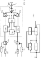
- FIG. 1 shows a block diagram of a brake system according to the invention
- FIG. 2 shows a block diagram of a control model
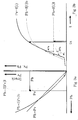
- FIG. 3 shows diagrams for explaining the invention.
- a command variable is transmitted from the brake value transmitter 1 to the central electronics 2.
- a setpoint is determined from this in a block 21.
- vehicle-specific data for determining the brake pressure distribution, key data for the center of gravity and brake ratios one supplied via a terminal 23 by a sensor (not shown) (e.g. pressure in the air bellows)
- Signal indicating the loading state which, however, can also be entered via a data bus, as described below, and the setpoint from block 21, pressure blocks for the brakes of the front and rear axles are determined in blocks 24a and 24b.
- These signals contain both the level of the pressure to be controlled on the individual axes and information about the gradient with which the target pressure is to be controlled. These signals go to control blocks 25a and 25b, which control pressure control modules 3a and 3b, which in turn control pressure from reservoirs 4a and 4b on brake cylinders 5a and 5b. A timing is carried out via a block 26.
- the embodiment of Figure 1 can e.g. the controller model of Figure 2 is based. There the pressure control module, the line and the brake cylinder are combined in a block 7. An identification block 8 reports identification data to a block 9, which adapts (modifies) the controller 2 when the identification data changes.
- Control and feedback signals lead to a "route" identification, which describes the behavior of the pressure control module, the brake line and the brake cylinder and leads to modification parameters of the "controller".
- Various sensors can also be connected to the pressure control modules 3a and 3b, the data for further processing via the Data bus are given to the central control unit. It is not necessary that all sensors are connected. In some cases, data can be roughly determined indirectly by comparison or interim calculations.
- p h means the rear axle brake pressure
- p v the front axle brake pressure.
- p H p v drawn.
- the corresponding pressure distribution curve should be effective for the pressure distribution. They are stored in block 22. Further intermediate distribution curves for the partially loaded vehicle can also be stored in block 22 or calculated. The curve to be used is selected based on the load signal at terminal 23.
- the pressure build-up on the front axle p v f (t) carried out at the same speed for the loaded and empty vehicle (solid line).
- the course of the invention for the empty vehicle is shown dotted.
- the aim of the electric brake is actually to quickly adjust the pressure so that the command variable desired by the driver can be achieved with little time delay.
- the timing of the rear axle will first reach its target pressure p h if the vehicle is empty, for example, if the pressure builds up just as quickly as that of the loaded vehicle (thin line). After sufficient energy has also flowed into the front brake cylinder, it will have the desired pressure p v with a time delay.
- reaching p h at an early stage is equivalent to the fact that the rear axle takes a higher amount of force than the front axle for a short time. This can easily lead to instability of the vehicle.
- the invention pressure gradient adaptation ensures that both pressure control loops achieve the optimal pressure distribution at about the same time at t x .
- the invention can be used in brake systems (compressed air, vacuum, hydraulics, electrics) with electronic data processing.
- the pressure gradients can be adjusted as a function of the vehicle mass or one or more wheel or axle loads. A presetting can be made based on static vehicle and brake data.
- the pressure gradient can be optimized with dynamic vehicle and brake data.
- the pressure gradients can also be adjusted by indirectly determining the loading via deceleration and Wheel speed differences occur.
- the metering of the flow rate at the pressure control module takes place according to the aforementioned criteria by pulse-width-modulated control of valves, or control of a flow cross-section, or force-controlled metering devices.
Landscapes
- Engineering & Computer Science (AREA)
- Transportation (AREA)
- Mechanical Engineering (AREA)
- Physics & Mathematics (AREA)
- Fluid Mechanics (AREA)
- Hydraulic Control Valves For Brake Systems (AREA)
- Regulating Braking Force (AREA)
Claims (6)
- Procédé pour faire fonctionner une installation de freinage, dans laquelle on convertit un signal de freinage produit par le conducteur en signaux de commande d'une pression de freinage de consigne différente pour les roues des essieux, ces signaux de commande de la pression de freinage de consigne étant fonction de la charge et dans le cas de laquelle on applique avec ces signaux de commande de pression de freinage de consigne les pressions correspondantes de freinage sur les freins,
caractérisé en ce que
le gradient dans le temps de l'augmentation de la pression (Δp / Δt) peut être influencé pour l'essieu arrière et être modifié en fonction du chargement, la pression de freinage sur l'essieu arrière croissant plus lentement dans le cas d'un chargement plus faible que dans le cas d'un chargement plus grand. - Procédé selon la revendication 1,
caractérisé en ce que
la variation du gradient a lieu en faisant varier la largeur d'impulsion et/ou la fréquence d'une suite d'impulsions de commande pour une vanne d'alimentation. - Procédé selon la revendication 1,
caractérisé en ce que
la variation du gradient a lieu en faisant varier la section transversale d'écoulement. - Procédé selon la revendication 1,
caractérisé en ce que
la variation du gradient a lieu au moyen d'un dispositif de dosage commandé par une force. - Procédé selon l'une des revendications 1 à 4,
caractérisé en ce que
la variation des gradients a lieu en fonction d'une ou plusieurs charges de roue ou d'essieu. - Procédé selon l'une des revendications 1 à 4,
caractérisé en ce que
la variation du gradient a lieu en fonction de données dynamiques du véhicule et/ou des freins.
Applications Claiming Priority (2)
| Application Number | Priority Date | Filing Date | Title |
|---|---|---|---|
| DE4319509A DE4319509A1 (de) | 1993-06-12 | 1993-06-12 | Bremsanlage für ein Kraftfahrzeug |
| DE4319509 | 1993-06-12 |
Publications (3)
| Publication Number | Publication Date |
|---|---|
| EP0629533A1 EP0629533A1 (fr) | 1994-12-21 |
| EP0629533B1 true EP0629533B1 (fr) | 1997-08-27 |
| EP0629533B2 EP0629533B2 (fr) | 2000-08-23 |
Family
ID=6490207
Family Applications (1)
| Application Number | Title | Priority Date | Filing Date |
|---|---|---|---|
| EP94107084A Expired - Lifetime EP0629533B2 (fr) | 1993-06-12 | 1994-05-06 | Procédé d'operation d'un système de freinage pour véhicule |
Country Status (3)
| Country | Link |
|---|---|
| EP (1) | EP0629533B2 (fr) |
| JP (1) | JPH079967A (fr) |
| DE (2) | DE4319509A1 (fr) |
Families Citing this family (4)
| Publication number | Priority date | Publication date | Assignee | Title |
|---|---|---|---|---|
| DE4320904C2 (de) * | 1993-06-24 | 2002-11-14 | Bosch Gmbh Robert | Antiblockierregelsystem |
| US5941608A (en) | 1996-03-07 | 1999-08-24 | Kelsey-Hayes Company | Electronic brake management system with manual fail safe |
| GB2367868A (en) * | 2000-10-14 | 2002-04-17 | Trw Ltd | Delayed rear brake application in electro-hydraulic (EHB) braking systems |
| US6860569B1 (en) | 2002-05-23 | 2005-03-01 | Kelsey-Hayes Company | Electro-hydraulic brake system with four wheel push through |
Family Cites Families (6)
| Publication number | Priority date | Publication date | Assignee | Title |
|---|---|---|---|---|
| DE3432841A1 (de) † | 1984-09-07 | 1986-03-20 | Robert Bosch Gmbh, 7000 Stuttgart | Bremskraftregelanlage |
| DE3742435A1 (de) † | 1987-12-15 | 1989-07-06 | Opel Adam Ag | Hydraulische fahrzeugbremsanlage |
| JPH02128951A (ja) * | 1988-11-10 | 1990-05-17 | Nippon Denso Co Ltd | ブレーキ装置 |
| DE3901923A1 (de) * | 1989-01-24 | 1990-09-13 | Bosch Gmbh Robert | Elektronisch gesteuerter bremskraftverteiler |
| EP0569599A1 (fr) * | 1991-12-02 | 1993-11-18 | Nisshinbo Industries, Inc. | Soupape hydraulique de freins, dispositif et procede de commande |
| DE4209178A1 (de) * | 1992-03-20 | 1993-09-23 | Knorr Bremse Ag | Bremsdruckregeleinrichtung zur verschleissoptimierung zwischen bremsen von nutzfahrzeugen |
-
1993
- 1993-06-12 DE DE4319509A patent/DE4319509A1/de not_active Withdrawn
-
1994
- 1994-05-06 EP EP94107084A patent/EP0629533B2/fr not_active Expired - Lifetime
- 1994-05-06 DE DE59403839T patent/DE59403839D1/de not_active Expired - Lifetime
- 1994-05-16 JP JP6101092A patent/JPH079967A/ja active Pending
Also Published As
| Publication number | Publication date |
|---|---|
| DE4319509A1 (de) | 1994-12-15 |
| DE59403839D1 (de) | 1997-10-02 |
| EP0629533B2 (fr) | 2000-08-23 |
| JPH079967A (ja) | 1995-01-13 |
| EP0629533A1 (fr) | 1994-12-21 |
Similar Documents
| Publication | Publication Date | Title |
|---|---|---|
| EP0481043B1 (fr) | Systeme de regulateurs connectes entre eux-memes pour vehicules a moteur | |
| DE4225983C2 (de) | Verfahren zur Bremsung von Fahrzeugrädern | |
| DE4438252C2 (de) | Verfahren und Vorrichtung zur elektronischen Steuerung der Bremsanlage eines Fahrzeugs | |
| EP1414684B1 (fr) | Systeme de freinage pour remorques de vehicules utilitaires | |
| EP0445575A2 (fr) | Procédé de répartition de pression de freinage entre les axes d'un véhicule automobile muni d'un frein à fluide sous pression à anti-blocage | |
| EP0885793B1 (fr) | Procédé de freinage d'un véhicule | |
| DE19616732B4 (de) | Verfahren und Vorrichtung zur Steuerung der Bremsanlage eines Fahrzeugs | |
| EP0949130B2 (fr) | Dispositif de commande d'un système de freinage de véhicule | |
| EP0405114B1 (fr) | Installation de freinage commandée par fluide sous pression pour véhicules multiessieux | |
| EP0173954A2 (fr) | Procédé de réglage de la puissance de freinage | |
| EP1530529A1 (fr) | Module regulateur de pression pour un systeme de freinage pneumatique d'un vehicule | |
| DE3733801A1 (de) | Antiblockiersystem fuer fahrzeuge | |
| DE19501286B4 (de) | Verfahren und Vorrichtung zur Steuerung einer Bremsanlage eines Fahrzeugs | |
| DE19733379A1 (de) | Verfahren und Vorrichtung zur Steuerung einer Bremsanlage | |
| DE19854788B4 (de) | Radmodul für ein Fahrzeug | |
| EP0629533B1 (fr) | Procédé d'operation d'un système de freinage pour véhicule | |
| EP0956983B1 (fr) | Dispositif de commande de fonctions d'un véhicule | |
| DE19749015A1 (de) | Verfahren zur Abstimmung von Bremskräften zwischen jeweils zwei miteinander verbundenen Teilen einer Fahrzeugeinheit | |
| EP2213535B1 (fr) | Procédé de réglage ABS pour un véhicule et véhicule doté d'un système de freinage ABS | |
| EP0901949B1 (fr) | Procédé de freinage d'un véhicule | |
| DE102023136213A1 (de) | Verfahren zum Betreiben eines Antiblockiersystems eines Fahrzeugs, insbesondere Nutzfahrzeugs, Computerprogramm und/oder computerlesbares Medium, Steuergerät und Fahrzeug, insbesondere Nutzfahrzeug | |
| EP4705163A1 (fr) | Procédé de fonctionnement d'un système de freinage antiblocage d'un véhicule, en particulier d'un véhicule utilitaire, programme informatique et/ou support lisible par ordinateur, dispositif de commande et véhicule, en particulier véhicule utilitaire | |
| DE29924977U1 (de) | Einrichtung zur Steuerung von Betriebsfunktionen eines Fahrzeuges | |
| EP0835772A2 (fr) | Commande pour les amortisseurs d'une suspension |
Legal Events
| Date | Code | Title | Description |
|---|---|---|---|
| PUAI | Public reference made under article 153(3) epc to a published international application that has entered the european phase |
Free format text: ORIGINAL CODE: 0009012 |
|
| AK | Designated contracting states |
Kind code of ref document: A1 Designated state(s): DE FR GB IE |
|
| 17P | Request for examination filed |
Effective date: 19950621 |
|
| 17Q | First examination report despatched |
Effective date: 19960226 |
|
| GRAG | Despatch of communication of intention to grant |
Free format text: ORIGINAL CODE: EPIDOS AGRA |
|
| GRAH | Despatch of communication of intention to grant a patent |
Free format text: ORIGINAL CODE: EPIDOS IGRA |
|
| EN | Fr: translation not filed | ||
| GRAH | Despatch of communication of intention to grant a patent |
Free format text: ORIGINAL CODE: EPIDOS IGRA |
|
| GRAA | (expected) grant |
Free format text: ORIGINAL CODE: 0009210 |
|
| AK | Designated contracting states |
Kind code of ref document: B1 Designated state(s): DE FR GB IE |
|
| ET | Fr: translation filed | ||
| REF | Corresponds to: |
Ref document number: 59403839 Country of ref document: DE Date of ref document: 19971002 |
|
| GBT | Gb: translation of ep patent filed (gb section 77(6)(a)/1977) |
Effective date: 19971031 |
|
| PLBQ | Unpublished change to opponent data |
Free format text: ORIGINAL CODE: EPIDOS OPPO |
|
| PLBI | Opposition filed |
Free format text: ORIGINAL CODE: 0009260 |
|
| PG25 | Lapsed in a contracting state [announced via postgrant information from national office to epo] |
Ref country code: IE Free format text: LAPSE BECAUSE OF NON-PAYMENT OF DUE FEES Effective date: 19980605 |
|
| PLBF | Reply of patent proprietor to notice(s) of opposition |
Free format text: ORIGINAL CODE: EPIDOS OBSO |
|
| REG | Reference to a national code |
Ref country code: IE Ref legal event code: FD4D Ref document number: 76048 Country of ref document: IE |
|
| 26 | Opposition filed |
Opponent name: DAIMLER-BENZ AKTIENGESELLSCHAFT Effective date: 19980512 |
|
| PLBF | Reply of patent proprietor to notice(s) of opposition |
Free format text: ORIGINAL CODE: EPIDOS OBSO |
|
| PLAB | Opposition data, opponent's data or that of the opponent's representative modified |
Free format text: ORIGINAL CODE: 0009299OPPO |
|
| R26 | Opposition filed (corrected) |
Opponent name: DAIMLERCHRYSLER AG Effective date: 19980512 |
|
| PLBQ | Unpublished change to opponent data |
Free format text: ORIGINAL CODE: EPIDOS OPPO |
|
| PLAB | Opposition data, opponent's data or that of the opponent's representative modified |
Free format text: ORIGINAL CODE: 0009299OPPO |
|
| R26 | Opposition filed (corrected) |
Opponent name: DAIMLERCHRYSLER AG Effective date: 19980512 |
|
| PLAW | Interlocutory decision in opposition |
Free format text: ORIGINAL CODE: EPIDOS IDOP |
|
| PLAW | Interlocutory decision in opposition |
Free format text: ORIGINAL CODE: EPIDOS IDOP |
|
| PUAH | Patent maintained in amended form |
Free format text: ORIGINAL CODE: 0009272 |
|
| STAA | Information on the status of an ep patent application or granted ep patent |
Free format text: STATUS: PATENT MAINTAINED AS AMENDED |
|
| 27A | Patent maintained in amended form |
Effective date: 20000823 |
|
| AK | Designated contracting states |
Kind code of ref document: B2 Designated state(s): DE FR GB IE |
|
| ET3 | Fr: translation filed ** decision concerning opposition | ||
| GBTA | Gb: translation of amended ep patent filed (gb section 77(6)(b)/1977) | ||
| REG | Reference to a national code |
Ref country code: GB Ref legal event code: IF02 |
|
| PGFP | Annual fee paid to national office [announced via postgrant information from national office to epo] |
Ref country code: GB Payment date: 20040423 Year of fee payment: 11 |
|
| PG25 | Lapsed in a contracting state [announced via postgrant information from national office to epo] |
Ref country code: GB Free format text: LAPSE BECAUSE OF NON-PAYMENT OF DUE FEES Effective date: 20050506 |
|
| GBPC | Gb: european patent ceased through non-payment of renewal fee |
Effective date: 20050506 |
|
| PGFP | Annual fee paid to national office [announced via postgrant information from national office to epo] |
Ref country code: FR Payment date: 20100608 Year of fee payment: 17 |
|
| REG | Reference to a national code |
Ref country code: FR Ref legal event code: ST Effective date: 20120131 |
|
| PG25 | Lapsed in a contracting state [announced via postgrant information from national office to epo] |
Ref country code: FR Free format text: LAPSE BECAUSE OF NON-PAYMENT OF DUE FEES Effective date: 20110531 |
|
| PGFP | Annual fee paid to national office [announced via postgrant information from national office to epo] |
Ref country code: DE Payment date: 20130723 Year of fee payment: 20 |
|
| REG | Reference to a national code |
Ref country code: DE Ref legal event code: R071 Ref document number: 59403839 Country of ref document: DE |
|
| PG25 | Lapsed in a contracting state [announced via postgrant information from national office to epo] |
Ref country code: DE Free format text: LAPSE BECAUSE OF EXPIRATION OF PROTECTION Effective date: 20140507 |