EP0629739B2 - Caisse de tête pour machine à papier - Google Patents
Caisse de tête pour machine à papier Download PDFInfo
- Publication number
- EP0629739B2 EP0629739B2 EP94108842A EP94108842A EP0629739B2 EP 0629739 B2 EP0629739 B2 EP 0629739B2 EP 94108842 A EP94108842 A EP 94108842A EP 94108842 A EP94108842 A EP 94108842A EP 0629739 B2 EP0629739 B2 EP 0629739B2
- Authority
- EP
- European Patent Office
- Prior art keywords
- intermediate chamber
- turbulence generator
- headbox
- turbulence
- lines
- Prior art date
- Legal status (The legal status is an assumption and is not a legal conclusion. Google has not performed a legal analysis and makes no representation as to the accuracy of the status listed.)
- Expired - Lifetime
Links
- 238000011144 upstream manufacturing Methods 0.000 claims abstract description 12
- 239000012530 fluid Substances 0.000 claims abstract description 7
- 239000007788 liquid Substances 0.000 claims description 13
- 239000000725 suspension Substances 0.000 claims description 12
- 230000001133 acceleration Effects 0.000 claims 1
- 239000004744 fabric Substances 0.000 claims 1
- XLYOFNOQVPJJNP-UHFFFAOYSA-N water Substances O XLYOFNOQVPJJNP-UHFFFAOYSA-N 0.000 abstract description 7
- 238000010790 dilution Methods 0.000 abstract description 5
- 239000012895 dilution Substances 0.000 abstract description 5
- 238000010276 construction Methods 0.000 description 3
- 239000000463 material Substances 0.000 description 3
- 230000000694 effects Effects 0.000 description 2
- 230000002349 favourable effect Effects 0.000 description 2
- 239000000243 solution Substances 0.000 description 2
- 239000007900 aqueous suspension Substances 0.000 description 1
- 238000013016 damping Methods 0.000 description 1
- 238000007865 diluting Methods 0.000 description 1
- 238000007599 discharging Methods 0.000 description 1
- 239000000835 fiber Substances 0.000 description 1
- 238000009434 installation Methods 0.000 description 1
- 238000004519 manufacturing process Methods 0.000 description 1
- 238000005192 partition Methods 0.000 description 1
Images

Classifications
-
- D—TEXTILES; PAPER
- D21—PAPER-MAKING; PRODUCTION OF CELLULOSE
- D21F—PAPER-MAKING MACHINES; METHODS OF PRODUCING PAPER THEREON
- D21F1/00—Wet end of machines for making continuous webs of paper
- D21F1/02—Head boxes of Fourdrinier machines
- D21F1/022—Means for injecting material into flow within the headbox
-
- D—TEXTILES; PAPER
- D21—PAPER-MAKING; PRODUCTION OF CELLULOSE
- D21F—PAPER-MAKING MACHINES; METHODS OF PRODUCING PAPER THEREON
- D21F1/00—Wet end of machines for making continuous webs of paper
- D21F1/02—Head boxes of Fourdrinier machines
-
- D—TEXTILES; PAPER
- D21—PAPER-MAKING; PRODUCTION OF CELLULOSE
- D21F—PAPER-MAKING MACHINES; METHODS OF PRODUCING PAPER THEREON
- D21F1/00—Wet end of machines for making continuous webs of paper
- D21F1/02—Head boxes of Fourdrinier machines
- D21F1/026—Details of the turbulence section
-
- D—TEXTILES; PAPER
- D21—PAPER-MAKING; PRODUCTION OF CELLULOSE
- D21F—PAPER-MAKING MACHINES; METHODS OF PRODUCING PAPER THEREON
- D21F1/00—Wet end of machines for making continuous webs of paper
- D21F1/06—Regulating pulp flow
Definitions
- the invention relates to a headbox for a paper machine according to the preamble of claim 1 or 2.
- a Stoftauflauf the o.g. Type is e.g. in the not yet published German patent application P 42 13 707 described.
- This particular embodiment of the aforementioned subject matter makes it possible, even by adding air or another medium, in particular water or its discharge in the region between two turbulence generators to make a targeted influence on the consistency and the flow state in the hydraulic headbox.
- One of the objectives of this proposed measure is then to be able to change the flow state in addition to the adjustment of the basis weight cross profile, which is carried out with the aid of geometric gap changes.
- German patent application DE 37 41 603 A1 discloses a headbox with a machine-wide material channel, a Rohrverteilgitter, a compensation channel, a turbulence generator and a nozzle, wherein a device for dispensing dilution liquid is connected to the material channel.
- Said device is arranged in such a way that the location of the delivery of the dilution liquid lies immediately before the turbulence generator, which is designed in a manner known per se as a turbulence grid insert with an inflow-side throttle point.
- the German Utility Model G 91 15 296 U discloses a headbox for a machine for producing fibrous webs, in particular paper webs, with a transverse distribution tube serving for supplying stock suspension, which is connected via a pipe distribution grid with a machine-width equalization channel and with an adjoining machine-wide turbulence generator a downstream in the flow direction of the pulp machine width nozzle, wherein in the compensation channel numerous arranged in a row, extending across the machine width supply lines for an additional liquid and the mouth points of these supply lines both at a fixed distance from the nearest inlet of the turbulence generator and in a fixed distance from the outlet of the Rohrverteilgitters are arranged.
- PCT Publication WO 93/09286 A discloses a headbox apparatus having a tube bank consisting of a plurality of tubes, through which tubes the paper product passes to form a paper web.
- a plurality of feed channels are connected to the upstream end of the tube bank, and each feed channel is in turn connected to a source for thinning the stock, which allows the stock to flow into the tube bank.
- Each feed channel and the associated termination is structured and arranged such that the flow of water supplied to dilute the paper product through the termination is substantially perpendicular to the flow of the paper product past the conclusion towards the adjacent tube.
- the invention makes use of the knowledge that an intensive turbulence generator located in front of the intermediate chamber promotes mixing and at the same time local limits as much as expedient.
- a hydraulic turbulence generator with a higher effect has comparatively smaller flow cross sections. He therefore offers between the liquid-carrying pipes or channels enough space for the mentioned in the characterizing part of claim 1 additional measures and is also often simpler in construction.
- the comparatively small space required by the individual channels in the first turbulence generator can be used to accommodate the lines appropriately and in a space-saving manner.
- the proposed in claim 2 solution uses the lying in the intermediate chamber turbulence generator initially existing Patz to accommodate the lines, the direction reversal can provide a pulse for better mixing.
- the conduits in the more space downstream of the intermediate chamber turbulence generator the fact can be exploited that on the side facing the intermediate chamber of the turbulence generator smaller flow cross sections for the suspension leading channels are required, which again a favorable Installation situation for the supply and discharge lines results.
- the turbulence generator can also be used as a rectifier with low pressure loss, so that then offers the direction reversal in the supply line into the intermediate chamber a very advantageous support of the rectifier relatively weak mixing effect.
- turbulence generator located in front of the intermediate chamber in the form of individual turbulence-increasing tubes and to provide them with the appropriate connections for inlets or outlets.
- Such a measure could make the usually quite complicated cross-flow distributor replaceable by direct connection of belonging to the turbulence generator tubes, for example, to a hydraulic vibration damping container.
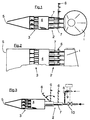
- FIG. 1 shows schematically in side view, partly in section, an embodiment of the headbox according to the invention. It can be seen a liquid supply device 1, which opens into a turbulence generator 2 consisting of several pipes 7. This is followed by an intermediate chamber 4, which downstream of another turbulence generator 3 follows.
- the stock suspension emerging from this second turbulence generator 3 during operation of the headbox is collected in a nozzle space and fed to an exit gap 5 from which it strikes, in the form of a wide nip, at least one paper machine wire.
- the intermediate chamber 4 may have a length which is 10 to 20 times greater than a step change of a turbulence generator designed as a stepped diffuser in order to achieve optimum mixing.
- FIG. 2 shows a device similar to that of FIG. 1, wherein the line 6 is the same in each case for all superimposed pipelines 7.
- the headbox shown in Figure 3 contains as the first turbulence generator 2 only a pipe 7, viewed in the vertical, which is also a stage diffuser. There are several points indicated where a line 6 may be present. In most cases, the non-dashed line, which opens into the first part of the turbulence generator, will be the most advantageous option. Both in this line 6 and in the supply line to the turbulence generator 2 each control valves are provided which can be controlled jointly via a control loop. As a further possibility to influence the flow in the turbulence generator 2 as desired, the change in the angle is indicated in Fig. 3, with which the line 6 opens into the turbulence generator 2. As a result, very specific impulses for better mixing can be generated. FIGS.
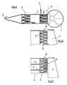
- the conduits 6 are spatially located in the region of the first turbulence generator 2 but open into the intermediate chamber 4.
- the turbulence generator 2 may also be formed by a block provided with flow channels 8 instead of by free-standing pipelines.
- the flow channels B expand gradually in the direction of flow, so they are designed as stepped diffusers.
- the intermediate chamber 4 is divided into sub-chambers by a number of walls 11 extending in the flow direction and perpendicular to the screen plane. In special cases, this can prevent unwanted cross-mixing in the intermediate chamber 4.
- the lines 6 open into the first part of the flow channels 8, which expand stepwise.
- FIG. 7 shows, albeit schematically, the technical structure of a turbulence generator 2 provided with step-diffuser-like flow channels 8.
- the lines 6 particularly simple, so with little construction effort is dargestelft: Within the Turbulenzerzeugerblokkes holes are introduced with a diameter transverse to the flow channels 8, that they cut the flow channels, whereby a connection between the flow channels and lines is made , Conveniently, two adjacent rows of superimposed flow channels are connected to the same supply line. This embodiment is shown in more detail in Fig.12.
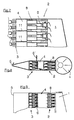
- the lines 6 may also lie within the second turbulence generator 3 and be connected to the intermediate chamber 4. In this way, a pulse is generated against the actual flow direction, which leads to a mixing of the supplied water with the suspension (FIGS. 8 and 9).
- FIG. 10 shows a somewhat simpler embodiment, in which two channels each lie one above the other in the turbulence generator 2 and the line 6 takes place only in one of the superimposed channels, in this case in the upper one.
- FIG. 11 shows the combination of supply of dilution water (arrow 12) in the turbulence generator 2 and withdrawal of suspension (arrow 13) in the turbulence generator 3.
- the invention can also be realized without difficulty in multi-layer drums, as FIG. 13 shows by way of example.
- the two-layer headbox shown there schematically has two independently loadable liquid feed devices 1, which downstream each two turbulence generators 2 and 3 connect, with each between an intermediate, chamber 4 and the last in the current direction turbulence generator 3, a nozzle chamber follows with a partition wall 14, at the end of the exit slit 5 is located.
Landscapes
- Paper (AREA)
Claims (15)
- Caisse de tête pour une machine à papier comprenant au moins un répartiteur d'écoulement transversal (1) auquel viennent se raccorder en aval au moins deux générateurs de turbulences à chaque fois formés par une pluralité d'éléments de génération de turbulence, une chambre intermédiaire (4) se trouvant entre deux générateurs de turbulences (2 et 3) successifs et le dernier générateur de turbulences dans le sens de l'écoulement étant suivi par une chambre de buse à l'extrémité de laquelle se trouve une fente de sortie (5) qui s'étend pour l'essentiel sur toute la largeur de la machine à papier et de laquelle peut sortir un jet de suspension lorsque la caisse de tête est en fonctionnement, caractérisée en ce que dans la zone à l'intérieur du générateur de turbulences (2) réalisé sous la forme d'un diffuseur à étages et qui se trouve devant la chambre intermédiaire (4) dans le sens de l'écoulement se trouvent des conduites (6) qui sont configurées et raccordées de telle sorte qu'un fluide peut être soit acheminé soit évacué à travers les conduites (6), ces conduites (6) étant reliées avec les conduites tubulaires (7) du générateur de turbulences (2) ou débouchant dans la chambre intermédiaire (4), et que la section transversale d'écoulement au niveau de l'entrée vers le générateur de turbulences (2) qui se trouve avant la chambre intermédiaire (4) peut être réglée et la quantité à travers les conduites (6) peut être ajustée par le biais d'une vanne de réglage (9) ou similaire de telle sorte que le réglage de la vanne (9) sur une conduite (6) donnée soit accordé sur le réglage d'une vanne (10) au niveau de l'entrée dans le générateur de turbulences qui se trouve devant la chambre intermédiaire (4).
- Caisse de tête pour une machine à papier comprenant au moins un répartiteur d'écoulement transversal (1) auquel viennent se raccorder en aval au moins deux générateurs de turbulences à chaque fois formés par une pluralité d'éléments de génération de turbulence, une chambre intermédiaire (4) se trouvant entre deux générateurs de turbulences (2 et 3) successifs et le dernier générateur de turbulences dans le sens de l'écoulement étant suivi par une chambre de buse à l'extrémité de laquelle se trouve une fente de sortie (5) qui s'étend pour l'essentiel sur toute la largeur de la machine à papier et de laquelle peut sortir un jet de suspension lorsque la caisse de tête est en fonctionnement, caractérisée en ce que dans la zone à l'intérieur du générateur de turbulences (3) réalisé sous la forme d'un diffuseur à étages et qui se trouve derrière la chambre intermédiaire (4) dans le sens de l'écoulement se trouvent des conduites (6') qui sont configurées et raccordées de telle sorte qu'un fluide peut être soit acheminé à travers celles-ci dans la chambre intermédiaire soit évacué à travers celles-ci hors de la chambre intermédiaire, le dispositif d'acheminement, dans le cas de l'acheminement du fluide, étant dirigé en sens inverse du sens de l'écoulement du jet de suspension en ce que le fluide est acheminé à la chambre intermédiaire (4) depuis son côté orienté vers le générateur de turbulences (3) afin de produire une impulsion contre le sens de l'écoulement proprement dit.
- Caisse de tête selon la revendication 1, caractérisée en ce que l'angle entre la conduite (6) et la conduite tubulaire (7) est réglable pendant le fonctionnement.
- Caisse de tête selon la revendication 1 ou 2, caractérisée en ce que le générateur de turbulences (2) qui se trouve devant la chambre intermédiaire (4) est réalisé sous la forme d'un sous-ensemble muni d'une pluralité de canaux d'écoulement (8), également appelés diffuseurs à étages, qui s'élargissent par palier.
- Caisse de tête selon la revendication 3 ou 4, caractérisée en ce que les conduites (6, 6') débouchent dans les canaux d'écoulement ou les conduites tubulaires.
- Caisse de tête selon la revendication 1 ou 4, caractérisée en ce que les conduites (6, 6') débouchent dans la chambre intermédiaire (4) depuis le côté orienté vers le générateur de turbulences (2) qui se trouve devant elle.
- Caisse de tête selon la revendication 4, caractérisée en ce que des canaux supplémentaires sont présents dans le sous-ensemble en plus des diffuseurs à étages pour le liquide acheminé ou évacué à travers les conduites (6, 6'), lesquels débouchent dans la chambre intermédiaire (4) depuis le côté orienté vers le générateur de turbulences (2) qui se trouve devant elle.
- Caisse de tête selon la revendication 1 ou 2, caractérisée en ce que les sections transversales d'écoulement au niveau de l'entrée vers le générateur de turbulences (2) qui se trouve devant la chambre intermédiaire (4) sont choisies de telle sorte qu'il se produit à cet endroit, lorsque la caisse de tête est en fonctionnement, une accélération à au moins le triple de la vitesse d'écoulement précédente.
- Caisse de tête selon la revendication 1, 2 ou 8, caractérisée en ce que la chute de pression au niveau du générateur de turbulences (2) qui se trouve devant la chambre intermédiaire (4) est égale à au moins 1,5 fois celle au niveau du générateur de turbulences (3) qui se trouve derrière la chambre intermédiaire (4).
- Caisse de tête selon la revendication 1 et 2, caractérisée en ce que les conduites (6) sont reliées avec une arrivée de liquide et les conduites (6') avec une évacuation de liquide.
- Caisse de tête selon la revendication 1, caractérisée en ce que les conduites (6) débouchent dans une première section du générateur de turbulences (2) qui se trouve devant la chambre intermédiaire (4).
- Caisse de tête selon la revendication 1, caractérisée en ce que la longueur de la chambre intermédiaire (4) dans le sens de l'écoulement est égale de 10 à 20 fois la cote du changement de palier entre l'avant-dernier élément et le dernier élément du générateur de turbulences (2) qui se trouve devant la chambre intermédiaire (4).
- Caisse de tête selon la revendication 1, caractérisée en ce que la chambre intermédiaire (4) est divisée en chambres partielles par des parois (11) qui s'étendent pour l'essentiel perpendiculairement au plan de la toile et dans le sens de l'écoulement.
- Caisse de tête selon la revendication 13, caractérisée en ce que les parois (11) présentent des portions de surface ouvertes de sorte qu'elles permettent un écoulement transversal limité dans la chambre intermédiaire (4).
- Caisse de tête selon l'une des revendications précédentes, caractérisée en ce qu'elle est réalisée sous la forme d'une caisse de tête multicouches comprenant deux dispositifs d'acheminement de liquide (1) ou plus auxquels se raccordent en aval à chaque fois au moins deux générateurs de turbulences par dispositif d'acheminement de liquide, une chambre intermédiaire (4) se trouvant à chaque fois entre deux générateurs de turbulences (2 et 3) successifs et le dernier générateur de turbulences dans le sens de l'écoulement étant suivi par une chambre de buse munie d'au moins une paroi de séparation (14) et à l'extrémité de laquelle se trouve la fente de sortie (5).
Applications Claiming Priority (2)
| Application Number | Priority Date | Filing Date | Title |
|---|---|---|---|
| DE4320243A DE4320243C2 (de) | 1993-06-18 | 1993-06-18 | Stoffauflauf für eine Papiermaschine |
| DE4320243 | 1993-06-18 |
Publications (3)
| Publication Number | Publication Date |
|---|---|
| EP0629739A1 EP0629739A1 (fr) | 1994-12-21 |
| EP0629739B1 EP0629739B1 (fr) | 1999-09-08 |
| EP0629739B2 true EP0629739B2 (fr) | 2006-04-19 |
Family
ID=6490642
Family Applications (1)
| Application Number | Title | Priority Date | Filing Date |
|---|---|---|---|
| EP94108842A Expired - Lifetime EP0629739B2 (fr) | 1993-06-18 | 1994-06-09 | Caisse de tête pour machine à papier |
Country Status (3)
| Country | Link |
|---|---|
| EP (1) | EP0629739B2 (fr) |
| AT (1) | ATE184336T1 (fr) |
| DE (2) | DE4320243C2 (fr) |
Families Citing this family (22)
| Publication number | Priority date | Publication date | Assignee | Title |
|---|---|---|---|---|
| US5560807A (en) * | 1995-03-29 | 1996-10-01 | Beloit Technologies, Inc. | Headbox additive injection system |
| US5626722A (en) * | 1995-06-01 | 1997-05-06 | Valmet Corporation | Headbox of a paper/board machine |
| US6210535B1 (en) | 1995-06-01 | 2001-04-03 | Valmet Corporation | Stock feed system for a multi-layer headbox and method in the operation of a multi-layer headbox |
| FI115646B (fi) * | 1996-11-26 | 2005-06-15 | Metso Paper Inc | Paperikoneen/kartonkikoneen monikerrosperälaatikko |
| DE19652442A1 (de) * | 1996-12-17 | 1998-06-18 | Voith Sulzer Papiermasch Gmbh | Verfahren und Vorrichtung zur Verteilung einer Faserstoffsuspension |
| DE19705591A1 (de) * | 1997-02-14 | 1998-08-20 | Voith Sulzer Papiermasch Gmbh | Vorrichtung und Verfahren zur Reinhaltung von Stauflächen |
| DE19705590A1 (de) * | 1997-02-14 | 1998-08-20 | Voith Sulzer Papiermasch Gmbh | Stoffauflauf einer Papiermaschine |
| DE19718034A1 (de) * | 1997-04-29 | 1998-11-05 | Voith Sulzer Papiermasch Gmbh | Stoffauflauf mit Dämpfungsverteiler |
| AU6695798A (en) * | 1997-04-29 | 1998-11-24 | Beloit Technologies, Inc. | High consistency stock profiling |
| US6117272A (en) * | 1998-09-03 | 2000-09-12 | Voith Sulzer Papiermaschinen | Device and process for metering auxiliary materials into the flow box of a paper machine |
| DE19926805A1 (de) * | 1999-06-12 | 2000-12-14 | Voith Sulzer Papiertech Patent | Stoffauflauf mit Fluidzudosierung |
| DE10208610B4 (de) * | 2002-02-27 | 2014-03-06 | Voith Patent Gmbh | Verfahren zum Verteilen einer Faserstoffsuspension im Stoffauflauf einer Papier- oder Kartonmaschine und Stoffauflauf |
| DE10233007B3 (de) * | 2002-07-20 | 2004-04-01 | Sächsisches Textilforschungsinstitut e.V. | Fahrzeugsitz, vorzugsweise Autokindersitz, mit wechselbarer Auflage |
| DE10331039A1 (de) * | 2003-07-09 | 2005-01-27 | Voith Paper Patent Gmbh | Stoffauflauf |
| EP1496150A1 (fr) * | 2003-07-09 | 2005-01-12 | Voith Paper Patent GmbH | Caisse de tête |
| DE102004055919A1 (de) * | 2004-11-19 | 2006-05-24 | Voith Paper Patent Gmbh | Stoffauflauf |
| DE102008054898A1 (de) | 2008-12-18 | 2010-06-24 | Voith Patent Gmbh | Stoffauflauf für eine Maschine zur Herstellung einer Faserstoffbahn |
| DE102008054896A1 (de) | 2008-12-18 | 2010-07-01 | Voith Patent Gmbh | Stoffauflauf für eine Maschine zur Herstellung einer Faserstoffbahn |
| DE102008054897A1 (de) | 2008-12-18 | 2010-07-01 | Voith Patent Gmbh | Stoffauflauf für eine Maschine zur Herstellung einer Faserstoffbahn |
| DE102009014268B3 (de) * | 2009-03-20 | 2010-04-08 | Andritz Küsters Gmbh | Anordnung an Papiermaschinen zur Einstellung eines Flächengewichts-Querprofils |
| CN103821023A (zh) * | 2014-03-03 | 2014-05-28 | 广东石油化工学院 | 一种互补式布浆器 |
| CN108166302A (zh) * | 2018-01-10 | 2018-06-15 | 浙江山鹰纸业有限公司 | 一种用于双网纸机的流浆箱 |
Citations (3)
| Publication number | Priority date | Publication date | Assignee | Title |
|---|---|---|---|---|
| US5030326A (en) † | 1988-05-13 | 1991-07-09 | S.E.M.T.I. Societe A Responsabilite Limitee | Paste-like mixture feed device |
| FI901593L (fi) † | 1990-03-30 | 1991-10-01 | Tampella Oy Ab | Foerfarande vid en pappers- eller kartongmaskin foer reglering av ur inloppslaodan loepande massa samt inloppslaoda foer en papperseller kartongmaskin. |
| EP0462472A1 (fr) † | 1990-06-20 | 1991-12-27 | J.M. Voith GmbH | Caisse de tête de machines à papier |
Family Cites Families (11)
| Publication number | Priority date | Publication date | Assignee | Title |
|---|---|---|---|---|
| US3573160A (en) * | 1969-01-29 | 1971-03-30 | Kasimir Lopas | Tapered manifold stock distribution system for a papermaking machine with movable wall therein |
| CH598407A5 (fr) * | 1975-09-30 | 1978-04-28 | Escher Wyss Gmbh | |
| FI66931C (fi) * | 1983-01-04 | 1984-12-10 | Tampella Oy Ab | Haolskiva foer en inloppslaoda foer en pappersmaskin |
| DE3514554C3 (de) * | 1984-09-19 | 1998-01-08 | Escher Wyss Gmbh | Stoffauflauf-Vorrichtung für eine Papiermaschine und Verfahren zu deren Betrieb |
| DE3741603A1 (de) * | 1987-12-09 | 1989-06-22 | Voith Gmbh J M | Stoffauflauf fuer eine papiermaschine od.dgl. |
| FI84920C (fi) * | 1988-05-27 | 1992-02-10 | Valmet Ahlstroem Inc | Hydraulisk inloppslaoda i pappers- eller kartongmaskin. |
| DE4005281C2 (de) * | 1990-02-20 | 1995-04-06 | Schultz Hans Joachim Dr Ing | Stoffauflauf mit Regelung des Flächengewicht-Querprofiles über die Verdünnung der Fasersuspension |
| US5196091A (en) * | 1991-10-29 | 1993-03-23 | Beloit Technologies, Inc. | Headbox apparatus with stock dilution conduits for basis weight control |
| DE9115296U1 (de) * | 1991-12-10 | 1992-03-19 | J.M. Voith Gmbh, 7920 Heidenheim | Stoffauflauf |
| DE4234940C2 (de) * | 1992-10-16 | 1994-04-07 | Voith Gmbh J M | Stoffauflauf mit Flächengewichts-Querprofilregelung durch lokale Konzentrationsänderung |
| DE4239845C2 (de) * | 1992-11-05 | 1998-12-03 | Voith Gmbh J M | Verfahren zur Messung der Auswirkung von Verstellungen am Stoffauflauf und zur Korrektur des Flächengewichts- und Faserorientierungs-Querprofils |
-
1993
- 1993-06-18 DE DE4320243A patent/DE4320243C2/de not_active Revoked
-
1994
- 1994-06-09 EP EP94108842A patent/EP0629739B2/fr not_active Expired - Lifetime
- 1994-06-09 DE DE59408713T patent/DE59408713D1/de not_active Expired - Fee Related
- 1994-06-09 AT AT94108842T patent/ATE184336T1/de not_active IP Right Cessation
Patent Citations (3)
| Publication number | Priority date | Publication date | Assignee | Title |
|---|---|---|---|---|
| US5030326A (en) † | 1988-05-13 | 1991-07-09 | S.E.M.T.I. Societe A Responsabilite Limitee | Paste-like mixture feed device |
| FI901593L (fi) † | 1990-03-30 | 1991-10-01 | Tampella Oy Ab | Foerfarande vid en pappers- eller kartongmaskin foer reglering av ur inloppslaodan loepande massa samt inloppslaoda foer en papperseller kartongmaskin. |
| EP0462472A1 (fr) † | 1990-06-20 | 1991-12-27 | J.M. Voith GmbH | Caisse de tête de machines à papier |
Non-Patent Citations (3)
| Title |
|---|
| B. Wahlstrom et al.: "Headbox design development, high speed and slow speed" TAPPI Seminar Notes/1982 Wet End Operations, Seiten 29 bis 280 † |
| J. Hämäläinen: "Mathematical modelling and simulation of fluid flows in the headbox of paper machines", Bericht 57, Universität Jyväskylä, Mathematisches Institut, 1993 † |
| T.E. Faulkner: "The Step Diffusor Headbox", TAPPI Seminar Notes/1982 Wet End Operations, Seiten 277 bis 280 † |
Also Published As
| Publication number | Publication date |
|---|---|
| EP0629739A1 (fr) | 1994-12-21 |
| DE4320243C2 (de) | 1996-02-22 |
| DE59408713D1 (de) | 1999-10-14 |
| EP0629739B1 (fr) | 1999-09-08 |
| ATE184336T1 (de) | 1999-09-15 |
| DE4320243A1 (de) | 1994-12-22 |
Similar Documents
| Publication | Publication Date | Title |
|---|---|---|
| EP0629739B2 (fr) | Caisse de tête pour machine à papier | |
| DE3741603C2 (fr) | ||
| DE4323263C2 (de) | Verfahren zur sektionalen Beeinflussung der Stoffdichte und der Faserorientierung in einem Stoffauflauf einer Papiermaschine und Stoffauflauf zur Durchführung des Verfahrens | |
| DE69913450T2 (de) | Stoffauflauf zur Verteilung von Faserstoffsuspension und Zusatzstoffe | |
| DE4416909C2 (de) | Stoffauflauf für eine Papiermaschine | |
| EP2379800A1 (fr) | Caisse de tête pour machine de fabrication d'une bande de matière fibreuse | |
| DE4416898C2 (de) | Stoffauflauf für eine Papiermaschine mit lokaler Zumischung von Fluid | |
| EP2464782A2 (fr) | Caisse de tête pour une machine servant à fabriquer une bande de matière fibreuse et machine | |
| WO2010069651A1 (fr) | Caisson de tête pour machine de fabrication d'une bande de matière fibreuse | |
| EP2454411A1 (fr) | Caisse de tête pour une machine de fabrication d une bande de matière fibreuse | |
| WO2010069652A1 (fr) | Caisson de tête pour machine de fabrication d'une bande de matière fibreuse | |
| WO1993022495A1 (fr) | Agencement de caisse de tete pour machines a papier | |
| DE1511218C3 (de) | Papierbrei-Aufgabevorrichtung für Papiermaschinen | |
| DE4409415C5 (de) | Dosiervorrichtung für einen Stoffauflauf einer Papiermaschine | |
| EP1033436B1 (fr) | Procédé et dispositif pour le dosage d'un milieu fluide dans l'écoulement d'une suspension dans une caisse de tête | |
| DE4435860C2 (de) | Stoffauflauf zur Erzeugung einer mehrschichtigen Papierbahn | |
| DE102011003849A1 (de) | Stoffauflauf für eine Maschine zur Herstellung einer Faserstoffbahn | |
| DE602004006888T2 (de) | Stoffauflaufkasten einer papiermaschine | |
| EP0683266A1 (fr) | Caisse de tête pour une machine à papier avec addition locale de fluide | |
| EP2585633B1 (fr) | Caisse de tête pour une machine de production d'une bande de matière fibreuse | |
| EP1676950B1 (fr) | Caisse de tête pour machine de fabrication d'une bande fibreuse, une bande de papier ou de carton | |
| DE102018120162A1 (de) | Stoffauflauf | |
| DE4140657A1 (de) | Stoffauflauf | |
| EP0708201A1 (fr) | Caisse de tête d'une machine à papier | |
| DE9320495U1 (de) | Stoffauflaufeinrichtung für eine Papiermaschine |
Legal Events
| Date | Code | Title | Description |
|---|---|---|---|
| PUAI | Public reference made under article 153(3) epc to a published international application that has entered the european phase |
Free format text: ORIGINAL CODE: 0009012 |
|
| 17P | Request for examination filed |
Effective date: 19940609 |
|
| AK | Designated contracting states |
Kind code of ref document: A1 Designated state(s): AT DE FR GB SE |
|
| RAP1 | Party data changed (applicant data changed or rights of an application transferred) |
Owner name: VOITH SULZER PAPIERMASCHINEN GMBH |
|
| 17Q | First examination report despatched |
Effective date: 19970311 |
|
| RAP1 | Party data changed (applicant data changed or rights of an application transferred) |
Owner name: VOITH SULZER PAPIERTECHNIK PATENT GMBH |
|
| GRAG | Despatch of communication of intention to grant |
Free format text: ORIGINAL CODE: EPIDOS AGRA |
|
| GRAG | Despatch of communication of intention to grant |
Free format text: ORIGINAL CODE: EPIDOS AGRA |
|
| GRAH | Despatch of communication of intention to grant a patent |
Free format text: ORIGINAL CODE: EPIDOS IGRA |
|
| GRAH | Despatch of communication of intention to grant a patent |
Free format text: ORIGINAL CODE: EPIDOS IGRA |
|
| GRAA | (expected) grant |
Free format text: ORIGINAL CODE: 0009210 |
|
| AK | Designated contracting states |
Kind code of ref document: B1 Designated state(s): AT DE FR GB SE |
|
| PG25 | Lapsed in a contracting state [announced via postgrant information from national office to epo] |
Ref country code: GB Free format text: LAPSE BECAUSE OF FAILURE TO SUBMIT A TRANSLATION OF THE DESCRIPTION OR TO PAY THE FEE WITHIN THE PRESCRIBED TIME-LIMIT Effective date: 19990908 Ref country code: FR Free format text: LAPSE BECAUSE OF FAILURE TO SUBMIT A TRANSLATION OF THE DESCRIPTION OR TO PAY THE FEE WITHIN THE PRESCRIBED TIME-LIMIT Effective date: 19990908 |
|
| REF | Corresponds to: |
Ref document number: 184336 Country of ref document: AT Date of ref document: 19990915 Kind code of ref document: T |
|
| REF | Corresponds to: |
Ref document number: 59408713 Country of ref document: DE Date of ref document: 19991014 |
|
| EN | Fr: translation not filed | ||
| GBV | Gb: ep patent (uk) treated as always having been void in accordance with gb section 77(7)/1977 [no translation filed] |
Effective date: 19990908 |
|
| EUG | Se: european patent has lapsed | ||
| PLBQ | Unpublished change to opponent data |
Free format text: ORIGINAL CODE: EPIDOS OPPO |
|
| PLBI | Opposition filed |
Free format text: ORIGINAL CODE: 0009260 |
|
| PLBF | Reply of patent proprietor to notice(s) of opposition |
Free format text: ORIGINAL CODE: EPIDOS OBSO |
|
| 26 | Opposition filed |
Opponent name: VALMET CORPORATION Effective date: 20000607 |
|
| PLBF | Reply of patent proprietor to notice(s) of opposition |
Free format text: ORIGINAL CODE: EPIDOS OBSO |
|
| PLAW | Interlocutory decision in opposition |
Free format text: ORIGINAL CODE: EPIDOS IDOP |
|
| APAC | Appeal dossier modified |
Free format text: ORIGINAL CODE: EPIDOS NOAPO |
|
| APBQ | Date of receipt of statement of grounds of appeal recorded |
Free format text: ORIGINAL CODE: EPIDOSNNOA3O |
|
| APBA | Date of receipt of statement of grounds of appeal deleted |
Free format text: ORIGINAL CODE: EPIDOSDNOA3O |
|
| APBQ | Date of receipt of statement of grounds of appeal recorded |
Free format text: ORIGINAL CODE: EPIDOSNNOA3O |
|
| APAA | Appeal reference recorded |
Free format text: ORIGINAL CODE: EPIDOS REFN |
|
| APBU | Appeal procedure closed |
Free format text: ORIGINAL CODE: EPIDOSNNOA9O |
|
| PLAB | Opposition data, opponent's data or that of the opponent's representative modified |
Free format text: ORIGINAL CODE: 0009299OPPO |
|
| APAH | Appeal reference modified |
Free format text: ORIGINAL CODE: EPIDOSCREFNO |
|
| PUAH | Patent maintained in amended form |
Free format text: ORIGINAL CODE: 0009272 |
|
| STAA | Information on the status of an ep patent application or granted ep patent |
Free format text: STATUS: PATENT MAINTAINED AS AMENDED |
|
| 27A | Patent maintained in amended form |
Effective date: 20060419 |
|
| AK | Designated contracting states |
Kind code of ref document: B2 Designated state(s): AT DE FR GB SE |
|
| PGFP | Annual fee paid to national office [announced via postgrant information from national office to epo] |
Ref country code: SE Payment date: 20060614 Year of fee payment: 13 |
|
| PGFP | Annual fee paid to national office [announced via postgrant information from national office to epo] |
Ref country code: DE Payment date: 20060616 Year of fee payment: 13 Ref country code: AT Payment date: 20060616 Year of fee payment: 13 |
|
| REG | Reference to a national code |
Ref country code: SE Ref legal event code: RPEO |
|
| EN | Fr: translation not filed | ||
| EUG | Se: european patent has lapsed | ||
| PG25 | Lapsed in a contracting state [announced via postgrant information from national office to epo] |
Ref country code: AT Free format text: LAPSE BECAUSE OF NON-PAYMENT OF DUE FEES Effective date: 20070609 |
|
| PG25 | Lapsed in a contracting state [announced via postgrant information from national office to epo] |
Ref country code: DE Free format text: LAPSE BECAUSE OF NON-PAYMENT OF DUE FEES Effective date: 20080101 |
|
| PG25 | Lapsed in a contracting state [announced via postgrant information from national office to epo] |
Ref country code: SE Free format text: LAPSE BECAUSE OF NON-PAYMENT OF DUE FEES Effective date: 20070610 |