EP0629809A1 - Lagerbehälter für Kohlenwasserstoffe unter Druck - Google Patents
Lagerbehälter für Kohlenwasserstoffe unter Druck Download PDFInfo
- Publication number
- EP0629809A1 EP0629809A1 EP94401200A EP94401200A EP0629809A1 EP 0629809 A1 EP0629809 A1 EP 0629809A1 EP 94401200 A EP94401200 A EP 94401200A EP 94401200 A EP94401200 A EP 94401200A EP 0629809 A1 EP0629809 A1 EP 0629809A1
- Authority
- EP
- European Patent Office
- Prior art keywords
- containers
- container
- sheath
- fluid
- control means
- Prior art date
- Legal status (The legal status is an assumption and is not a legal conclusion. Google has not performed a legal analysis and makes no representation as to the accuracy of the status listed.)
- Granted
Links
- 229930195733 hydrocarbon Natural products 0.000 title claims abstract description 39
- 150000002430 hydrocarbons Chemical class 0.000 title claims abstract description 39
- 238000003860 storage Methods 0.000 title claims description 22
- 239000012530 fluid Substances 0.000 claims abstract description 25
- VNWKTOKETHGBQD-UHFFFAOYSA-N methane Chemical compound C VNWKTOKETHGBQD-UHFFFAOYSA-N 0.000 claims description 28
- 239000003345 natural gas Substances 0.000 claims description 11
- 239000000463 material Substances 0.000 claims description 8
- 230000003014 reinforcing effect Effects 0.000 claims description 8
- 239000000835 fiber Substances 0.000 claims description 6
- 229920005989 resin Polymers 0.000 claims description 6
- 239000011347 resin Substances 0.000 claims description 6
- 229910052751 metal Inorganic materials 0.000 claims description 5
- 239000002184 metal Substances 0.000 claims description 5
- 230000002787 reinforcement Effects 0.000 claims description 5
- 238000012546 transfer Methods 0.000 claims description 4
- 239000002033 PVDF binder Substances 0.000 claims description 3
- 239000004952 Polyamide Substances 0.000 claims description 3
- 239000004917 carbon fiber Substances 0.000 claims description 3
- 230000001413 cellular effect Effects 0.000 claims description 3
- 239000003365 glass fiber Substances 0.000 claims description 3
- 229920001903 high density polyethylene Polymers 0.000 claims description 3
- 239000004700 high-density polyethylene Substances 0.000 claims description 3
- 229920002647 polyamide Polymers 0.000 claims description 3
- 229920002981 polyvinylidene fluoride Polymers 0.000 claims description 3
- 229920000049 Carbon (fiber) Polymers 0.000 claims description 2
- 229920002635 polyurethane Polymers 0.000 claims description 2
- 239000004814 polyurethane Substances 0.000 claims description 2
- 239000012815 thermoplastic material Substances 0.000 claims description 2
- 238000012544 monitoring process Methods 0.000 claims 1
- 239000004215 Carbon black (E152) Substances 0.000 abstract description 21
- 238000005429 filling process Methods 0.000 abstract 1
- 239000007789 gas Substances 0.000 description 17
- 238000009826 distribution Methods 0.000 description 10
- 239000000446 fuel Substances 0.000 description 9
- ATUOYWHBWRKTHZ-UHFFFAOYSA-N Propane Chemical compound CCC ATUOYWHBWRKTHZ-UHFFFAOYSA-N 0.000 description 6
- 238000010438 heat treatment Methods 0.000 description 6
- 239000010410 layer Substances 0.000 description 5
- -1 for example Substances 0.000 description 4
- 239000003915 liquefied petroleum gas Substances 0.000 description 4
- 239000012783 reinforcing fiber Substances 0.000 description 4
- OTMSDBZUPAUEDD-UHFFFAOYSA-N Ethane Chemical compound CC OTMSDBZUPAUEDD-UHFFFAOYSA-N 0.000 description 3
- 229910052782 aluminium Inorganic materials 0.000 description 3
- XAGFODPZIPBFFR-UHFFFAOYSA-N aluminium Chemical compound [Al] XAGFODPZIPBFFR-UHFFFAOYSA-N 0.000 description 3
- 239000001273 butane Substances 0.000 description 3
- IJDNQMDRQITEOD-UHFFFAOYSA-N n-butane Chemical compound CCCC IJDNQMDRQITEOD-UHFFFAOYSA-N 0.000 description 3
- OFBQJSOFQDEBGM-UHFFFAOYSA-N n-pentane Natural products CCCCC OFBQJSOFQDEBGM-UHFFFAOYSA-N 0.000 description 3
- 239000004033 plastic Substances 0.000 description 3
- 229920003023 plastic Polymers 0.000 description 3
- 239000001294 propane Substances 0.000 description 3
- 229920001169 thermoplastic Polymers 0.000 description 3
- 229920005992 thermoplastic resin Polymers 0.000 description 3
- 238000004804 winding Methods 0.000 description 3
- OKTJSMMVPCPJKN-UHFFFAOYSA-N Carbon Chemical compound [C] OKTJSMMVPCPJKN-UHFFFAOYSA-N 0.000 description 2
- 229910000831 Steel Inorganic materials 0.000 description 2
- 230000002159 abnormal effect Effects 0.000 description 2
- 229910052799 carbon Inorganic materials 0.000 description 2
- 239000003638 chemical reducing agent Substances 0.000 description 2
- 238000004891 communication Methods 0.000 description 2
- 239000002131 composite material Substances 0.000 description 2
- 230000006866 deterioration Effects 0.000 description 2
- 230000000694 effects Effects 0.000 description 2
- 235000021183 entrée Nutrition 0.000 description 2
- 230000001681 protective effect Effects 0.000 description 2
- 239000011241 protective layer Substances 0.000 description 2
- 229910001220 stainless steel Inorganic materials 0.000 description 2
- 239000010935 stainless steel Substances 0.000 description 2
- 239000010959 steel Substances 0.000 description 2
- 229920001187 thermosetting polymer Polymers 0.000 description 2
- 239000004416 thermosoftening plastic Substances 0.000 description 2
- KXGFMDJXCMQABM-UHFFFAOYSA-N 2-methoxy-6-methylphenol Chemical compound [CH]OC1=CC=CC([CH])=C1O KXGFMDJXCMQABM-UHFFFAOYSA-N 0.000 description 1
- 239000004593 Epoxy Substances 0.000 description 1
- 239000004698 Polyethylene Substances 0.000 description 1
- 239000004743 Polypropylene Substances 0.000 description 1
- 229920005830 Polyurethane Foam Polymers 0.000 description 1
- 230000006978 adaptation Effects 0.000 description 1
- 230000032683 aging Effects 0.000 description 1
- 239000004760 aramid Substances 0.000 description 1
- 229920003235 aromatic polyamide Polymers 0.000 description 1
- 230000015556 catabolic process Effects 0.000 description 1
- 238000002485 combustion reaction Methods 0.000 description 1
- 230000006837 decompression Effects 0.000 description 1
- 238000006731 degradation reaction Methods 0.000 description 1
- 238000011161 development Methods 0.000 description 1
- 230000018109 developmental process Effects 0.000 description 1
- 238000010586 diagram Methods 0.000 description 1
- 238000007599 discharging Methods 0.000 description 1
- 229920001971 elastomer Polymers 0.000 description 1
- 239000000806 elastomer Substances 0.000 description 1
- 239000013536 elastomeric material Substances 0.000 description 1
- 230000007613 environmental effect Effects 0.000 description 1
- 230000001747 exhibiting effect Effects 0.000 description 1
- 238000004880 explosion Methods 0.000 description 1
- 230000006355 external stress Effects 0.000 description 1
- 238000001125 extrusion Methods 0.000 description 1
- 239000011521 glass Substances 0.000 description 1
- 239000007788 liquid Substances 0.000 description 1
- 238000004519 manufacturing process Methods 0.000 description 1
- 239000011159 matrix material Substances 0.000 description 1
- 238000000034 method Methods 0.000 description 1
- 238000002156 mixing Methods 0.000 description 1
- 239000000203 mixture Substances 0.000 description 1
- 238000012986 modification Methods 0.000 description 1
- 230000004048 modification Effects 0.000 description 1
- 238000013021 overheating Methods 0.000 description 1
- 230000035699 permeability Effects 0.000 description 1
- 239000003208 petroleum Substances 0.000 description 1
- 229920001568 phenolic resin Polymers 0.000 description 1
- 239000005011 phenolic resin Substances 0.000 description 1
- 229920000728 polyester Polymers 0.000 description 1
- 229920000573 polyethylene Polymers 0.000 description 1
- 229920001155 polypropylene Polymers 0.000 description 1
- 239000011496 polyurethane foam Substances 0.000 description 1
- 239000005060 rubber Substances 0.000 description 1
- 238000007789 sealing Methods 0.000 description 1
- 230000035939 shock Effects 0.000 description 1
- 239000000126 substance Substances 0.000 description 1
- 238000006467 substitution reaction Methods 0.000 description 1
- 239000012209 synthetic fiber Substances 0.000 description 1
- 229920002994 synthetic fiber Polymers 0.000 description 1
- 238000012360 testing method Methods 0.000 description 1
- 229920002725 thermoplastic elastomer Polymers 0.000 description 1
- 238000009827 uniform distribution Methods 0.000 description 1
- 229920001567 vinyl ester resin Polymers 0.000 description 1
Images

Classifications
-
- F—MECHANICAL ENGINEERING; LIGHTING; HEATING; WEAPONS; BLASTING
- F17—STORING OR DISTRIBUTING GASES OR LIQUIDS
- F17C—VESSELS FOR CONTAINING OR STORING COMPRESSED, LIQUEFIED OR SOLIDIFIED GASES; FIXED-CAPACITY GAS-HOLDERS; FILLING VESSELS WITH, OR DISCHARGING FROM VESSELS, COMPRESSED, LIQUEFIED, OR SOLIDIFIED GASES
- F17C5/00—Methods or apparatus for filling containers with liquefied, solidified, or compressed gases under pressures
- F17C5/06—Methods or apparatus for filling containers with liquefied, solidified, or compressed gases under pressures for filling with compressed gases
-
- B—PERFORMING OPERATIONS; TRANSPORTING
- B60—VEHICLES IN GENERAL
- B60K—ARRANGEMENT OR MOUNTING OF PROPULSION UNITS OR OF TRANSMISSIONS IN VEHICLES; ARRANGEMENT OR MOUNTING OF PLURAL DIVERSE PRIME-MOVERS IN VEHICLES; AUXILIARY DRIVES FOR VEHICLES; INSTRUMENTATION OR DASHBOARDS FOR VEHICLES; ARRANGEMENTS IN CONNECTION WITH COOLING, AIR INTAKE, GAS EXHAUST OR FUEL SUPPLY OF PROPULSION UNITS IN VEHICLES
- B60K15/00—Arrangement in connection with fuel supply of combustion engines or other fuel consuming energy converters, e.g. fuel cells; Mounting or construction of fuel tanks
- B60K15/03—Fuel tanks
- B60K15/063—Arrangement of tanks
- B60K15/067—Mounting of tanks
- B60K15/07—Mounting of tanks of gas tanks
-
- F—MECHANICAL ENGINEERING; LIGHTING; HEATING; WEAPONS; BLASTING
- F17—STORING OR DISTRIBUTING GASES OR LIQUIDS
- F17C—VESSELS FOR CONTAINING OR STORING COMPRESSED, LIQUEFIED OR SOLIDIFIED GASES; FIXED-CAPACITY GAS-HOLDERS; FILLING VESSELS WITH, OR DISCHARGING FROM VESSELS, COMPRESSED, LIQUEFIED, OR SOLIDIFIED GASES
- F17C1/00—Pressure vessels, e.g. gas cylinder, gas tank, replaceable cartridge
- F17C1/02—Pressure vessels, e.g. gas cylinder, gas tank, replaceable cartridge involving reinforcing arrangements
- F17C1/04—Protecting sheathings
- F17C1/06—Protecting sheathings built-up from wound-on bands or filamentary material, e.g. wires
-
- F—MECHANICAL ENGINEERING; LIGHTING; HEATING; WEAPONS; BLASTING
- F17—STORING OR DISTRIBUTING GASES OR LIQUIDS
- F17C—VESSELS FOR CONTAINING OR STORING COMPRESSED, LIQUEFIED OR SOLIDIFIED GASES; FIXED-CAPACITY GAS-HOLDERS; FILLING VESSELS WITH, OR DISCHARGING FROM VESSELS, COMPRESSED, LIQUEFIED, OR SOLIDIFIED GASES
- F17C2201/00—Vessel construction, in particular geometry, arrangement or size
- F17C2201/01—Shape
- F17C2201/0104—Shape cylindrical
- F17C2201/0119—Shape cylindrical with flat end-piece
-
- F—MECHANICAL ENGINEERING; LIGHTING; HEATING; WEAPONS; BLASTING
- F17—STORING OR DISTRIBUTING GASES OR LIQUIDS
- F17C—VESSELS FOR CONTAINING OR STORING COMPRESSED, LIQUEFIED OR SOLIDIFIED GASES; FIXED-CAPACITY GAS-HOLDERS; FILLING VESSELS WITH, OR DISCHARGING FROM VESSELS, COMPRESSED, LIQUEFIED, OR SOLIDIFIED GASES
- F17C2201/00—Vessel construction, in particular geometry, arrangement or size
- F17C2201/01—Shape
- F17C2201/0104—Shape cylindrical
- F17C2201/0123—Shape cylindrical with variable thickness or diameter
-
- F—MECHANICAL ENGINEERING; LIGHTING; HEATING; WEAPONS; BLASTING
- F17—STORING OR DISTRIBUTING GASES OR LIQUIDS
- F17C—VESSELS FOR CONTAINING OR STORING COMPRESSED, LIQUEFIED OR SOLIDIFIED GASES; FIXED-CAPACITY GAS-HOLDERS; FILLING VESSELS WITH, OR DISCHARGING FROM VESSELS, COMPRESSED, LIQUEFIED, OR SOLIDIFIED GASES
- F17C2201/00—Vessel construction, in particular geometry, arrangement or size
- F17C2201/05—Size
- F17C2201/054—Size medium (>1 m3)
-
- F—MECHANICAL ENGINEERING; LIGHTING; HEATING; WEAPONS; BLASTING
- F17—STORING OR DISTRIBUTING GASES OR LIQUIDS
- F17C—VESSELS FOR CONTAINING OR STORING COMPRESSED, LIQUEFIED OR SOLIDIFIED GASES; FIXED-CAPACITY GAS-HOLDERS; FILLING VESSELS WITH, OR DISCHARGING FROM VESSELS, COMPRESSED, LIQUEFIED, OR SOLIDIFIED GASES
- F17C2201/00—Vessel construction, in particular geometry, arrangement or size
- F17C2201/05—Size
- F17C2201/056—Small (<1 m3)
-
- F—MECHANICAL ENGINEERING; LIGHTING; HEATING; WEAPONS; BLASTING
- F17—STORING OR DISTRIBUTING GASES OR LIQUIDS
- F17C—VESSELS FOR CONTAINING OR STORING COMPRESSED, LIQUEFIED OR SOLIDIFIED GASES; FIXED-CAPACITY GAS-HOLDERS; FILLING VESSELS WITH, OR DISCHARGING FROM VESSELS, COMPRESSED, LIQUEFIED, OR SOLIDIFIED GASES
- F17C2201/00—Vessel construction, in particular geometry, arrangement or size
- F17C2201/05—Size
- F17C2201/058—Size portable (<30 l)
-
- F—MECHANICAL ENGINEERING; LIGHTING; HEATING; WEAPONS; BLASTING
- F17—STORING OR DISTRIBUTING GASES OR LIQUIDS
- F17C—VESSELS FOR CONTAINING OR STORING COMPRESSED, LIQUEFIED OR SOLIDIFIED GASES; FIXED-CAPACITY GAS-HOLDERS; FILLING VESSELS WITH, OR DISCHARGING FROM VESSELS, COMPRESSED, LIQUEFIED, OR SOLIDIFIED GASES
- F17C2203/00—Vessel construction, in particular walls or details thereof
- F17C2203/01—Reinforcing or suspension means
- F17C2203/011—Reinforcing means
- F17C2203/012—Reinforcing means on or in the wall, e.g. ribs
-
- F—MECHANICAL ENGINEERING; LIGHTING; HEATING; WEAPONS; BLASTING
- F17—STORING OR DISTRIBUTING GASES OR LIQUIDS
- F17C—VESSELS FOR CONTAINING OR STORING COMPRESSED, LIQUEFIED OR SOLIDIFIED GASES; FIXED-CAPACITY GAS-HOLDERS; FILLING VESSELS WITH, OR DISCHARGING FROM VESSELS, COMPRESSED, LIQUEFIED, OR SOLIDIFIED GASES
- F17C2203/00—Vessel construction, in particular walls or details thereof
- F17C2203/06—Materials for walls or layers thereof; Properties or structures of walls or their materials
- F17C2203/0602—Wall structures; Special features thereof
- F17C2203/0607—Coatings
-
- F—MECHANICAL ENGINEERING; LIGHTING; HEATING; WEAPONS; BLASTING
- F17—STORING OR DISTRIBUTING GASES OR LIQUIDS
- F17C—VESSELS FOR CONTAINING OR STORING COMPRESSED, LIQUEFIED OR SOLIDIFIED GASES; FIXED-CAPACITY GAS-HOLDERS; FILLING VESSELS WITH, OR DISCHARGING FROM VESSELS, COMPRESSED, LIQUEFIED, OR SOLIDIFIED GASES
- F17C2203/00—Vessel construction, in particular walls or details thereof
- F17C2203/06—Materials for walls or layers thereof; Properties or structures of walls or their materials
- F17C2203/0602—Wall structures; Special features thereof
- F17C2203/0612—Wall structures
- F17C2203/0614—Single wall
- F17C2203/0621—Single wall with three layers
-
- F—MECHANICAL ENGINEERING; LIGHTING; HEATING; WEAPONS; BLASTING
- F17—STORING OR DISTRIBUTING GASES OR LIQUIDS
- F17C—VESSELS FOR CONTAINING OR STORING COMPRESSED, LIQUEFIED OR SOLIDIFIED GASES; FIXED-CAPACITY GAS-HOLDERS; FILLING VESSELS WITH, OR DISCHARGING FROM VESSELS, COMPRESSED, LIQUEFIED, OR SOLIDIFIED GASES
- F17C2203/00—Vessel construction, in particular walls or details thereof
- F17C2203/06—Materials for walls or layers thereof; Properties or structures of walls or their materials
- F17C2203/0634—Materials for walls or layers thereof
- F17C2203/0636—Metals
-
- F—MECHANICAL ENGINEERING; LIGHTING; HEATING; WEAPONS; BLASTING
- F17—STORING OR DISTRIBUTING GASES OR LIQUIDS
- F17C—VESSELS FOR CONTAINING OR STORING COMPRESSED, LIQUEFIED OR SOLIDIFIED GASES; FIXED-CAPACITY GAS-HOLDERS; FILLING VESSELS WITH, OR DISCHARGING FROM VESSELS, COMPRESSED, LIQUEFIED, OR SOLIDIFIED GASES
- F17C2203/00—Vessel construction, in particular walls or details thereof
- F17C2203/06—Materials for walls or layers thereof; Properties or structures of walls or their materials
- F17C2203/0634—Materials for walls or layers thereof
- F17C2203/0636—Metals
- F17C2203/0639—Steels
-
- F—MECHANICAL ENGINEERING; LIGHTING; HEATING; WEAPONS; BLASTING
- F17—STORING OR DISTRIBUTING GASES OR LIQUIDS
- F17C—VESSELS FOR CONTAINING OR STORING COMPRESSED, LIQUEFIED OR SOLIDIFIED GASES; FIXED-CAPACITY GAS-HOLDERS; FILLING VESSELS WITH, OR DISCHARGING FROM VESSELS, COMPRESSED, LIQUEFIED, OR SOLIDIFIED GASES
- F17C2203/00—Vessel construction, in particular walls or details thereof
- F17C2203/06—Materials for walls or layers thereof; Properties or structures of walls or their materials
- F17C2203/0634—Materials for walls or layers thereof
- F17C2203/0636—Metals
- F17C2203/0639—Steels
- F17C2203/0643—Stainless steels
-
- F—MECHANICAL ENGINEERING; LIGHTING; HEATING; WEAPONS; BLASTING
- F17—STORING OR DISTRIBUTING GASES OR LIQUIDS
- F17C—VESSELS FOR CONTAINING OR STORING COMPRESSED, LIQUEFIED OR SOLIDIFIED GASES; FIXED-CAPACITY GAS-HOLDERS; FILLING VESSELS WITH, OR DISCHARGING FROM VESSELS, COMPRESSED, LIQUEFIED, OR SOLIDIFIED GASES
- F17C2203/00—Vessel construction, in particular walls or details thereof
- F17C2203/06—Materials for walls or layers thereof; Properties or structures of walls or their materials
- F17C2203/0634—Materials for walls or layers thereof
- F17C2203/0636—Metals
- F17C2203/0646—Aluminium
-
- F—MECHANICAL ENGINEERING; LIGHTING; HEATING; WEAPONS; BLASTING
- F17—STORING OR DISTRIBUTING GASES OR LIQUIDS
- F17C—VESSELS FOR CONTAINING OR STORING COMPRESSED, LIQUEFIED OR SOLIDIFIED GASES; FIXED-CAPACITY GAS-HOLDERS; FILLING VESSELS WITH, OR DISCHARGING FROM VESSELS, COMPRESSED, LIQUEFIED, OR SOLIDIFIED GASES
- F17C2203/00—Vessel construction, in particular walls or details thereof
- F17C2203/06—Materials for walls or layers thereof; Properties or structures of walls or their materials
- F17C2203/0634—Materials for walls or layers thereof
- F17C2203/0658—Synthetics
-
- F—MECHANICAL ENGINEERING; LIGHTING; HEATING; WEAPONS; BLASTING
- F17—STORING OR DISTRIBUTING GASES OR LIQUIDS
- F17C—VESSELS FOR CONTAINING OR STORING COMPRESSED, LIQUEFIED OR SOLIDIFIED GASES; FIXED-CAPACITY GAS-HOLDERS; FILLING VESSELS WITH, OR DISCHARGING FROM VESSELS, COMPRESSED, LIQUEFIED, OR SOLIDIFIED GASES
- F17C2203/00—Vessel construction, in particular walls or details thereof
- F17C2203/06—Materials for walls or layers thereof; Properties or structures of walls or their materials
- F17C2203/0634—Materials for walls or layers thereof
- F17C2203/0658—Synthetics
- F17C2203/066—Plastics
-
- F—MECHANICAL ENGINEERING; LIGHTING; HEATING; WEAPONS; BLASTING
- F17—STORING OR DISTRIBUTING GASES OR LIQUIDS
- F17C—VESSELS FOR CONTAINING OR STORING COMPRESSED, LIQUEFIED OR SOLIDIFIED GASES; FIXED-CAPACITY GAS-HOLDERS; FILLING VESSELS WITH, OR DISCHARGING FROM VESSELS, COMPRESSED, LIQUEFIED, OR SOLIDIFIED GASES
- F17C2203/00—Vessel construction, in particular walls or details thereof
- F17C2203/06—Materials for walls or layers thereof; Properties or structures of walls or their materials
- F17C2203/0634—Materials for walls or layers thereof
- F17C2203/0658—Synthetics
- F17C2203/0663—Synthetics in form of fibers or filaments
-
- F—MECHANICAL ENGINEERING; LIGHTING; HEATING; WEAPONS; BLASTING
- F17—STORING OR DISTRIBUTING GASES OR LIQUIDS
- F17C—VESSELS FOR CONTAINING OR STORING COMPRESSED, LIQUEFIED OR SOLIDIFIED GASES; FIXED-CAPACITY GAS-HOLDERS; FILLING VESSELS WITH, OR DISCHARGING FROM VESSELS, COMPRESSED, LIQUEFIED, OR SOLIDIFIED GASES
- F17C2203/00—Vessel construction, in particular walls or details thereof
- F17C2203/06—Materials for walls or layers thereof; Properties or structures of walls or their materials
- F17C2203/0634—Materials for walls or layers thereof
- F17C2203/0658—Synthetics
- F17C2203/0663—Synthetics in form of fibers or filaments
- F17C2203/0668—Synthetics in form of fibers or filaments axially wound
-
- F—MECHANICAL ENGINEERING; LIGHTING; HEATING; WEAPONS; BLASTING
- F17—STORING OR DISTRIBUTING GASES OR LIQUIDS
- F17C—VESSELS FOR CONTAINING OR STORING COMPRESSED, LIQUEFIED OR SOLIDIFIED GASES; FIXED-CAPACITY GAS-HOLDERS; FILLING VESSELS WITH, OR DISCHARGING FROM VESSELS, COMPRESSED, LIQUEFIED, OR SOLIDIFIED GASES
- F17C2203/00—Vessel construction, in particular walls or details thereof
- F17C2203/06—Materials for walls or layers thereof; Properties or structures of walls or their materials
- F17C2203/0634—Materials for walls or layers thereof
- F17C2203/0658—Synthetics
- F17C2203/0663—Synthetics in form of fibers or filaments
- F17C2203/067—Synthetics in form of fibers or filaments helically wound
-
- F—MECHANICAL ENGINEERING; LIGHTING; HEATING; WEAPONS; BLASTING
- F17—STORING OR DISTRIBUTING GASES OR LIQUIDS
- F17C—VESSELS FOR CONTAINING OR STORING COMPRESSED, LIQUEFIED OR SOLIDIFIED GASES; FIXED-CAPACITY GAS-HOLDERS; FILLING VESSELS WITH, OR DISCHARGING FROM VESSELS, COMPRESSED, LIQUEFIED, OR SOLIDIFIED GASES
- F17C2203/00—Vessel construction, in particular walls or details thereof
- F17C2203/06—Materials for walls or layers thereof; Properties or structures of walls or their materials
- F17C2203/0634—Materials for walls or layers thereof
- F17C2203/0658—Synthetics
- F17C2203/0663—Synthetics in form of fibers or filaments
- F17C2203/0673—Polymers
-
- F—MECHANICAL ENGINEERING; LIGHTING; HEATING; WEAPONS; BLASTING
- F17—STORING OR DISTRIBUTING GASES OR LIQUIDS
- F17C—VESSELS FOR CONTAINING OR STORING COMPRESSED, LIQUEFIED OR SOLIDIFIED GASES; FIXED-CAPACITY GAS-HOLDERS; FILLING VESSELS WITH, OR DISCHARGING FROM VESSELS, COMPRESSED, LIQUEFIED, OR SOLIDIFIED GASES
- F17C2205/00—Vessel construction, in particular mounting arrangements, attachments or identifications means
- F17C2205/01—Mounting arrangements
- F17C2205/0103—Exterior arrangements
- F17C2205/0111—Boxes
-
- F—MECHANICAL ENGINEERING; LIGHTING; HEATING; WEAPONS; BLASTING
- F17—STORING OR DISTRIBUTING GASES OR LIQUIDS
- F17C—VESSELS FOR CONTAINING OR STORING COMPRESSED, LIQUEFIED OR SOLIDIFIED GASES; FIXED-CAPACITY GAS-HOLDERS; FILLING VESSELS WITH, OR DISCHARGING FROM VESSELS, COMPRESSED, LIQUEFIED, OR SOLIDIFIED GASES
- F17C2205/00—Vessel construction, in particular mounting arrangements, attachments or identifications means
- F17C2205/01—Mounting arrangements
- F17C2205/0123—Mounting arrangements characterised by number of vessels
- F17C2205/013—Two or more vessels
- F17C2205/0134—Two or more vessels characterised by the presence of fluid connection between vessels
- F17C2205/0142—Two or more vessels characterised by the presence of fluid connection between vessels bundled in parallel
-
- F—MECHANICAL ENGINEERING; LIGHTING; HEATING; WEAPONS; BLASTING
- F17—STORING OR DISTRIBUTING GASES OR LIQUIDS
- F17C—VESSELS FOR CONTAINING OR STORING COMPRESSED, LIQUEFIED OR SOLIDIFIED GASES; FIXED-CAPACITY GAS-HOLDERS; FILLING VESSELS WITH, OR DISCHARGING FROM VESSELS, COMPRESSED, LIQUEFIED, OR SOLIDIFIED GASES
- F17C2205/00—Vessel construction, in particular mounting arrangements, attachments or identifications means
- F17C2205/01—Mounting arrangements
- F17C2205/0153—Details of mounting arrangements
- F17C2205/0157—Details of mounting arrangements for transport
-
- F—MECHANICAL ENGINEERING; LIGHTING; HEATING; WEAPONS; BLASTING
- F17—STORING OR DISTRIBUTING GASES OR LIQUIDS
- F17C—VESSELS FOR CONTAINING OR STORING COMPRESSED, LIQUEFIED OR SOLIDIFIED GASES; FIXED-CAPACITY GAS-HOLDERS; FILLING VESSELS WITH, OR DISCHARGING FROM VESSELS, COMPRESSED, LIQUEFIED, OR SOLIDIFIED GASES
- F17C2205/00—Vessel construction, in particular mounting arrangements, attachments or identifications means
- F17C2205/03—Fluid connections, filters, valves, closure means or other attachments
- F17C2205/0302—Fittings, valves, filters, or components in connection with the gas storage device
- F17C2205/0323—Valves
- F17C2205/0326—Valves electrically actuated
-
- F—MECHANICAL ENGINEERING; LIGHTING; HEATING; WEAPONS; BLASTING
- F17—STORING OR DISTRIBUTING GASES OR LIQUIDS
- F17C—VESSELS FOR CONTAINING OR STORING COMPRESSED, LIQUEFIED OR SOLIDIFIED GASES; FIXED-CAPACITY GAS-HOLDERS; FILLING VESSELS WITH, OR DISCHARGING FROM VESSELS, COMPRESSED, LIQUEFIED, OR SOLIDIFIED GASES
- F17C2205/00—Vessel construction, in particular mounting arrangements, attachments or identifications means
- F17C2205/03—Fluid connections, filters, valves, closure means or other attachments
- F17C2205/0302—Fittings, valves, filters, or components in connection with the gas storage device
- F17C2205/0323—Valves
- F17C2205/0329—Valves manually actuated
-
- F—MECHANICAL ENGINEERING; LIGHTING; HEATING; WEAPONS; BLASTING
- F17—STORING OR DISTRIBUTING GASES OR LIQUIDS
- F17C—VESSELS FOR CONTAINING OR STORING COMPRESSED, LIQUEFIED OR SOLIDIFIED GASES; FIXED-CAPACITY GAS-HOLDERS; FILLING VESSELS WITH, OR DISCHARGING FROM VESSELS, COMPRESSED, LIQUEFIED, OR SOLIDIFIED GASES
- F17C2205/00—Vessel construction, in particular mounting arrangements, attachments or identifications means
- F17C2205/03—Fluid connections, filters, valves, closure means or other attachments
- F17C2205/0388—Arrangement of valves, regulators, filters
- F17C2205/0394—Arrangement of valves, regulators, filters in direct contact with the pressure vessel
- F17C2205/0397—Arrangement of valves, regulators, filters in direct contact with the pressure vessel on both sides of the pressure vessel
-
- F—MECHANICAL ENGINEERING; LIGHTING; HEATING; WEAPONS; BLASTING
- F17—STORING OR DISTRIBUTING GASES OR LIQUIDS
- F17C—VESSELS FOR CONTAINING OR STORING COMPRESSED, LIQUEFIED OR SOLIDIFIED GASES; FIXED-CAPACITY GAS-HOLDERS; FILLING VESSELS WITH, OR DISCHARGING FROM VESSELS, COMPRESSED, LIQUEFIED, OR SOLIDIFIED GASES
- F17C2209/00—Vessel construction, in particular methods of manufacturing
- F17C2209/21—Shaping processes
- F17C2209/2109—Moulding
-
- F—MECHANICAL ENGINEERING; LIGHTING; HEATING; WEAPONS; BLASTING
- F17—STORING OR DISTRIBUTING GASES OR LIQUIDS
- F17C—VESSELS FOR CONTAINING OR STORING COMPRESSED, LIQUEFIED OR SOLIDIFIED GASES; FIXED-CAPACITY GAS-HOLDERS; FILLING VESSELS WITH, OR DISCHARGING FROM VESSELS, COMPRESSED, LIQUEFIED, OR SOLIDIFIED GASES
- F17C2209/00—Vessel construction, in particular methods of manufacturing
- F17C2209/22—Assembling processes
- F17C2209/227—Assembling processes by adhesive means
-
- F—MECHANICAL ENGINEERING; LIGHTING; HEATING; WEAPONS; BLASTING
- F17—STORING OR DISTRIBUTING GASES OR LIQUIDS
- F17C—VESSELS FOR CONTAINING OR STORING COMPRESSED, LIQUEFIED OR SOLIDIFIED GASES; FIXED-CAPACITY GAS-HOLDERS; FILLING VESSELS WITH, OR DISCHARGING FROM VESSELS, COMPRESSED, LIQUEFIED, OR SOLIDIFIED GASES
- F17C2209/00—Vessel construction, in particular methods of manufacturing
- F17C2209/23—Manufacturing of particular parts or at special locations
- F17C2209/232—Manufacturing of particular parts or at special locations of walls
-
- F—MECHANICAL ENGINEERING; LIGHTING; HEATING; WEAPONS; BLASTING
- F17—STORING OR DISTRIBUTING GASES OR LIQUIDS
- F17C—VESSELS FOR CONTAINING OR STORING COMPRESSED, LIQUEFIED OR SOLIDIFIED GASES; FIXED-CAPACITY GAS-HOLDERS; FILLING VESSELS WITH, OR DISCHARGING FROM VESSELS, COMPRESSED, LIQUEFIED, OR SOLIDIFIED GASES
- F17C2221/00—Handled fluid, in particular type of fluid
- F17C2221/03—Mixtures
- F17C2221/032—Hydrocarbons
- F17C2221/033—Methane, e.g. natural gas, CNG, LNG, GNL, GNC, PLNG
-
- F—MECHANICAL ENGINEERING; LIGHTING; HEATING; WEAPONS; BLASTING
- F17—STORING OR DISTRIBUTING GASES OR LIQUIDS
- F17C—VESSELS FOR CONTAINING OR STORING COMPRESSED, LIQUEFIED OR SOLIDIFIED GASES; FIXED-CAPACITY GAS-HOLDERS; FILLING VESSELS WITH, OR DISCHARGING FROM VESSELS, COMPRESSED, LIQUEFIED, OR SOLIDIFIED GASES
- F17C2221/00—Handled fluid, in particular type of fluid
- F17C2221/03—Mixtures
- F17C2221/032—Hydrocarbons
- F17C2221/035—Propane butane, e.g. LPG, GPL
-
- F—MECHANICAL ENGINEERING; LIGHTING; HEATING; WEAPONS; BLASTING
- F17—STORING OR DISTRIBUTING GASES OR LIQUIDS
- F17C—VESSELS FOR CONTAINING OR STORING COMPRESSED, LIQUEFIED OR SOLIDIFIED GASES; FIXED-CAPACITY GAS-HOLDERS; FILLING VESSELS WITH, OR DISCHARGING FROM VESSELS, COMPRESSED, LIQUEFIED, OR SOLIDIFIED GASES
- F17C2223/00—Handled fluid before transfer, i.e. state of fluid when stored in the vessel or before transfer from the vessel
- F17C2223/01—Handled fluid before transfer, i.e. state of fluid when stored in the vessel or before transfer from the vessel characterised by the phase
- F17C2223/0107—Single phase
- F17C2223/0123—Single phase gaseous, e.g. CNG, GNC
-
- F—MECHANICAL ENGINEERING; LIGHTING; HEATING; WEAPONS; BLASTING
- F17—STORING OR DISTRIBUTING GASES OR LIQUIDS
- F17C—VESSELS FOR CONTAINING OR STORING COMPRESSED, LIQUEFIED OR SOLIDIFIED GASES; FIXED-CAPACITY GAS-HOLDERS; FILLING VESSELS WITH, OR DISCHARGING FROM VESSELS, COMPRESSED, LIQUEFIED, OR SOLIDIFIED GASES
- F17C2223/00—Handled fluid before transfer, i.e. state of fluid when stored in the vessel or before transfer from the vessel
- F17C2223/01—Handled fluid before transfer, i.e. state of fluid when stored in the vessel or before transfer from the vessel characterised by the phase
- F17C2223/0146—Two-phase
- F17C2223/0153—Liquefied gas, e.g. LPG, GPL
-
- F—MECHANICAL ENGINEERING; LIGHTING; HEATING; WEAPONS; BLASTING
- F17—STORING OR DISTRIBUTING GASES OR LIQUIDS
- F17C—VESSELS FOR CONTAINING OR STORING COMPRESSED, LIQUEFIED OR SOLIDIFIED GASES; FIXED-CAPACITY GAS-HOLDERS; FILLING VESSELS WITH, OR DISCHARGING FROM VESSELS, COMPRESSED, LIQUEFIED, OR SOLIDIFIED GASES
- F17C2223/00—Handled fluid before transfer, i.e. state of fluid when stored in the vessel or before transfer from the vessel
- F17C2223/03—Handled fluid before transfer, i.e. state of fluid when stored in the vessel or before transfer from the vessel characterised by the pressure level
- F17C2223/033—Small pressure, e.g. for liquefied gas
-
- F—MECHANICAL ENGINEERING; LIGHTING; HEATING; WEAPONS; BLASTING
- F17—STORING OR DISTRIBUTING GASES OR LIQUIDS
- F17C—VESSELS FOR CONTAINING OR STORING COMPRESSED, LIQUEFIED OR SOLIDIFIED GASES; FIXED-CAPACITY GAS-HOLDERS; FILLING VESSELS WITH, OR DISCHARGING FROM VESSELS, COMPRESSED, LIQUEFIED, OR SOLIDIFIED GASES
- F17C2223/00—Handled fluid before transfer, i.e. state of fluid when stored in the vessel or before transfer from the vessel
- F17C2223/03—Handled fluid before transfer, i.e. state of fluid when stored in the vessel or before transfer from the vessel characterised by the pressure level
- F17C2223/036—Very high pressure (>80 bar)
-
- F—MECHANICAL ENGINEERING; LIGHTING; HEATING; WEAPONS; BLASTING
- F17—STORING OR DISTRIBUTING GASES OR LIQUIDS
- F17C—VESSELS FOR CONTAINING OR STORING COMPRESSED, LIQUEFIED OR SOLIDIFIED GASES; FIXED-CAPACITY GAS-HOLDERS; FILLING VESSELS WITH, OR DISCHARGING FROM VESSELS, COMPRESSED, LIQUEFIED, OR SOLIDIFIED GASES
- F17C2250/00—Accessories; Control means; Indicating, measuring or monitoring of parameters
- F17C2250/03—Control means
- F17C2250/032—Control means using computers
-
- F—MECHANICAL ENGINEERING; LIGHTING; HEATING; WEAPONS; BLASTING
- F17—STORING OR DISTRIBUTING GASES OR LIQUIDS
- F17C—VESSELS FOR CONTAINING OR STORING COMPRESSED, LIQUEFIED OR SOLIDIFIED GASES; FIXED-CAPACITY GAS-HOLDERS; FILLING VESSELS WITH, OR DISCHARGING FROM VESSELS, COMPRESSED, LIQUEFIED, OR SOLIDIFIED GASES
- F17C2250/00—Accessories; Control means; Indicating, measuring or monitoring of parameters
- F17C2250/03—Control means
- F17C2250/036—Control means using alarms
-
- F—MECHANICAL ENGINEERING; LIGHTING; HEATING; WEAPONS; BLASTING
- F17—STORING OR DISTRIBUTING GASES OR LIQUIDS
- F17C—VESSELS FOR CONTAINING OR STORING COMPRESSED, LIQUEFIED OR SOLIDIFIED GASES; FIXED-CAPACITY GAS-HOLDERS; FILLING VESSELS WITH, OR DISCHARGING FROM VESSELS, COMPRESSED, LIQUEFIED, OR SOLIDIFIED GASES
- F17C2250/00—Accessories; Control means; Indicating, measuring or monitoring of parameters
- F17C2250/04—Indicating or measuring of parameters as input values
- F17C2250/0404—Parameters indicated or measured
- F17C2250/0408—Level of content in the vessel
-
- F—MECHANICAL ENGINEERING; LIGHTING; HEATING; WEAPONS; BLASTING
- F17—STORING OR DISTRIBUTING GASES OR LIQUIDS
- F17C—VESSELS FOR CONTAINING OR STORING COMPRESSED, LIQUEFIED OR SOLIDIFIED GASES; FIXED-CAPACITY GAS-HOLDERS; FILLING VESSELS WITH, OR DISCHARGING FROM VESSELS, COMPRESSED, LIQUEFIED, OR SOLIDIFIED GASES
- F17C2250/00—Accessories; Control means; Indicating, measuring or monitoring of parameters
- F17C2250/04—Indicating or measuring of parameters as input values
- F17C2250/0404—Parameters indicated or measured
- F17C2250/043—Pressure
-
- F—MECHANICAL ENGINEERING; LIGHTING; HEATING; WEAPONS; BLASTING
- F17—STORING OR DISTRIBUTING GASES OR LIQUIDS
- F17C—VESSELS FOR CONTAINING OR STORING COMPRESSED, LIQUEFIED OR SOLIDIFIED GASES; FIXED-CAPACITY GAS-HOLDERS; FILLING VESSELS WITH, OR DISCHARGING FROM VESSELS, COMPRESSED, LIQUEFIED, OR SOLIDIFIED GASES
- F17C2250/00—Accessories; Control means; Indicating, measuring or monitoring of parameters
- F17C2250/07—Actions triggered by measured parameters
- F17C2250/072—Action when predefined value is reached
- F17C2250/075—Action when predefined value is reached when full
-
- F—MECHANICAL ENGINEERING; LIGHTING; HEATING; WEAPONS; BLASTING
- F17—STORING OR DISTRIBUTING GASES OR LIQUIDS
- F17C—VESSELS FOR CONTAINING OR STORING COMPRESSED, LIQUEFIED OR SOLIDIFIED GASES; FIXED-CAPACITY GAS-HOLDERS; FILLING VESSELS WITH, OR DISCHARGING FROM VESSELS, COMPRESSED, LIQUEFIED, OR SOLIDIFIED GASES
- F17C2260/00—Purposes of gas storage and gas handling
- F17C2260/01—Improving mechanical properties or manufacturing
- F17C2260/012—Reducing weight
-
- F—MECHANICAL ENGINEERING; LIGHTING; HEATING; WEAPONS; BLASTING
- F17—STORING OR DISTRIBUTING GASES OR LIQUIDS
- F17C—VESSELS FOR CONTAINING OR STORING COMPRESSED, LIQUEFIED OR SOLIDIFIED GASES; FIXED-CAPACITY GAS-HOLDERS; FILLING VESSELS WITH, OR DISCHARGING FROM VESSELS, COMPRESSED, LIQUEFIED, OR SOLIDIFIED GASES
- F17C2260/00—Purposes of gas storage and gas handling
- F17C2260/01—Improving mechanical properties or manufacturing
- F17C2260/018—Adapting dimensions
-
- F—MECHANICAL ENGINEERING; LIGHTING; HEATING; WEAPONS; BLASTING
- F17—STORING OR DISTRIBUTING GASES OR LIQUIDS
- F17C—VESSELS FOR CONTAINING OR STORING COMPRESSED, LIQUEFIED OR SOLIDIFIED GASES; FIXED-CAPACITY GAS-HOLDERS; FILLING VESSELS WITH, OR DISCHARGING FROM VESSELS, COMPRESSED, LIQUEFIED, OR SOLIDIFIED GASES
- F17C2260/00—Purposes of gas storage and gas handling
- F17C2260/02—Improving properties related to fluid or fluid transfer
- F17C2260/024—Improving metering
-
- F—MECHANICAL ENGINEERING; LIGHTING; HEATING; WEAPONS; BLASTING
- F17—STORING OR DISTRIBUTING GASES OR LIQUIDS
- F17C—VESSELS FOR CONTAINING OR STORING COMPRESSED, LIQUEFIED OR SOLIDIFIED GASES; FIXED-CAPACITY GAS-HOLDERS; FILLING VESSELS WITH, OR DISCHARGING FROM VESSELS, COMPRESSED, LIQUEFIED, OR SOLIDIFIED GASES
- F17C2260/00—Purposes of gas storage and gas handling
- F17C2260/04—Reducing risks and environmental impact
-
- F—MECHANICAL ENGINEERING; LIGHTING; HEATING; WEAPONS; BLASTING
- F17—STORING OR DISTRIBUTING GASES OR LIQUIDS
- F17C—VESSELS FOR CONTAINING OR STORING COMPRESSED, LIQUEFIED OR SOLIDIFIED GASES; FIXED-CAPACITY GAS-HOLDERS; FILLING VESSELS WITH, OR DISCHARGING FROM VESSELS, COMPRESSED, LIQUEFIED, OR SOLIDIFIED GASES
- F17C2265/00—Effects achieved by gas storage or gas handling
- F17C2265/03—Treating the boil-off
- F17C2265/032—Treating the boil-off by recovery
-
- F—MECHANICAL ENGINEERING; LIGHTING; HEATING; WEAPONS; BLASTING
- F17—STORING OR DISTRIBUTING GASES OR LIQUIDS
- F17C—VESSELS FOR CONTAINING OR STORING COMPRESSED, LIQUEFIED OR SOLIDIFIED GASES; FIXED-CAPACITY GAS-HOLDERS; FILLING VESSELS WITH, OR DISCHARGING FROM VESSELS, COMPRESSED, LIQUEFIED, OR SOLIDIFIED GASES
- F17C2270/00—Applications
- F17C2270/01—Applications for fluid transport or storage
- F17C2270/0102—Applications for fluid transport or storage on or in the water
- F17C2270/0105—Ships
-
- F—MECHANICAL ENGINEERING; LIGHTING; HEATING; WEAPONS; BLASTING
- F17—STORING OR DISTRIBUTING GASES OR LIQUIDS
- F17C—VESSELS FOR CONTAINING OR STORING COMPRESSED, LIQUEFIED OR SOLIDIFIED GASES; FIXED-CAPACITY GAS-HOLDERS; FILLING VESSELS WITH, OR DISCHARGING FROM VESSELS, COMPRESSED, LIQUEFIED, OR SOLIDIFIED GASES
- F17C2270/00—Applications
- F17C2270/01—Applications for fluid transport or storage
- F17C2270/0165—Applications for fluid transport or storage on the road
- F17C2270/0168—Applications for fluid transport or storage on the road by vehicles
- F17C2270/0171—Trucks
-
- F—MECHANICAL ENGINEERING; LIGHTING; HEATING; WEAPONS; BLASTING
- F17—STORING OR DISTRIBUTING GASES OR LIQUIDS
- F17C—VESSELS FOR CONTAINING OR STORING COMPRESSED, LIQUEFIED OR SOLIDIFIED GASES; FIXED-CAPACITY GAS-HOLDERS; FILLING VESSELS WITH, OR DISCHARGING FROM VESSELS, COMPRESSED, LIQUEFIED, OR SOLIDIFIED GASES
- F17C2270/00—Applications
- F17C2270/01—Applications for fluid transport or storage
- F17C2270/0165—Applications for fluid transport or storage on the road
- F17C2270/0168—Applications for fluid transport or storage on the road by vehicles
- F17C2270/0176—Buses
-
- Y—GENERAL TAGGING OF NEW TECHNOLOGICAL DEVELOPMENTS; GENERAL TAGGING OF CROSS-SECTIONAL TECHNOLOGIES SPANNING OVER SEVERAL SECTIONS OF THE IPC; TECHNICAL SUBJECTS COVERED BY FORMER USPC CROSS-REFERENCE ART COLLECTIONS [XRACs] AND DIGESTS
- Y10—TECHNICAL SUBJECTS COVERED BY FORMER USPC
- Y10T—TECHNICAL SUBJECTS COVERED BY FORMER US CLASSIFICATION
- Y10T137/00—Fluid handling
- Y10T137/4673—Plural tanks or compartments with parallel flow
-
- Y—GENERAL TAGGING OF NEW TECHNOLOGICAL DEVELOPMENTS; GENERAL TAGGING OF CROSS-SECTIONAL TECHNOLOGIES SPANNING OVER SEVERAL SECTIONS OF THE IPC; TECHNICAL SUBJECTS COVERED BY FORMER USPC CROSS-REFERENCE ART COLLECTIONS [XRACs] AND DIGESTS
- Y10—TECHNICAL SUBJECTS COVERED BY FORMER USPC
- Y10T—TECHNICAL SUBJECTS COVERED BY FORMER US CLASSIFICATION
- Y10T137/00—Fluid handling
- Y10T137/4673—Plural tanks or compartments with parallel flow
- Y10T137/474—With housings, supports or stacking arrangements
Definitions
- the present invention relates to a system for storing and / or distributing fluids under pressure.
- the system according to the invention is particularly applicable in the field of transport.
- transport is at the center of concerns regarding energy sources and pollution.
- energy economic imperatives favor the use of alternative energies to conventional fuels.
- pollution the standards are more and more stringent and lead to the same observation, which is to encourage the development of new fuels, commonly called alternative fuels.
- LPG liquefied petroleum gas
- natural gas the latter being able to be in gaseous or liquid form.
- hydrocarbons such as methane, ethane, propane, butane and natural gas constitute fuels adapted to economic constraints and respecting the standards adopted for environmental protection.
- the patents FR-2,553,860, FR-2,666,447, FR-2,669,396 and FR-2,672,370 of the applicant describe lightened tanks for the storage of pressurized fluids composed of a cylindrical structure tubular, thin, corrugated, plastic or metallic, the hollows of the corrugations being filled with fibrous reinforcing elements linked by a thermosetting resin, and reinforced longitudinally by an external reinforcing element deposited on the external structure of the reservoir.
- document FR-2,661,447 mentions the use of such a structure as a storage capacity for pressurized fluids, for example as a pressurized gas tank that can be carried on a vehicle.
- the filling time of such a structure is long, in particular, for thermodynamic reasons linked to the pressurization of the hydrocarbon during decanting and to the geometrical characteristics of the structure not favoring the evacuation of the stored heat. during filling. In fact, heating is observed, in particular in the bottom areas of the tank.
- the transfer lines may include a means of controlling the flow of said fluid.
- the system comprises at least one device for controlling and controlling the flow of said fluid under pressure between said intake and control means and at least two containers.
- the container comprises, for example, a cylindrical part having two ends, said cylindrical zone consists of an internal corrugated sheath and the hollow parts of said corrugations are provided with a reinforcing element.
- the reinforcing element is, for example, a circumferential reinforcing element made of a resin reinforced with fibers, such as glass fibers or carbon fibers.
- the container may include longitudinal tensile strength means placed on the entire container with the exception of the openings of said container, said openings being located at the ends of the cylindrical zone.
- the sheath is, in metal, for example, stainless steel or aluminum.
- the sheath can also be made of thermoplastic material, for example, high density polyethylene, polyamide or polyvinylidene fluoride.
- the system may include at least one auxiliary safety container for recovering pressurized fluids escaping from at least one of the containers.
- the containers are, for example, arranged in the form of staggered layers, the containers being offset relative to each other.
- All the containers are placed, for example, in an envelope, the space between the envelope and the containers being filled with a cellular material, such as polyurethane.
- the system according to the invention can serve as a tank for the storage of gaseous or liquefied hydrocarbons on board a vehicle.
- It can also be used as a pressurized natural gas tank placed on the roof of a utility vehicle in the field of public transport or transport of goods.
- the system according to the invention makes it possible to minimize the heating of the hydrocarbon during the filling phase due to the arrangement of the containers and the supply system of the various containers.
- Another object of the invention is the increase in the reliability and security of such a system thanks to the presence of a container reserved for the evacuation of hydrocarbons in the event of a rupture of one of the containers. of the system. This adaptation of the system is made possible due to the lightness of the containers used.
- Another object of the invention lies in the modularity of the system which makes it possible to adapt the storage capacity as a function of the vehicle or of the needs for storage of fluid under pressure.
- Such a system also has a small footprint for an equal capacity for storing fluids under pressure, and therefore can be easily accommodated in various locations of the vehicle, which is of considerable interest for reasons of safety and ease of access. .
- the system according to the invention and its implementation are based on the use of several containers constituted by short and light structures capable of containing fluids under pressure, such as hydrocarbons, and of an appropriate arrangement of these containers with respect to to a hydrocarbon supply system making it possible to reduce the heating of short structures during their filling, and thus to minimize the duration of filling of all of the structures.
- the following description is an embodiment of a tank for the storage of hydrocarbons such as methane, ethane, propane, butane or natural gas, composed of several containers and used on a public transport vehicle, for example, a bus.
- hydrocarbons such as methane, ethane, propane, butane or natural gas
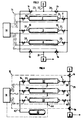
- the tank 1 of FIG. 1 comprises several containers 2, 3, 4 interconnected by a main pipe 5, each container being connected to the pipe 5 respectively by a pipe 6, 7, 8.
- Each container 2, 3, 4 is , for example, consisting of a tubular or cylindrical structure 9, (Fig. 2), manufactured according to patent FR-2,553,860 of the applicant, equipped at one of its ends with a nozzle provided with at least one opening and means 10 for closing or communicating with the outside allowing its connection respectively to the pipe 6, 7, 8 and at the other end of a bottom 11.
- the container is covered with means of resistance to longitudinal traction 12, surrounding the container with the exception of the openings.
- the means of communication between the containers and the outside are, for example, a valve or a plug such as those standardized for the storage of liquefied gases or compressed gases.
- the lines 6, 7, 8 comprise, for example, a valve V making it possible to isolate the containers 2, 3, 4 from the rest of the system.
- the main pipe 5 is connected to a distribution station S via a line 13 and a valve Vr allowing the filling of the various hydrocarbon containers to be controlled and, optionally, a valve Vd for distributing the hydrocarbons towards a device D, such as a pressure reducer, bringing the hydrocarbon to the intake pressure of the engine of the vehicle on which the tank is loaded, as is well known to specialists.
- a valve Vr, Vd are, for example, high pressure solenoid valves usually used for vehicles running on LPG or natural gas.
- the containers are equipped, for example, with conventional devices, not shown in the figure, such as an automatic filling stop device, a fuel level control gauge and a pressure sensor.
- the automatic filling stop device is adjusted with respect to a threshold value corresponding to a level of hydrocarbon in the container which it is preferable not to exceed, the threshold value being called in the following description of the threshold level of filling.
- valves V, and solenoid valves Vr, Vd are preferably connected to a microprocessor 14, by means of electrical connections 15.
- the cylindrical zone 9 (Fig. 2) of the container consists of an internal corrugated sheath 16 whose hollow portions 16a, 16b are filled with reinforcing fibers 17 over almost their entire height H. It is essential to fill the portions hollow, from the bottom (which corresponds to the external face of said sheath) to the zone where the radius of curvature of the external zone of the corrugation of the sheath becomes substantially constant (which corresponds to a variation of the radius curvature less than 10%).
- the corrugated sheath consists of successive circle portions 18, 19, which may or may not be separated by substantially rectilinear portions 20 seen in section, and corresponding to substantially frustoconical zones, in spatial representation.
- the shapes formed by the successive hollow and raised portions can constitute successive rings or adopt a helical shape.
- the longitudinal tensile strength means 12 arranged on the whole of the container may consist of fibers deposited on the whole of the external structure of the container with the exception of the openings.
- These longitudinal tensile strength means 12 or longitudinal reinforcement are preferably made of synthetic fibers, such as aramid, carbon or glass fibers, optionally impregnated with elastomer or thermoplastic resin. These fibers are put in place, for example, by winding or by placing a braid on the external structure. The aim being to resume the bottom effect of the cylindrical or tubular part of the container, any other means making it possible to obtain this result can also be used.
- the sheath is preferably made of metal such as aluminum or stainless steel.
- the sheath is made of thermoplastic polymer, such as high density polyethylene, optionally crosslinked, polypropylene, polyamides 6, 6.6, 11 or 12 or polyvinylidene fluoride which have, plus, good resistance and low permeability in contact with pressurized hydrocarbons.
- thermoplastic polymer such as high density polyethylene, optionally crosslinked, polypropylene, polyamides 6, 6.6, 11 or 12 or polyvinylidene fluoride which have, plus, good resistance and low permeability in contact with pressurized hydrocarbons.
- the reinforcing fibers forming the circumferential reinforcements consist of resin reinforced with fibers, for example glass or carbon, the resin being of the epoxy, polyester or vinyl ester type.
- the reinforcements can be made of any material allowing good resistance to circumferential pressure to be obtained.
- the entire cylindrical or tubular zone can be coated with an outer protective layer 21 obtained, for example, by extrusion of a thin layer of a thermoplastic, such as polyethylene or by helical winding of a strip of plastic or elastomeric material.
- This protective layer improves impact resistance; it makes it possible to distribute any external stresses over the entire structure and it protects the fibrous reinforcements against tearing.
- the filling of such a system can be done, for example, in the following way: one comes to connect the pipe 5 to the hydrocarbon distribution pipe 13, the end of the filling pipe being located at a location of the engine such that it prevents the vehicle from leaving the station if the pipe is not disconnected.
- Manually control or the microprocessor 14 controls the opening of the valve Vr, the valve Vd being closed and kept closed during the container filling operation.
- the valves V being in the open position, the hydrocarbon, for example pressurized natural gas coming from the distribution station S passes through the pipe 5 then is distributed indifferently in the pipes 6, 7, 8 opening into the various containers.
- the fuel level control gauge fitted to a container sends a signal to the automatic filling stop device which controls the closing of valve V of the container concerned as soon as the level of hydrocarbon reaches a threshold level fixed beforehand.
- the automatic filling stop device closes the various valves V, thus indicating that the tank is filled, and the microprocessor 14 controls the closing of the filling valve Vr.
- the vehicle is then disconnected from the distribution station by disconnecting line 5 from the filling station.
- the microprocessor 14 controls the openings of the valve Vd and of at least one of the valves V.
- the openings of these valves allow the passage of natural gas under pressure to the regulator D and the starting of the vehicle.
- the containers consist of a cylindrical zone, each end of which is provided with a nozzle comprising means 10 for communication.
- Containers can thus be connected by one end or by their two ends to pipes allowing the arrival of hydrocarbons.
- the reservoir 1 is connected to the hydrocarbon distribution station by means of a main pipe 22 dividing into two pipes 23, 24.
- the containers 2, 3, 4 are connected to the pipe 23 by secondary pipes 26, 28, 30 and to the pipe 24 by secondary pipes 25, 27, 29.
- the pipes 23 and 24 are grouped together in a single pipe 31 opening into the device D.
- the pipes 23 and 24 are provided with valves V1, V2 controlling the filling the containers with the hydrocarbon and valves V3, V4 which control the distribution of this hydrocarbon from the containers to the device D.
- the filling sequence of such a reservoir consists, for example, in connecting the line 22 to the distribution source S, then manually or through the microprocessor 14 to control the opening of the valves V1, V2, the valves V3, V4 being closed and kept closed during the container filling operation.
- the pressurized natural gas passes through the pipe 22, then is distributed indifferently in the pipes 25, .... 30 according to the state of the valves V, authorizing or not the passage of the gas towards the containers.
- the fuel level control gauges fitted to the containers send a signal to the automatic filling stop device so that the latter controls the closing of the valves V as soon as the filling level is reached in a container.
- the microprocessor 14 closes the valves V1, V2, then disconnects the line 5 from the filling station.
- FIG. 3 Another way of exploiting the embodiment described in FIG. 3 consists in using one of the lateral pipes, for example 23 for filling the containers and the other pipe 24 for discharging at least part of the gas from the containers to the regulator D.
- the lines 22 and 31 are no longer part of the device.
- the lines 23 and 24 respectively serve as filling lines and gas discharge lines, these two lines are then connected directly to the filling station S and to the pressure reducer D.
- the advantage of this device lies mainly in the simplification of the manufacture of tubular or cylindrical tanks comprising a nozzle placed at each end of the reinforced tubular structure and in the reliability of the tanks thus obtained which no longer have a bottom, for example hemispherical .
- a particularly advantageous embodiment of the system according to the invention consists in increasing the safety and the reliability of the hydrocarbon storage systems on board commercial vehicles.
- the reservoirs according to the invention are more flexible than the lightened reservoirs proposed according to the prior art; they therefore have better resistance to deformation in the event of accidental impact.
- FIG. 4 describes a hydrocarbon storage tank comprising an auxiliary container whose function is to recover the gas escaping from at least one of the containers making up the tank.
- the tank 1 consists of several containers 32, 33, 34 connected to a main supply line 35 by means of secondary lines 36, 38 and 40 situated at a first end of the containers and by means of secondary lines 37 , 39, 41 situated at their second end to a safety pipe 42 opening into an auxiliary container 43.
- Each container is equipped with an alarm device 44 capable of detecting a failure occurring in the container.
- This device is for example a pressure sensor, connected to the microprocessor by an electrical link 15.
- the sensor indicates to the microprocessor the variation over time of the pressure value measured in a container and the measured pressure value can be compared with values thresholds set beforehand, corresponding to alarm values, for example, a low pressure value in the container or an abnormal variation in time of the pressure value can translate a gas leak for one of the containers.
- the main pipe 35 is equipped with a valve Vr for filling the hydrocarbons from the distribution station S.
- the secondary pipes 36, 38 and 40 are each equipped with a valve V such as those described in FIG. 1 making it possible to control the filling of each of the containers 32, 33, 34.
- the secondary lines 37, 39, 41 are equipped with valves, called safety valves, Vs, having the role of allowing the hydrocarbon to pass to the auxiliary container 43 in the event of deterioration or rupture of one of the containers.
- Vs safety valves
- These valves are, for example, identical to the valves V and are connected by electrical connections 15 to the microprocessor 14.
- the auxiliary container 43 has a structure identical to that of the containers 32, 33, 34, for the sake of uniformity of the system.
- this container is chosen to be smaller than those of the storage containers constituting the reservoir since only part of the leaking gas is recovered.
- Such a system can operate in the following way: the pressure sensor 44 located, for example, in the container 32 sends to the microprocessor 14 a signal indicating an abnormal pressure variation and a pressure value below a threshold value. This signal is taken into account by the microprocessor 14 which then controls the opening of the valve Vs of the pipe 37 so as to allow the hydrocarbon from the container 32 to pass through the pipe 42 opening into the auxiliary container 43. The passage of gas is done until the measured pressure value is substantially zero. The microprocessor 14 then isolates the container from the rest of the system by closing the appropriate valves V and Vs.
- the gas evacuation pipe 42 is equipped with a device making it possible to force the passage of the gas towards the auxiliary container, this device being located near the end of the auxiliary container.
- One of the advantages offered by this system is to minimize the amount of gas escaping into nature and thus reduce the risk of explosion and pollution, by recovering the gas in an auxiliary container.
- all of the containers and pipes through which the hydrocarbons or gas under pressure pass is preferably placed in a protective envelope 45 (FIG. 5), made for example of plastic material, aluminum or composite material.
- a protective envelope 45 (FIG. 5)
- the space between the envelope and the containers, as well as the various pipes is filled, for example, by a cellular material 46, such as a polyurethane foam.
- This space can also be filled with a material exhibiting good behavior in the event of ignition of the hydrocarbon, such as an expandable composition based on phenolic resin.
- the envelope and material assembly constitutes a protective envelope against shocks and overheating of the assembly.
- Fire protection walls can also be placed between the containers.
- the containers are individually surrounded by a material resistant to impact and fire.
- the arrangement of the containers and the associated supply system result in a light tank which can be easily loaded on transport of utility type or on vehicles of heavy truck type and placed in any vehicle location.
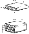
- the reservoir of FIG. 5A consists of a layer of containers arranged in parallel, the reservoir is placed in an envelope 45 and on the roof of a vehicle.
- FIG. 5B shows a storage tank in its final use composed of several layers of containers preferably arranged in staggered rows, placed in an envelope 45, the assembly being positioned on the roof of the vehicle.
- This embodiment makes it possible to increase the storage capacity of the hydrocarbon while reducing the space occupied by the tank.
- the mass of the tank thus formed is less than 0.5 kg / liter of gaseous fuel and preferably between 0.3 and 0.4 kg / liter, while the mass of the tanks conventional cited in the prior art steel is between 0.85 and 1.05 kg / liter of gas while that of hooped or self-fretted metal tanks is between 0.65 and 0.70 kg / l.
- the tank according to the invention can be used for the storage of any type of pressurized fluid, more particularly substitution hydrocarbons such as liquefied petroleum (abbreviated as LPG), methane, ethane, propane, butane and natural gas.
- LPG liquefied petroleum
- the tank in the boot of a vehicle. It can be positioned horizontally or vertically.
- each tank being, for example, suitable for the storage of a given hydrocarbon.
Landscapes
- Engineering & Computer Science (AREA)
- Mechanical Engineering (AREA)
- General Engineering & Computer Science (AREA)
- Life Sciences & Earth Sciences (AREA)
- Sustainable Development (AREA)
- Sustainable Energy (AREA)
- Chemical & Material Sciences (AREA)
- Combustion & Propulsion (AREA)
- Transportation (AREA)
- Filling Or Discharging Of Gas Storage Vessels (AREA)
- Cooling, Air Intake And Gas Exhaust, And Fuel Tank Arrangements In Propulsion Units (AREA)
Applications Claiming Priority (2)
| Application Number | Priority Date | Filing Date | Title |
|---|---|---|---|
| FR9307394A FR2706578B1 (fr) | 1993-06-18 | 1993-06-18 | Réservoir de stockage d'hydrocarbures sous pression. |
| FR9307394 | 1993-06-18 |
Publications (2)
| Publication Number | Publication Date |
|---|---|
| EP0629809A1 true EP0629809A1 (de) | 1994-12-21 |
| EP0629809B1 EP0629809B1 (de) | 1998-03-04 |
Family
ID=9448297
Family Applications (1)
| Application Number | Title | Priority Date | Filing Date |
|---|---|---|---|
| EP94401200A Expired - Lifetime EP0629809B1 (de) | 1993-06-18 | 1994-05-31 | Lagerbehälter für Kohlenwasserstoffe unter Druck |
Country Status (5)
| Country | Link |
|---|---|
| US (1) | US5615702A (de) |
| EP (1) | EP0629809B1 (de) |
| JP (1) | JPH07149156A (de) |
| DE (1) | DE69408731T2 (de) |
| FR (1) | FR2706578B1 (de) |
Cited By (5)
| Publication number | Priority date | Publication date | Assignee | Title |
|---|---|---|---|---|
| EP0743485A3 (de) * | 1995-05-17 | 1997-01-15 | Daimler Benz Ag | Vorrichtung zum Betanken von Gasflaschen eines gasbetriebenen Omnibusses |
| FR2794406A1 (fr) * | 1999-06-04 | 2000-12-08 | Renault | Agencement de dispositifs d'absorption de l'energie cinetique produit par un choc sur un reservoir |
| EP1559949A1 (de) * | 2004-01-28 | 2005-08-03 | Gaveco AB | Vorrichtung und Verfahren zur Betankung von gasbetriebenen Fahrzeugen und Fahrzeuggasbehältern |
| WO2012123283A1 (de) * | 2011-03-16 | 2012-09-20 | Messer Gaspack Gmbh | Anordnung zum speichern und entnehmen von komprimiertem gas |
| WO2023046381A1 (de) * | 2021-09-21 | 2023-03-30 | Siemens Mobility GmbH | Tank für brennbare flüssigkeiten und gase |
Families Citing this family (32)
| Publication number | Priority date | Publication date | Assignee | Title |
|---|---|---|---|---|
| US5821406A (en) * | 1997-02-27 | 1998-10-13 | Koch Industries, Inc. | Crude oil measurement system and method |
| KR100325737B1 (ko) * | 1999-06-17 | 2002-03-06 | 류정열 | 엘피지용 차량의 다열 일체형 연료탱크연결구조 |
| US6112760A (en) * | 1999-09-20 | 2000-09-05 | Fab Industries, L.L.C. | Pressure relief system |
| JP2003276456A (ja) * | 2002-03-22 | 2003-09-30 | Honda Motor Co Ltd | 燃料タンク構造 |
| US7624753B2 (en) * | 2004-08-10 | 2009-12-01 | Gm Global Technology Operations, Inc. | Container for gas storage tanks in a vehicle |
| JP4602721B2 (ja) * | 2004-09-10 | 2010-12-22 | アネスト岩田株式会社 | 圧縮気体装置 |
| US20080041068A1 (en) * | 2006-08-19 | 2008-02-21 | Horton Edward E | Liquefied natural gas re-gasification and storage unit |
| US7654279B2 (en) * | 2006-08-19 | 2010-02-02 | Agr Deepwater Development Systems, Inc. | Deep water gas storage system |
| US8020722B2 (en) * | 2007-08-20 | 2011-09-20 | Richards Kevin W | Seamless multi-section pressure vessel |
| FR2936784B1 (fr) * | 2008-10-08 | 2010-10-08 | Gaztransp Et Technigaz | Cuve a membrane ondulee renforcee |
| US8443820B2 (en) * | 2009-06-03 | 2013-05-21 | Ford Global Technologies, Llc | Fuel distribution in multi-fuel tank compressed gas fuel systems |
| FR2955569B1 (fr) * | 2010-01-28 | 2012-01-20 | Arkema France | Dispositif constitue de futs connectes destine au transport de matieres dangereuses |
| CN102770574B (zh) * | 2010-02-24 | 2016-03-09 | 贝伦诺斯清洁电力控股有限公司 | 用于高压介质的自监测复合容器 |
| US9435489B2 (en) * | 2010-02-24 | 2016-09-06 | Hydrexia Pty Ltd | Hydrogen release system |
| JP5327382B2 (ja) * | 2010-05-06 | 2013-10-30 | トヨタ自動車株式会社 | 水素充填システム |
| US8903630B2 (en) | 2012-02-08 | 2014-12-02 | Ford Global Technologies, Llc | Method and system for engine control |
| US8919325B2 (en) | 2012-02-08 | 2014-12-30 | Ford Global Technologies, Llc | Method and system for engine control |
| US9115653B2 (en) | 2012-03-27 | 2015-08-25 | Ford Global Technologies, Llc | System and method for emptying a tank |
| US9422900B2 (en) | 2012-03-27 | 2016-08-23 | Ford Global Technologies, Llc | System and method for closing a tank valve |
| EP2650586B1 (de) | 2012-04-11 | 2015-02-25 | Magna Steyr Fahrzeugtechnik AG & Co KG | Druckspeicher mit einer Verbindungsvorrichtung |
| DE102012218857A1 (de) * | 2012-10-16 | 2014-04-17 | Bayerische Motoren Werke Aktiengesellschaft | Verfahren zum Befüllen einer Kraftstoffspeicheranlage eines Kraftfahrzeugs |
| US9086040B2 (en) * | 2012-10-17 | 2015-07-21 | Ford Global Technologies, Llc | Fuel system degradation test using two fuel tanks |
| US9528472B2 (en) | 2013-04-19 | 2016-12-27 | Ford Global Technologies, Llc | Enhanced fuel injection based on choke flow rate |
| US9366203B2 (en) * | 2013-09-24 | 2016-06-14 | Fca Us Llc | Conformable high pressure gaseous fuel storage system having a gas storage vessel with fractal geometry |
| FR3030013B1 (fr) * | 2014-12-12 | 2017-07-21 | Edmond Emile Thuries | Reservoir pour fluides sous pression compose de tubes de petit diametre |
| DE102016214680A1 (de) * | 2016-08-08 | 2018-02-08 | Bayerische Motoren Werke Aktiengesellschaft | Verfahren zum Einstellen der Temperatur und/oder des Drucks von Brennstoff, insbesondere von Wasserstoff, in mehreren Druckbehältern eines Fahrzeugs auf jeweils einen Temperatursollwert und/oder jeweils einen Drucksollwert vor einem Befüllungsvorgang der Druckbehälter |
| DE102016220259A1 (de) * | 2016-10-17 | 2018-04-19 | Robert Bosch Gmbh | Verfahren zum Betrieb einer Tankanlage |
| RU2682465C1 (ru) * | 2018-06-22 | 2019-03-19 | Игорь Анатольевич Мнушкин | Многотопливная система подготовки топливного газа для питания газового двигателя внутреннего сгорания |
| JP7615041B2 (ja) * | 2019-03-05 | 2025-01-16 | リナマー・コーポレーション | タイプiv圧力容器内の波形管の破損を防ぐ方法 |
| US11649927B2 (en) * | 2020-01-30 | 2023-05-16 | Toyota Motor Engineering & Manufacturing North America, Inc. | Dual-inlet valve refilling of a single fuel cylinder |
| US12181901B2 (en) * | 2020-11-03 | 2024-12-31 | Ideal Completion Services Llc | Automated tank systems and methods for use in oil and gas extraction operation |
| CN114110431B (zh) * | 2021-11-16 | 2023-07-18 | 华海(北京)科技股份有限公司 | 一种集成空压站节能供气系统及其调控方法 |
Citations (5)
| Publication number | Priority date | Publication date | Assignee | Title |
|---|---|---|---|---|
| GB532208A (en) * | 1939-08-22 | 1941-01-20 | Brockhouse J & Co Ltd | An improved gas storage system |
| CA1208742A (en) * | 1983-03-17 | 1986-07-29 | Gary T. Benner | Gas cylinder charging apparatus |
| GB2200198A (en) * | 1987-01-23 | 1988-07-27 | Boc Group Plc | Gas cylinder filling apparatus |
| DE3743804A1 (de) * | 1987-12-23 | 1989-07-06 | Man Nutzfahrzeuge Gmbh | Gasbetriebener omnibus |
| FR2672370A1 (fr) * | 1991-02-01 | 1992-08-07 | Inst Francais Du Petrole | Procede de fabrication d'une structure legere par expansion d'un reservoir metallique dans un tube ondule arme. |
Family Cites Families (5)
| Publication number | Priority date | Publication date | Assignee | Title |
|---|---|---|---|---|
| NO148481C (no) * | 1980-07-08 | 1983-10-19 | Moss Rosenberg Verft As | Fremgangsmaate ved transport av olje og gass under hoeyt trykk i tanker ombord i et skip |
| FR2600747B1 (fr) * | 1986-06-30 | 1988-12-30 | Inst Francais Du Petrole | Tube flexible utilisable notamment pour le transport de fluides caloporteurs ou frigorifiques |
| FR2661477B1 (fr) * | 1990-04-26 | 1992-07-10 | Inst Francais Du Petrole | Procede de fabrication d'une structure creuse utilisable notamment pour le stockage de fluides sous pression et structure resultante. |
| FR2669396B1 (fr) * | 1990-11-19 | 1997-05-09 | Inst Francais Du Petrole | Reservoir de poids unitaire faible utilisable notamment pour le stockage de fluides sous pression et son procede de fabrication. |
| US5246044A (en) * | 1991-02-20 | 1993-09-21 | Environmental Protection Products, Inc. | Fuel dispenser pump containment apparatus |
-
1993
- 1993-06-18 FR FR9307394A patent/FR2706578B1/fr not_active Expired - Lifetime
-
1994
- 1994-05-31 DE DE69408731T patent/DE69408731T2/de not_active Expired - Fee Related
- 1994-05-31 EP EP94401200A patent/EP0629809B1/de not_active Expired - Lifetime
- 1994-06-17 JP JP15951394A patent/JPH07149156A/ja active Pending
- 1994-06-20 US US08/262,608 patent/US5615702A/en not_active Expired - Fee Related
Patent Citations (5)
| Publication number | Priority date | Publication date | Assignee | Title |
|---|---|---|---|---|
| GB532208A (en) * | 1939-08-22 | 1941-01-20 | Brockhouse J & Co Ltd | An improved gas storage system |
| CA1208742A (en) * | 1983-03-17 | 1986-07-29 | Gary T. Benner | Gas cylinder charging apparatus |
| GB2200198A (en) * | 1987-01-23 | 1988-07-27 | Boc Group Plc | Gas cylinder filling apparatus |
| DE3743804A1 (de) * | 1987-12-23 | 1989-07-06 | Man Nutzfahrzeuge Gmbh | Gasbetriebener omnibus |
| FR2672370A1 (fr) * | 1991-02-01 | 1992-08-07 | Inst Francais Du Petrole | Procede de fabrication d'une structure legere par expansion d'un reservoir metallique dans un tube ondule arme. |
Cited By (8)
| Publication number | Priority date | Publication date | Assignee | Title |
|---|---|---|---|---|
| EP0743485A3 (de) * | 1995-05-17 | 1997-01-15 | Daimler Benz Ag | Vorrichtung zum Betanken von Gasflaschen eines gasbetriebenen Omnibusses |
| FR2794406A1 (fr) * | 1999-06-04 | 2000-12-08 | Renault | Agencement de dispositifs d'absorption de l'energie cinetique produit par un choc sur un reservoir |
| EP1559949A1 (de) * | 2004-01-28 | 2005-08-03 | Gaveco AB | Vorrichtung und Verfahren zur Betankung von gasbetriebenen Fahrzeugen und Fahrzeuggasbehältern |
| WO2012123283A1 (de) * | 2011-03-16 | 2012-09-20 | Messer Gaspack Gmbh | Anordnung zum speichern und entnehmen von komprimiertem gas |
| CN103502719A (zh) * | 2011-03-16 | 2014-01-08 | 梅塞尔气体设备有限公司 | 用于储存和抽取压缩气体的安排 |
| EP2686602B1 (de) | 2011-03-16 | 2015-06-17 | Messer GasPack GmbH | Anordnung zum speichern und entnehmen von komprimiertem gas |
| CN103502719B (zh) * | 2011-03-16 | 2015-10-21 | 梅塞尔气体设备有限公司 | 用于储存和抽取压缩气体的安排 |
| WO2023046381A1 (de) * | 2021-09-21 | 2023-03-30 | Siemens Mobility GmbH | Tank für brennbare flüssigkeiten und gase |
Also Published As
| Publication number | Publication date |
|---|---|
| DE69408731T2 (de) | 1998-06-25 |
| JPH07149156A (ja) | 1995-06-13 |
| DE69408731D1 (de) | 1998-04-09 |
| FR2706578A1 (fr) | 1994-12-23 |
| EP0629809B1 (de) | 1998-03-04 |
| US5615702A (en) | 1997-04-01 |
| FR2706578B1 (fr) | 1995-09-01 |
Similar Documents
| Publication | Publication Date | Title |
|---|---|---|
| EP0629809B1 (de) | Lagerbehälter für Kohlenwasserstoffe unter Druck | |
| US5499739A (en) | Thermoplastic liner for and method of overwrapping high pressure vessels | |
| CA2845724C (en) | Method of fabricating type 4 cylinders and arranging in transportation housings for transport of gaseous fluids | |
| EP3472509B1 (de) | Gaskuppelstruktur für ein abgedichtetes, wärmeisoliertes gefäss | |
| JP7341894B2 (ja) | 圧縮天然ガスの貯蔵及び輸送システム | |
| US20080127654A1 (en) | Container for Transport and Storage for Compressed Natural Gas | |
| EP4004427B1 (de) | Druckgasabgabevorrichtung | |
| KR20140115310A (ko) | 초고압 작동 압력 용기 | |
| FR2838177A1 (fr) | Reservoir pour fluide sous pression, notamment reservoir pour gaz comprime destine a un vehicule automobile | |
| EP2949449B1 (de) | Tank zum lagern von flüssigen oder gasförmigen medien, die unter druck stehen, und sein herstellungsverfahren | |
| WO2021255000A1 (fr) | Dôme liquide d'une cuve de stockage pour gaz liquéfié | |
| EP1067300B1 (de) | Vorratsbehälter aus Verbundmaterial zur Speicherung von unter Druck stehendem Flüssiggas | |
| WO2009129530A1 (en) | Composite structure vessel and transportation system for liquefied gases | |
| FR2720142A1 (fr) | Structure légère PA-12-carbone pour le stockage de fluides sous pression. | |
| EP1409917A1 (de) | Behälter für druckflüssigkeiten und dessen herstellungsverfharen | |
| EP4295045A1 (de) | Vorrichtung zum komprimieren eines in form einer kryogenen flüssigkeit gespeicherten fluids und zugehöriges herstellungsverfahren | |
| WO2021144531A1 (fr) | Double trappe d'accès pour une cuve de transport de gaz liquéfié | |
| FR3111411A1 (fr) | Dôme liquide d’une cuve de stockage pour gaz liquéfié | |
| EP4198375A1 (de) | Anlage zur lagerung eines flüssiggases mit einem behälter und einer domstruktur | |
| EP1679468A1 (de) | Gasdruckbehälter | |
| WO2022008432A1 (fr) | Installation de stockage pour un gaz liquéfié et/ou un liquide dangereux | |
| FR3030013A1 (fr) | Reservoir pour fluides sous pression compose de tubes de petit diametre | |
| FR2887611A1 (fr) | Reservoir en acier frette pour contenir un fluide sous pression | |
| BG4196U1 (bg) | Бутилка за газ |
Legal Events
| Date | Code | Title | Description |
|---|---|---|---|
| PUAI | Public reference made under article 153(3) epc to a published international application that has entered the european phase |
Free format text: ORIGINAL CODE: 0009012 |
|
| 17P | Request for examination filed |
Effective date: 19940613 |
|
| AK | Designated contracting states |
Kind code of ref document: A1 Designated state(s): DE GB IT NL |
|
| 17Q | First examination report despatched |
Effective date: 19960718 |
|
| GRAG | Despatch of communication of intention to grant |
Free format text: ORIGINAL CODE: EPIDOS AGRA |
|
| GRAG | Despatch of communication of intention to grant |
Free format text: ORIGINAL CODE: EPIDOS AGRA |
|
| GRAH | Despatch of communication of intention to grant a patent |
Free format text: ORIGINAL CODE: EPIDOS IGRA |
|
| GRAH | Despatch of communication of intention to grant a patent |
Free format text: ORIGINAL CODE: EPIDOS IGRA |
|
| GRAA | (expected) grant |
Free format text: ORIGINAL CODE: 0009210 |
|
| AK | Designated contracting states |
Kind code of ref document: B1 Designated state(s): DE GB IT NL |
|
| PG25 | Lapsed in a contracting state [announced via postgrant information from national office to epo] |
Ref country code: NL Free format text: LAPSE BECAUSE OF FAILURE TO SUBMIT A TRANSLATION OF THE DESCRIPTION OR TO PAY THE FEE WITHIN THE PRESCRIBED TIME-LIMIT Effective date: 19980304 Ref country code: IT Free format text: LAPSE BECAUSE OF FAILURE TO SUBMIT A TRANSLATION OF THE DESCRIPTION OR TO PAY THE FEE WITHIN THE PRESCRIBED TIME-LIMIT;WARNING: LAPSES OF ITALIAN PATENTS WITH EFFECTIVE DATE BEFORE 2007 MAY HAVE OCCURRED AT ANY TIME BEFORE 2007. THE CORRECT EFFECTIVE DATE MAY BE DIFFERENT FROM THE ONE RECORDED. Effective date: 19980304 |
|
| GBT | Gb: translation of ep patent filed (gb section 77(6)(a)/1977) |
Effective date: 19980305 |
|
| REF | Corresponds to: |
Ref document number: 69408731 Country of ref document: DE Date of ref document: 19980409 |
|
| NLV1 | Nl: lapsed or annulled due to failure to fulfill the requirements of art. 29p and 29m of the patents act | ||
| PLBE | No opposition filed within time limit |
Free format text: ORIGINAL CODE: 0009261 |
|
| STAA | Information on the status of an ep patent application or granted ep patent |
Free format text: STATUS: NO OPPOSITION FILED WITHIN TIME LIMIT |
|
| 26N | No opposition filed | ||
| PGFP | Annual fee paid to national office [announced via postgrant information from national office to epo] |
Ref country code: GB Payment date: 20000425 Year of fee payment: 7 |
|
| PGFP | Annual fee paid to national office [announced via postgrant information from national office to epo] |
Ref country code: DE Payment date: 20000605 Year of fee payment: 7 |
|
| PG25 | Lapsed in a contracting state [announced via postgrant information from national office to epo] |
Ref country code: GB Free format text: LAPSE BECAUSE OF NON-PAYMENT OF DUE FEES Effective date: 20010531 |
|
| GBPC | Gb: european patent ceased through non-payment of renewal fee |
Effective date: 20010531 |
|
| PG25 | Lapsed in a contracting state [announced via postgrant information from national office to epo] |
Ref country code: DE Free format text: LAPSE BECAUSE OF NON-PAYMENT OF DUE FEES Effective date: 20020301 |