EP0630155A2 - Gerät zur Aufzeichnung von digitalen Signalen - Google Patents
Gerät zur Aufzeichnung von digitalen Signalen Download PDFInfo
- Publication number
- EP0630155A2 EP0630155A2 EP94109198A EP94109198A EP0630155A2 EP 0630155 A2 EP0630155 A2 EP 0630155A2 EP 94109198 A EP94109198 A EP 94109198A EP 94109198 A EP94109198 A EP 94109198A EP 0630155 A2 EP0630155 A2 EP 0630155A2
- Authority
- EP
- European Patent Office
- Prior art keywords
- data
- block
- recording
- sequence number
- information
- Prior art date
- Legal status (The legal status is an assumption and is not a legal conclusion. Google has not performed a legal analysis and makes no representation as to the accuracy of the status listed.)
- Granted
Links
Images


Classifications
-
- G—PHYSICS
- G11—INFORMATION STORAGE
- G11B—INFORMATION STORAGE BASED ON RELATIVE MOVEMENT BETWEEN RECORD CARRIER AND TRANSDUCER
- G11B20/00—Signal processing not specific to the method of recording or reproducing; Circuits therefor
- G11B20/10—Digital recording or reproducing
-
- H—ELECTRICITY
- H04—ELECTRIC COMMUNICATION TECHNIQUE
- H04N—PICTORIAL COMMUNICATION, e.g. TELEVISION
- H04N21/00—Selective content distribution, e.g. interactive television or video on demand [VOD]
- H04N21/20—Servers specifically adapted for the distribution of content, e.g. VOD servers; Operations thereof
- H04N21/23—Processing of content or additional data; Elementary server operations; Server middleware
- H04N21/236—Assembling of a multiplex stream, e.g. transport stream, by combining a video stream with other content or additional data, e.g. inserting a URL [Uniform Resource Locator] into a video stream, multiplexing software data into a video stream; Remultiplexing of multiplex streams; Insertion of stuffing bits into the multiplex stream, e.g. to obtain a constant bit-rate; Assembling of a packetised elementary stream
-
- G—PHYSICS
- G11—INFORMATION STORAGE
- G11B—INFORMATION STORAGE BASED ON RELATIVE MOVEMENT BETWEEN RECORD CARRIER AND TRANSDUCER
- G11B27/00—Editing; Indexing; Addressing; Timing or synchronising; Monitoring; Measuring tape travel
- G11B27/02—Editing, e.g. varying the order of information signals recorded on, or reproduced from, record carriers
- G11B27/031—Electronic editing of digitised analogue information signals, e.g. audio or video signals
- G11B27/032—Electronic editing of digitised analogue information signals, e.g. audio or video signals on tapes
-
- G—PHYSICS
- G11—INFORMATION STORAGE
- G11B—INFORMATION STORAGE BASED ON RELATIVE MOVEMENT BETWEEN RECORD CARRIER AND TRANSDUCER
- G11B27/00—Editing; Indexing; Addressing; Timing or synchronising; Monitoring; Measuring tape travel
- G11B27/10—Indexing; Addressing; Timing or synchronising; Measuring tape travel
- G11B27/19—Indexing; Addressing; Timing or synchronising; Measuring tape travel by using information detectable on the record carrier
- G11B27/28—Indexing; Addressing; Timing or synchronising; Measuring tape travel by using information detectable on the record carrier by using information signals recorded by the same method as the main recording
- G11B27/30—Indexing; Addressing; Timing or synchronising; Measuring tape travel by using information detectable on the record carrier by using information signals recorded by the same method as the main recording on the same track as the main recording
- G11B27/3027—Indexing; Addressing; Timing or synchronising; Measuring tape travel by using information detectable on the record carrier by using information signals recorded by the same method as the main recording on the same track as the main recording used signal is digitally coded
-
- H—ELECTRICITY
- H04—ELECTRIC COMMUNICATION TECHNIQUE
- H04N—PICTORIAL COMMUNICATION, e.g. TELEVISION
- H04N21/00—Selective content distribution, e.g. interactive television or video on demand [VOD]
- H04N21/40—Client devices specifically adapted for the reception of or interaction with content, e.g. set-top-box [STB]; Operations thereof
- H04N21/43—Processing of content or additional data, e.g. demultiplexing additional data from a digital video stream; Elementary client operations, e.g. monitoring of home network or synchronising decoder's clock; Client middleware
- H04N21/434—Disassembling of a multiplex stream, e.g. demultiplexing audio and video streams, extraction of additional data from a video stream; Remultiplexing of multiplex streams; Extraction or processing of SI; Disassembling of packetised elementary stream
-
- H—ELECTRICITY
- H04—ELECTRIC COMMUNICATION TECHNIQUE
- H04N—PICTORIAL COMMUNICATION, e.g. TELEVISION
- H04N5/00—Details of television systems
- H04N5/76—Television signal recording
- H04N5/91—Television signal processing therefor
- H04N5/92—Transformation of the television signal for recording, e.g. modulation, frequency changing; Inverse transformation for playback
- H04N5/926—Transformation of the television signal for recording, e.g. modulation, frequency changing; Inverse transformation for playback by pulse code modulation
- H04N5/9261—Transformation of the television signal for recording, e.g. modulation, frequency changing; Inverse transformation for playback by pulse code modulation involving data reduction
-
- H—ELECTRICITY
- H04—ELECTRIC COMMUNICATION TECHNIQUE
- H04N—PICTORIAL COMMUNICATION, e.g. TELEVISION
- H04N5/00—Details of television systems
- H04N5/76—Television signal recording
- H04N5/91—Television signal processing therefor
- H04N5/92—Transformation of the television signal for recording, e.g. modulation, frequency changing; Inverse transformation for playback
- H04N5/926—Transformation of the television signal for recording, e.g. modulation, frequency changing; Inverse transformation for playback by pulse code modulation
- H04N5/9265—Transformation of the television signal for recording, e.g. modulation, frequency changing; Inverse transformation for playback by pulse code modulation with processing of the sound signal
- H04N5/9267—Transformation of the television signal for recording, e.g. modulation, frequency changing; Inverse transformation for playback by pulse code modulation with processing of the sound signal using time division multiplex of the PCM audio and PCM video signals
- H04N5/9268—Transformation of the television signal for recording, e.g. modulation, frequency changing; Inverse transformation for playback by pulse code modulation with processing of the sound signal using time division multiplex of the PCM audio and PCM video signals with insertion of the PCM audio signals in the vertical blanking interval of the PCM video signal
-
- G—PHYSICS
- G11—INFORMATION STORAGE
- G11B—INFORMATION STORAGE BASED ON RELATIVE MOVEMENT BETWEEN RECORD CARRIER AND TRANSDUCER
- G11B2220/00—Record carriers by type
- G11B2220/90—Tape-like record carriers
-
- H—ELECTRICITY
- H04—ELECTRIC COMMUNICATION TECHNIQUE
- H04N—PICTORIAL COMMUNICATION, e.g. TELEVISION
- H04N5/00—Details of television systems
- H04N5/76—Television signal recording
- H04N5/78—Television signal recording using magnetic recording
- H04N5/782—Television signal recording using magnetic recording on tape
- H04N5/783—Adaptations for reproducing at a rate different from the recording rate
-
- H—ELECTRICITY
- H04—ELECTRIC COMMUNICATION TECHNIQUE
- H04N—PICTORIAL COMMUNICATION, e.g. TELEVISION
- H04N5/00—Details of television systems
- H04N5/76—Television signal recording
- H04N5/91—Television signal processing therefor
- H04N5/93—Regeneration of the television signal or of selected parts thereof
- H04N5/94—Signal drop-out compensation
- H04N5/945—Signal drop-out compensation for signals recorded by pulse code modulation
Definitions
- the present invention relates to a digital signal recording apparatus and, more particularity, to a digital signal recording apparatus for recording digital audio and video signals.
- VCR Consumer-use digital Video Cassette Recorders for recording audio and video signals as digital signals are now commercially available.
- the consumer digital Video Cassette Recorder (VCR) market has been constrained by the various methods applying video compression (band width compression) technologies to the video signal that have been proposed as a means for reducing cassette size.
- Fig. 5A an example of the on-tape positioning of the video signals and audio signals recorded by a digital VCR is shown.
- the audio and video signals for one frame are recorded to ten tracks Tr0 to Tr9 on tape. It is to be noted that the audio and video signals are recorded to specific and different segments Sa and Sv of each track.
- each track Tr further comprises a plurality of recording blocks Br (Fig. 6) in the audio and video signal segments Sa and Sv.
- Each audio signal segment Sa is comprised of a predetermined number of audio data recording blocks Ba and parity recording blocks Bp.
- each video segment Sa is comprised of a predetermined number of video data recording blocks Bv and parity recording blocks Bp.
- the audio data recording block Ba, the video data recording block Bv, and the parity recording block Bp has principally the same construction of the recording block Br, as best shown in Fig. 6.
- the audio or video signals are divided into a plurality of small data blocks Db which is recorded in one recording block Br.
- Each data block Db is complemented by a synchronization signal Ds for bit synchronization, ID information indicating the location of the recording data block in the frame, and parity data Dp for error correction.
- parity recording blocks Bp only parity data is recorded in its data Db instead of video or audio signal data.
- those complementing information makes it possible to reproduce the original video signal and/or audio signal from the recorded data block Db in the recording blocks Br.
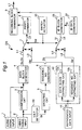
- the digital signal recording apparatus DR comprises an audio signal input 1 from which digital audio signal is input and a video signal input 2 from which the digital video signal is input.
- a compression circuit 3 is connected to the video data input 2 for compressing the audio signal to produce a compressed video data Sv.
- a data block generator 4 is connected to the compression circuit 3 and the audio data input 1.
- the data block generator 4 divides the compressed video data Sv into predetermined data blocks Db and produces an unit video data Sv, as previously described with reference to Fig. 6.
- the audio signal is divided into data blocks Db, and the unit audio signal Sa is produced.
- the unit data Sv and Sa are output through a line L1.
- a data switch 7 is provided for connecting the line L1 to a line L5 in response to a selection signal Sw from a switch actuator 13.
- the switch actuator 13 can be operated manually or automatically based on the operation mode, for example a normal recording or a data copying (dubbing the reproduced data), of the recording apparatus DR.
- An parity generator 8 is connected to the line L5 for producing the error correction parity data Dp (Fig. 6) based on each of unit video data Sv transferred therein, and adds thus produced parity data Dp to the unit video data Sv.
- the unit video data Sv is the data block Db, as described before.
- the error correction circuit 8 produces and adds the parity data Db to the unit audio data Sa (Db).
- the data block Db is complement by parity data Dp for the recording block Br.
- a recording block generator 9 is connected to the parity generator 8 for receiving video and audio data Sv and Sa comprising the parity data Dp and data block Db.
- a grouping circuit 5 is also connected to the video signal input 2 through a V.B.P detector 20 which detects the vertical blanking period from the video signal and produces a timing signal Sv.
- the grouping circuit 5 counts the number of frames in the Video signal based on the timing signal St, and forms groups from each continuous block of twelve frame periods.
- a sequence number generator 6 is connected to the grouping circuit 5 for dividing each group period into one sequence per frame. Each group is divided into twelve sequences.
- the sequence number generator 6 generates a sequence data Ss indicative of a sequence number for each sequence in order from the first sequence in one group, and outputs the sequence data Ss through a line 3.
- An ID switch 31 is provided for connecting the line L2 to a line L6 and is also actuated by the switch actuator, so that the sequence data Ss is transmitted to an ID block generator 23 which is connected to the line 6.
- An ID generator 24 is also connected to the ID block generator 23. The ID generator 24 determines the ID information indicating the number of track Tr and recording block Br wherein each data block Db is recorded, and produces an ID information data Si.
- the ID block generator 23 Based on the sequence data Ss and the ID information data Si, the ID block generator 23 produces the complete ID for each data block Db. It is to be noted that the ID produced here additionally includes the sequence data Ss of each data block Db. Thus, completed ID is transferred to the recording block generator 9.
- the recording block generator 9 adds the ID from the ID block generator 23 to the parity data added data block Db, and further adds synchronization signal Ds. Thus, the complete video or audio signal for one recording block Br is produced, and is transferred through a line L7 for recording on the recording tape.
- the recording apparatus DR further comprises a reproduced data input 11 from which reproduced digital signal Sr is input.
- Reproduced digital signal Sr comprises the data block Db, synchronization signal Ds, and the complete ID including the sequence Data, and parity data Dp which is completed by the recording block generator 9.
- a recording block reproducing unit 12 is comprised of a data block extracting circuit 12a and a sequence number extracting circuit 12b, and is connected to a reproduced data input 11. From the reproduced signal Sr, the data block extracting circuit 12a extracts the reproduced data block Db', which is output thorough a line L3. Similarly, the sequence number extracting circuit 12b extracts a reproduced sequence data Ss' indicative of the sequence number of the reproduced data block Db' which is output through a line L4.
- the switch actuator 13 actuates the switch 7 to connect the line L3 and the line L5, and actuates the switch 31 to connect the line L4 and the line L6.
- the reproduced data block Db' and sequence data Ss' are processed by the parity generator 8, recording block generator 9, and ID block generator 23 in cooperation of the ID data generator 24 for recording on tape, as described above.
- a sequence number identifying to which frame (sequence) the data block Db of the recording block Br belongs is added to each data block Db before recording when the video signal and audio signal are directly recorded. As a result, it can be determined to which frame each recording block belongs when the recording blocks are reproduced.
- the data of the reproduced recording blocks and the sequence numbers can be re-recorded directly.
- recording blocks of plural sequence numbers will be mixed together in one sequence period on tape.
- the sequence numbers are added to each recording block individually, the original recording block order can be reproduced as described above. Therefore, even data for which the time-based relationship is important, e.g., audio signal data, can be easily reproduced.
- one sequence period is one frame, and one group is twelve sequences, but it is also possible to otherwise set the size of one sequence period and one group period according to the input signal.
- this recording block may be related to the data of plural recording blocks.
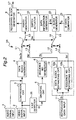
- a data information generator 33 is additionally provided and is connected to the ID block generator 23. This is because when the parity recording blocks Bp shown in Fig. 5B is reproduced, the data extracting circuit 12a does not extract the reproduced data Db' but the sequence extracting circuit 12b extracts the reproduced sequence number Ss'. In this case, a data type identification number, which indicates what type of data is recorded to the data area (the related recording block) to which the error correction code is related, is recorded to the recording area to which the sequence number of the recording block is recorded.
- the data information generator 33 produces a data signal Sd indicating these data types which is input to the ID block generator 23.
- the data information generator 33 can be operated manually or automatically.
- the data information generator 33 also produces a data signal Sd when the signals from audio and video signal inputs 1 and 2 are recorded in a manner as described the above.
- any of the signal inputs 1 or 2 actuates the data information generator 33 to produce the data signal Sd indicative of the kind of signals input thereto.
- the user may actuates the data information generator 33 according to the kind of singles for recording.
- a sequence error detector 15 is additionally provided on the line L4 after the sequence number extracting circuit 12b.
- the sequence error detector 15 determines whether the sequence number (Ss') of the recording blocks (Sr') input thereto from the sequence number extracting circuit 12b are correct.
- sequence number Ss' which is simultaneously reproduced with the data block are input to the ID block generator 23 through the line L4, the sequence switch 31, and the line L6.
- the data block Db' corresponding to this sequence number is also input to the parity generator 8 though the line L3 and switch 7.
- the sequence number assigned to recording blocks of which the sequence affiliation is not known is, for example, 15.
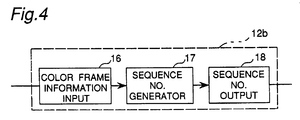
- the sequence number extracting circuit 12b comprises a color frame information input 16, a sequence number generator 17, and a sequence number output 18.
- phase (color frame) changes in a two frame cycle in the NTSC signal format, and changes in a four frame cycle in the PAL signal format. It is therefore necessary to simultaneously transmit the color frame if a composite TV signal is handled in frame units.
- the sequence number generator 17 shown in Fig. 4 generates a sequence number of which the low bit is the same as the color frame number input from the color frame information input 16, and outputs the result to the sequence number output 18.
- the low one bit of the sequence numbers in an NTSC signal are the same value as the color frame
- the low two bits of the sequence numbers in a PAL signal are the same value as the color frame.
- the color frame information is also important information for recording a composite TV signal separated into luminance signal and color difference signal components, and can also be used with a non-composite TV signal data processed on a plural frame cycle with the processing method differing on a frame basis.
- the present invention has been described above, but the method and construction of recording block grouping, error correction coding, and sequence number assignment can be varied in many ways from those described above.
- the above embodiment can also be combined in various ways, and can be achieved in software.
- the invention is also applicable to formats other than that of the prior art described above, and is furthermore applicable to recording data other than video signal and audio signal data.
- the present invention can reproduce data copied from variable speed reproduced data, and the practical utility of the invention is therefore great.
- the present invention can be applicable to any other digital recording medium then the digital VCR.
- any other recording medium than the tape such as an optical disk or a magnetic disk suitable for digital recording can be used in the recording apparatus according to the present invention.
Landscapes
- Engineering & Computer Science (AREA)
- Multimedia (AREA)
- Signal Processing (AREA)
- Signal Processing For Digital Recording And Reproducing (AREA)
- Television Signal Processing For Recording (AREA)
Applications Claiming Priority (3)
| Application Number | Priority Date | Filing Date | Title |
|---|---|---|---|
| JP144658/93 | 1993-06-16 | ||
| JP14465893 | 1993-06-16 | ||
| JP5144658A JP2630202B2 (ja) | 1993-06-16 | 1993-06-16 | 記録装置 |
Publications (3)
| Publication Number | Publication Date |
|---|---|
| EP0630155A2 true EP0630155A2 (de) | 1994-12-21 |
| EP0630155A3 EP0630155A3 (de) | 1995-04-19 |
| EP0630155B1 EP0630155B1 (de) | 2000-03-22 |
Family
ID=15367217
Family Applications (1)
| Application Number | Title | Priority Date | Filing Date |
|---|---|---|---|
| EP94109198A Expired - Lifetime EP0630155B1 (de) | 1993-06-16 | 1994-06-15 | Gerät zur Aufzeichnung von digitalen Signalen |
Country Status (5)
| Country | Link |
|---|---|
| US (1) | US5594550A (de) |
| EP (1) | EP0630155B1 (de) |
| JP (1) | JP2630202B2 (de) |
| KR (1) | KR100239624B1 (de) |
| DE (1) | DE69423540T2 (de) |
Cited By (3)
| Publication number | Priority date | Publication date | Assignee | Title |
|---|---|---|---|---|
| EP0701253A3 (de) * | 1994-08-10 | 1997-03-05 | Matsushita Electric Industrial Co Ltd | Aufzeichnungs- und Wiedergabegerät für kodierten Datenstrom |
| US6034547A (en) * | 1996-09-04 | 2000-03-07 | Advantage Logic, Inc. | Method and apparatus for universal program controlled bus |
| US6256449B1 (en) | 1996-07-01 | 2001-07-03 | Sony Corporation | Image encoder and image decoder |
Families Citing this family (6)
| Publication number | Priority date | Publication date | Assignee | Title |
|---|---|---|---|---|
| JP3460345B2 (ja) * | 1994-12-19 | 2003-10-27 | ソニー株式会社 | ビデオカメラシステム |
| DE69623771T2 (de) * | 1995-05-31 | 2003-07-31 | Sony Corp., Tokio/Tokyo | Verfahren und vorrichtung zur kodierung von audiosignalen und verfahren und vorrichtung zur dekodierung von audiosignalen |
| JPH09116866A (ja) * | 1995-10-20 | 1997-05-02 | Sony Corp | 符号化方法、符号化復号化方法及び記録再生装置 |
| WO2000019432A1 (en) | 1998-09-25 | 2000-04-06 | Matsushita Electric Industrial Co., Ltd. | Information recording medium, information recording/reproducing method, and information recording/reproducing device |
| US6473875B1 (en) * | 1999-03-03 | 2002-10-29 | Intel Corporation | Error correction for network delivery of video streams using packet resequencing |
| KR102378500B1 (ko) * | 2019-09-17 | 2022-03-24 | 이현수 | 환편기용 실공급량 측정장치 |
Family Cites Families (8)
| Publication number | Priority date | Publication date | Assignee | Title |
|---|---|---|---|---|
| JP2526875B2 (ja) * | 1986-11-05 | 1996-08-21 | ソニー株式会社 | デイジタル情報記録装置 |
| JP2900385B2 (ja) * | 1988-12-16 | 1999-06-02 | ソニー株式会社 | フレーム化回路及び方法 |
| JPH02284583A (ja) * | 1989-04-26 | 1990-11-21 | Ricoh Co Ltd | 情報挿入装置 |
| JP2540985B2 (ja) * | 1990-05-29 | 1996-10-09 | 三菱電機株式会社 | デイジタル画面デ―タの記録方式 |
| CA2335403C (en) * | 1990-06-05 | 2002-03-19 | Koninklijke Philips Electronics N.V. | Optical readable disc storing full-motion video scene |
| US5347406A (en) * | 1990-10-31 | 1994-09-13 | Sony Corporation | Digital video recording apparatus for recording digital video signals of reduced bit rate on magnetic tape having particular thickness, energy product and surface roughness |
| JPH04209384A (ja) * | 1990-11-30 | 1992-07-30 | Sharp Corp | 磁気テープ記録/再生装置 |
| JP2708312B2 (ja) * | 1992-03-05 | 1998-02-04 | 松下電器産業株式会社 | 記録装置及び再生装置 |
-
1993
- 1993-06-16 JP JP5144658A patent/JP2630202B2/ja not_active Expired - Fee Related
-
1994
- 1994-06-14 US US08/261,044 patent/US5594550A/en not_active Expired - Fee Related
- 1994-06-15 EP EP94109198A patent/EP0630155B1/de not_active Expired - Lifetime
- 1994-06-15 KR KR1019940013431A patent/KR100239624B1/ko not_active Expired - Fee Related
- 1994-06-15 DE DE69423540T patent/DE69423540T2/de not_active Expired - Fee Related
Cited By (4)
| Publication number | Priority date | Publication date | Assignee | Title |
|---|---|---|---|---|
| EP0701253A3 (de) * | 1994-08-10 | 1997-03-05 | Matsushita Electric Industrial Co Ltd | Aufzeichnungs- und Wiedergabegerät für kodierten Datenstrom |
| US5841941A (en) * | 1994-08-10 | 1998-11-24 | Matsushita Electric Indstrial Co., Ltd. | Encoded data stream recording and reproducing apparatus with tape speed, channel number, and cylinder speed control in accordance with bit rate |
| US6256449B1 (en) | 1996-07-01 | 2001-07-03 | Sony Corporation | Image encoder and image decoder |
| US6034547A (en) * | 1996-09-04 | 2000-03-07 | Advantage Logic, Inc. | Method and apparatus for universal program controlled bus |
Also Published As
| Publication number | Publication date |
|---|---|
| US5594550A (en) | 1997-01-14 |
| JPH0723327A (ja) | 1995-01-24 |
| EP0630155B1 (de) | 2000-03-22 |
| DE69423540D1 (de) | 2000-04-27 |
| KR950001717A (ko) | 1995-01-03 |
| KR100239624B1 (ko) | 2000-01-15 |
| JP2630202B2 (ja) | 1997-07-16 |
| DE69423540T2 (de) | 2000-11-09 |
| EP0630155A3 (de) | 1995-04-19 |
Similar Documents
| Publication | Publication Date | Title |
|---|---|---|
| KR100811962B1 (ko) | 기록 장치 및 기록 방법, 재생 장치 및 재생 방법과 그기록 매체 | |
| EP0520444A2 (de) | Verfahren und Vorrichtung zur Aufzeichnung komprimierter Audiodaten auf einem Videoaufzeichnungsträger | |
| US5594550A (en) | Digital signal recording apparatus for recording digital data comprising a plurality of recording blocks | |
| EP0408343B1 (de) | Kodierung- und Dekodierungsvorrichtung geeignet für das Kopieren von Daten | |
| JPH01202994A (ja) | カラー画像データ伝送方法 | |
| US6421091B1 (en) | Data transmission apparatus for transmitting digital video and audio data between respective audio visual apparatuses, and method therefor | |
| CN1177811A (zh) | 数字信号记录/再现装置 | |
| CA2020257C (en) | Video signal recording and reproducing apparatus | |
| JP3651060B2 (ja) | テレビジョン信号記録装置 | |
| EP0406595A2 (de) | Verfahren und Vorrichtung zum Aufzeichnen und Wiedergeben eines digitalen Signals | |
| KR20010050137A (ko) | 디지털신호 기록장치 및 기록매체 | |
| JPS5983489A (ja) | カラ−映像信号の面直並列処理方式 | |
| US5832174A (en) | Videocassette recorder for recording and reproducing a plurality signals | |
| JP3575041B2 (ja) | ディジタル画像・音声信号記録再生装置 | |
| JP3413672B2 (ja) | ディジタル画像音声信号記録再生装置及びディジタル画像音声信号記録再生方法 | |
| JP3206066B2 (ja) | 高速ダビング装置 | |
| JP3572651B2 (ja) | ディジタル画像・音声信号記録再生装置 | |
| US5315446A (en) | Recording and reproducing method and apparatus for a digital audio signal and a reversed bit order digital video | |
| US5455683A (en) | Method for preventing error speading while recording compressed image data | |
| EP0621731A2 (de) | Gerät zur Aufzeichnung und Wiedergabe von digitalen Daten | |
| JP3538941B2 (ja) | テレビジョン信号記録方法、及びテレビジョン信号記録再生装置 | |
| JPH05347073A (ja) | 記録再生装置 | |
| JP2786481B2 (ja) | ディジタル信号の信号処理装置 | |
| JPH02277385A (ja) | 映像信号記録装置及び映像信号再生装置 | |
| JPH0730924A (ja) | 立体画像記録装置及び立体画像再生装置 |
Legal Events
| Date | Code | Title | Description |
|---|---|---|---|
| PUAI | Public reference made under article 153(3) epc to a published international application that has entered the european phase |
Free format text: ORIGINAL CODE: 0009012 |
|
| 17P | Request for examination filed |
Effective date: 19940615 |
|
| AK | Designated contracting states |
Kind code of ref document: A2 Designated state(s): DE FR GB NL |
|
| PUAL | Search report despatched |
Free format text: ORIGINAL CODE: 0009013 |
|
| AK | Designated contracting states |
Kind code of ref document: A3 Designated state(s): DE FR GB NL |
|
| 17Q | First examination report despatched |
Effective date: 19971008 |
|
| GRAG | Despatch of communication of intention to grant |
Free format text: ORIGINAL CODE: EPIDOS AGRA |
|
| GRAG | Despatch of communication of intention to grant |
Free format text: ORIGINAL CODE: EPIDOS AGRA |
|
| GRAH | Despatch of communication of intention to grant a patent |
Free format text: ORIGINAL CODE: EPIDOS IGRA |
|
| GRAH | Despatch of communication of intention to grant a patent |
Free format text: ORIGINAL CODE: EPIDOS IGRA |
|
| GRAA | (expected) grant |
Free format text: ORIGINAL CODE: 0009210 |
|
| AK | Designated contracting states |
Kind code of ref document: B1 Designated state(s): DE FR GB NL |
|
| REF | Corresponds to: |
Ref document number: 69423540 Country of ref document: DE Date of ref document: 20000427 |
|
| ET | Fr: translation filed | ||
| PLBE | No opposition filed within time limit |
Free format text: ORIGINAL CODE: 0009261 |
|
| STAA | Information on the status of an ep patent application or granted ep patent |
Free format text: STATUS: NO OPPOSITION FILED WITHIN TIME LIMIT |
|
| 26N | No opposition filed | ||
| REG | Reference to a national code |
Ref country code: GB Ref legal event code: IF02 |
|
| PGFP | Annual fee paid to national office [announced via postgrant information from national office to epo] |
Ref country code: DE Payment date: 20070607 Year of fee payment: 14 |
|
| PGFP | Annual fee paid to national office [announced via postgrant information from national office to epo] |
Ref country code: NL Payment date: 20070617 Year of fee payment: 14 |
|
| PGFP | Annual fee paid to national office [announced via postgrant information from national office to epo] |
Ref country code: GB Payment date: 20070613 Year of fee payment: 14 |
|
| PGFP | Annual fee paid to national office [announced via postgrant information from national office to epo] |
Ref country code: FR Payment date: 20070608 Year of fee payment: 14 |
|
| GBPC | Gb: european patent ceased through non-payment of renewal fee |
Effective date: 20080615 |
|
| NLV4 | Nl: lapsed or anulled due to non-payment of the annual fee |
Effective date: 20090101 |
|
| REG | Reference to a national code |
Ref country code: FR Ref legal event code: ST Effective date: 20090228 |
|
| PG25 | Lapsed in a contracting state [announced via postgrant information from national office to epo] |
Ref country code: DE Free format text: LAPSE BECAUSE OF NON-PAYMENT OF DUE FEES Effective date: 20090101 |
|
| PG25 | Lapsed in a contracting state [announced via postgrant information from national office to epo] |
Ref country code: NL Free format text: LAPSE BECAUSE OF NON-PAYMENT OF DUE FEES Effective date: 20090101 |
|
| PG25 | Lapsed in a contracting state [announced via postgrant information from national office to epo] |
Ref country code: GB Free format text: LAPSE BECAUSE OF NON-PAYMENT OF DUE FEES Effective date: 20080615 |
|
| PG25 | Lapsed in a contracting state [announced via postgrant information from national office to epo] |
Ref country code: FR Free format text: LAPSE BECAUSE OF NON-PAYMENT OF DUE FEES Effective date: 20080630 |