EP0630160B1 - Contrôle dynamique du contraste par la correction de gamma - Google Patents
Contrôle dynamique du contraste par la correction de gamma Download PDFInfo
- Publication number
- EP0630160B1 EP0630160B1 EP94201620A EP94201620A EP0630160B1 EP 0630160 B1 EP0630160 B1 EP 0630160B1 EP 94201620 A EP94201620 A EP 94201620A EP 94201620 A EP94201620 A EP 94201620A EP 0630160 B1 EP0630160 B1 EP 0630160B1
- Authority
- EP
- European Patent Office
- Prior art keywords
- video signal
- output
- input
- signal
- forming
- Prior art date
- Legal status (The legal status is an assumption and is not a legal conclusion. Google has not performed a legal analysis and makes no representation as to the accuracy of the status listed.)
- Expired - Lifetime
Links
Images


Classifications
-
- H—ELECTRICITY
- H04—ELECTRIC COMMUNICATION TECHNIQUE
- H04N—PICTORIAL COMMUNICATION, e.g. TELEVISION
- H04N9/00—Details of colour television systems
- H04N9/64—Circuits for processing colour signals
- H04N9/68—Circuits for processing colour signals for controlling the amplitude of colour signals, e.g. automatic chroma control circuits
- H04N9/69—Circuits for processing colour signals for controlling the amplitude of colour signals, e.g. automatic chroma control circuits for modifying the colour signals by gamma correction
Definitions
- the subject invention relates to controlling the contrast in a television receiver.
- the contrast of television displays is controlled in four ways.
- the first two are user controls which the user sets based on his/her own preferences.
- the last two are built into the television receiver by the manufacturer. These four controls include:
- US-A-4 829 381 discloses a system and method provided for continuously enhancing electronic image data received in a continuous stream of electronic information signals wherein the electronic information signal corresponding to each pixel of the image recorded is selectively transformed as a function of the average value of electronic information signals for a select plurality of pixel values in the immediate area of the pixel value being transformed.
- the electronic information signal transformations are provided on a pixel-by-pixel basis to increase contrast in localized areas that may be either exceptionally light or dark as a result of varying scene lighting conditions.
- US-A-4 667 228 (KAWAMURA & AL.) discloses a system in which a contrast correction signal is generated to compensate for the limited contrast range of known image converters.
- the one of the primary color signals having the highest luminosity is low-pass filtered, its amplitude indicative of darker picture portions boosted, by use of a nonlinear amplifier, the resultant signal is subtracted from a banking signal which has been subjected to the same nonlinear amplification and the resultant difference signal is multiplied by the composite television signal.
- the multiplier output constitutes the correction signal which is added to the composite color television signal.
- a method of providing dynamic gamma contrast control of a video signal characterized in that the method comprises the steps of low-pass filtering the input video signal so that processing only occurs on the low frequency components therein, normalizing, pixel-by-pixel, the low-pass filtered video signal so that the value thereof extends from 0 to a predetermined maximum value A, thereby forming a normalized signal, adding a predetermined parameter B to the normalized signal thereby forming a gamma exponent, normalizing the input video signal so that the values thereof lie between 0 and 1.0, raising the normalized video signal, pixel-by-pixel, to an exponential power equal to the gamma exponent forming a corrected normalized video signal, and rescaling the corrected normalized video signal to the full dynamic range of the input video signal.
- a first aspect of the invention provides a method as defined in Claim 1.
- a second aspect of the invention provides a circuit as defined in Claim 8.
- a third aspect of the invention provides a digital circuit as defined in Claim 9.
- a fourth aspect of the invention provides an analog circuit as defined in Claim 10.
- the CRTs in today's receivers typically have gammas from 2.2 to 2.8, depending on the CRT being used. Therefore, it is often recommended that at the receiver, some additional gamma correction should be done. If the video source is originally corrected to a gamma of 2.2, and the display CRT has a gamma of 2.8, then it may be desirable to re-correct the video data to 2.8 at the receiver.
- the method described above is what is currently performed in television receivers.
- the subject invention extends this method of contrast enhancement by adapting it locally.
- Fig. 1 shows the input-output relationships when the input voltage (normalized to unity) is raised to the exponent 0.5 and the exponent 2.0.
- the exponent of 0.5 provides gain for the low input signal values and saturation, or de-emphasis, of the high signal values. Conversely, the exponent of 2.0 attenuates low signal values and accentuates high signal values.
- local gamma correction is applied with the following adjustment to the video signal:
- A should fall in the range of 1.2 and 2.5, while B should fall in the range of 0.1 to 0.9.
- the input-output curve is shown at Fig. 2. It can be seen that the gain (the slope of the curve in Fig. 2) is highest at low input values, goes to a minimum at mid range (around 400-600 on the arbitrary scale of the graph in Fig. 2), and rises again at high values.
- Such an input-output transfer curve does provide significant enhancement at low intensity values. However, by itself, it would provide a very "washed-out" look at other intensity ranges, especially at mid-range.
- the dynamic range compression of the subject invention only provides a psychophysically pleasing result due to the edge enhancement that the method automatically provides.
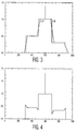
- an arbitrary simulated image scan line is shown in Fig. 3.
- the signal D is shown with a solid line.
- Its low-pass filtered version LP is shown superimposed with more slanting edges. It was derived by convolving the original waveform by a rectangular window of size 50.
- the processing consists of raising the signal curve D to an exponential power given by the filtered signal curve LP, all properly scaled, as described above.
- the size of the convoluting window for the low-pass filter is a parameter of the method. Typical values for a normal NTSC image sampled at 14.3 MHz rates, ranges from 20 to about 40.
- the video signal is convolved by a square window of uniform unit weight and size 31-by-31 for an NTSC video signal sampled at 14.3 MHz.
- Fig. 5 shows a block diagram of a television receiver.
- the television receiver includes an antenna input 10 for receiving television signals.
- the antenna input 10 is connected to a tuner circuit 20 for tuning to and receiving a particular television signal.
- An output from the tuner circuit 20 carrying a baseband composite video signal is applied to an input of a matrix circuit 30 for deriving the separate color signals R, G and B.
- These color signals are subjected to gamma correction as controlled by gamma correction circuit 40.
- the gamma corrected signals are then applied to a video signal processing circuit 50 for further processing and are then applied to a display 60 for displaying the resulting video images.
- Fig. 6 shows a block diagram of, in part, the gamma correction circuit 40 of Fig. 5.
- the R, G, B outputs from the matrix circuit 30 are applied to, on the one hand, the inputs of a variable gain amplifier arrangement 42, and, on the other hand, to a maximum determining circuit 44 for determining, pixel-by-pixel, the maximum of the three signals.
- An output V 1 of this maximum determining circuit 44 is subjected to analog-to-digital conversion in A/D 46 and is then applied to an input of digital signal processing (DSP) circuit 48.
- DSP digital signal processing
- This output is applied to a control input of the variable gain amplifier arrangement 42 for varying the gain thereof in accordance with the subject invention.
- the output from the variable gain amplifier arrangement 42 is then applied to the display 60 (via the video signal processing circuit 50).
- Fig. 7 shows an alternate embodiment to that shown in Fig. 6.
- each of the color signals is processed independently, Fig. 7 showing in detall the circuitry 40.1' for processing only one of the color signals, the other two color signals being processed similarly.
- the output from the matrix circuit 30 is applied to a low-pass filter 41.
- An output of the low-pass filter 41 is applied to a first normalization circuit 43 to which is applied the parameters A and B.
- This first normalization circuit 43 performs the calculation of Equation (4).
- the output from the matrix circuit 30 is also applied to a second normalization circuit 45.
- An output of the second normalization circuit 45 is applied to an exponential amplification circuit 47 which receives as its exponential input, the output from the first normalization circuit 43 and which performs the calculation of Equation (5).
- An output from the exponential amplification circuit 47 is then applied to a re-scaling circuit 49 for re-scaling the input signal thereto back to the full dynamic range of the input video signal.
- An output from this re-scaling circuit 49 is then applied to the display 60 via the video signal processing circuit 50.
- Equation (5) The use of the algorithm given in Equations (4) and (5) amplify low-level noise to an objectionable amount. This is due to the fact that the slope of Equation (5) is the gain at any given signal level. When g(x,y) approaches zero, the gain approaches infinity. The result is that the noise in the region of zero signal is amplified to a large extent.
- One approach is to modify Equation (5) so that it does not approach zero for small signals. Many arbitrary modifications could be used.
- the main requirement is that the slope of the system characteristic (Equation (5)) should not approach large values.
- Equation (10) the first two terms of a standard power-series expansion are taken. Theoretically, these first two terms are only sufficient to approximate the actual function in the limit as m ⁇ 1.
- Equation (11) the output of Equation (11) is g out (x,y) at these location.
- Fig. 8 shows a block diagram of a preferred embodiment of a digital implementation of the invention for use in a television receiver.
- R, G, B signals are derived from the source of composite video signals
- the R, G, B signals are digitized in analog-to-digital converters (A/D) 70, 72 and 74 forming the signals R in , G in , B in .
- A/D analog-to-digital converters
- these signals are converted to a single "luminance" like signal g(t) by replacing them by the maximum of R in , G in , B in at each location in maximum determining circuit 76.
- the resultant signal g(t) is stored in a frame store 78.
- the output from the frame store 78 is then normalized in a normalization circuit 80 giving the output signal g norm (x,y) which ranges from 0.0 to 1.0.
- the output from the normalization circuit 80 is applied to a convolver 82 which performs a two-dimensional averaging of g norm (x,y) and, after suitable rescaling as shown in Equation (9), outputs the signal h 1 (x,y).
- the level of this signal is shifted by subtracting 1.0 from it in the subtractor 84.
- the output from the subtractor 84 is multiplied by the input of convolver 82, g norm (x,y), in a multiplier 86.
- the level in this signal is then shifted by adding 1.0 to it in adder 88, the output therefrom being then applied to one input of a second multiplier 90.
- g norm (x,y) is applied as an address signal to a look-up table, which is in the form of a read-only memory 92. This look-up table performs the r function as defined in Equation (7), the output from which is applied to the other input of the second multiplier 90.
- the output from this second multiplier 90 g out (x,y) is then applied to the dividend input of divider 94 which receives the divisor input from the output of the normalization circuit 80.
- the output z(x,y) from the divider 94 is applied to the first inputs of respective multipliers 96, 98 and 100 which receive the signals R in , G in , B in from the outputs of the ADC's 70, 72 and 74, thereby forming the signals R out , G out , B out , respectively, as in Equations (13)-(15).
- Equation (11) The main difficulty with a direct implementation of Equation (11) is to find a method of producing, with real-time analog systems, g low (x,y), the two-dimensional low-pass filtered version of the input g in (x,y). This problem is solved in the following manner.
- g(t) be the one-dimensional, raster scanned representation of the two-dimensional scene g(x,y).
- the assumption is to generate the real-timed analog version of g(x,y) low-pass filtered by convolving with a uniform kernel of size 30 x 30.
- g(t) is band-limited to 4.3 MHz.
- g(t) is then passed through a conventional analog low-pass filter of bandwidth 4.3/30 MHz. If the normal sampling rate for the original video signal was 14.3 MHz, the output of the low-pass filtered signal can be adequately sampled at a 14.3/30 MHz rate. That would yield approximately 25 samples per horizontal video line.
- a kernel size of 30 vertical lines per frame equals 15 vertical lines per field.
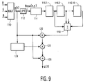
- Fig. 9 shows a preferred embodiment of an analog implementation of the invention also for use in a television receiver.
- the output from the sampling circuit 114 is applied to an analog delay line 116 having 15 stages (116.1-116.15), each stage 116.n including 25 single sample delay elements.
- the outputs from all of the stages 116.n are applied to a summing circuit 118 for implementing the two-dimensional averaging.
- This signal is applied to one input of a first multiplier 120 which receives at its other input g(t) at the output of the maximum determining circuit 110.
- the output of the first multiplier 120 is applied to a first input of a second multiplier 122.
- g(t) after being processed by a nonlinear circuit 124, is then applied to the second input of the second multiplier 122.
- the output from the second multiplier 122 is applied to the dividend input of divider 126 which receives g(t) at its divisor input.
- the output from the divider 126 is the function z(t) which is used to individually multiply the analog input functions R, G, B (not shown). It should be understood that this analog embodiment also requires DC shifts similar to those shown in Fig. 8 at adders 84 and 88.
Landscapes
- Engineering & Computer Science (AREA)
- Multimedia (AREA)
- Signal Processing (AREA)
- Picture Signal Circuits (AREA)
- Processing Of Color Television Signals (AREA)
Claims (10)
- Procédé pour procurer une commande dynamique du contraste par la correction de gamma d'un signal vidéo d'entrée dans un téléviseur comprenant les étapes :d'amener dans un filtre passe-bas le signal vidéo d'entrée, de telle sorte que le traitement porte seulement sur les composantes basse fréquence de celui-ci;de normaliser, pixel par pixel, le signal vidéo amené dans le filtre passe-bas de telle sorte que sa valeur s'étende de 0 jusqu'à une valeur maximale prédéterminée A, formant ainsi un signal normalisé;d'ajouter un paramètre prédéterminé B au signal normalisé, formant ainsi un exposant gamma;de normaliser le signal vidéo d'entrée de telle sorte que ses valeurs soient situées entre 0 et 1;d'élever, pixel par pixel, le signal vidéo normalisé à un exposant égal à l'exposant de gamma formant un signal vidéo normalisé corrigé; etde remise du signal vidéo normalisé corrigé à l'échelle de toute la gamme dynamique du signal vidéo d'entrée.
- Procédé pour procurer une commande dynamique du contraste par la correction de gamma d'un signal vidéo suivant la revendication 1, dans lequel A est choisi dans la gamme de 1,2 et 2,5.
- Procédé pour procurer une commande dynamique du contraste par la correction de gamma d'un signal vidéo suivant la revendication 2, dans lequel A est 1,34.
- Procédé pour procurer une commande dynamique du contraste par la correction de gamma d'un signal vidéo suivant la revendication 1, dans lequel B est choisi dans la gamme de valeurs entre 0,1 et 0,9.
- Procédé pour procurer une commande dynamique du contraste par la correction de gamma d'un signal vidéo suivant la revendication 4, dans lequel B est 0,45.
- Procédé pour procurer une commande dynamique du contraste par la correction de gamma d'un signal vidéo suivant la revendication 1, dans lequel ledit passage dans le filtre passe-bas du signal vidéo comprend la convolution du signal vidéo par une fenêtre carrée de poids et de taille unitaires uniformes 31 sur 31.
- Procédé pour procurer une commande dynamique du contraste par la correction de gamma d'un signal vidéo suivant la revendication 1, dans lequel ledit signal vidéo est un signal vidéo de couleur et ledit procédé est effectué sur chacune des composantes R, G et B du signal vidéo de couleur de manière individuelle.
- Circuit pour procurer une commande dynamique du contraste par la correction de gamma d'un signal vidéo dans un téléviseur, ledit circuit comprenant :une entrée pour recevoir un signal vidéo d'entrée;des moyens pour faire passer dans un filtre passe-bas ledit signal vidéo d'entrée;des moyens pour normaliser ledit signal vidéo amené dans un filtre passe-bas entre la gamme de 0,0 et une première quantité prédéterminée A, donnant un signal de sortie normalisé;des moyens pour additionner une deuxième quantité prédéterminée B audit signal de sortie normalisé, formant un signal exponentiel de gamma;des moyens couplés à ladite entrée pour normaliser ledit signal vidéo d'entrée entre la gamme de 0,0 et 1,0;des moyens pour augmenter ledit signal vidéo normalisé d'une quantité indiquée par ledit signal exponentiel de gamma, formant un signal vidéo normalisé corrigé; etdes moyens de remettre ledit signal vidéo normalisé corrigé à l'échelle de toute la gamme dynamique du signal vidéo d'entrée.
- Circuit numérique pour procurer une commande dynamique du contraste par la correction de gamma d'un signal vidéo dans un téléviseur, ledit circuit comprenant :des moyens d'entrée pour recevoir des signaux d'entrée R, G, B;des moyens pour numériser lesdits signaux d'entrée R, G, B, formant les signaux Rin, Gin, Bin;des moyens pour déterminer, pixel par pixel, un maximum desdits signaux Rin, Gin, Bin, formant ainsi un signal g(t);des moyens de mémorisation pour mettre en mémoire le signal g(t);des moyens couplés à une sortie desdits moyens de mémorisation pour normaliser g(t), formant un signal de sortie gnorm(x,y) dont la valeur se situe entre 0,0 et 1,0;des moyens de convolution pour effectuer une moyenne bi-dimensionnelle et pour remettre à l'échelle sur gnorm(x,y), donnant ainsi le signal h1(x,y) conformément à l'équationdes moyens de soustraction pour soustraire 1,0 de h1(x,y);un premier multiplicateur pour multiplier une sortie des moyens de soustraction par gnorm(x,y);des moyens d'addition pour additionner 1,0 à une sortie dudit premier multiplicateur;une table à consulter pour recevoir le signal gnorm(x,y) et pour mettre en oeuvre une fonction r conformément à l'équationun deuxième multiplicateur couplé à la sortie des moyens d'addition et de la table à consulter formant le signal gout(x,y);un diviseur couplé à une sortie du deuxième multiplicateur et à une sortie des moyens de normalisation pour former le facteur z(x,y) conformément à l'équationdes multiplicateurs couplés respectivement à des sorties desdits moyens de numérisation et chacun recevant la fonction z(x,y), formant ainsi les signaux de sortie Rout, Bout, Gout.
- Circuit analogique pour procurer un commande dynamique du contraste par la correction de gamma d'un signal vidéo dans un téléviseur, ledit circuit comprenant :une entrée pour recevoir des signaux d'entrée R, G, B;des moyens pour déterminer un maximum, pixel par pixel, des signaux d'entrée R, G, B, formant le signal g(t);des moyens pour amener dans un filtre passe-bas le signal g(t);des moyens pour échantillonner une sortie des moyens de passage dans un filtre passe-bas;des moyens de retard pour retarder une sortie desdits moyens d'échantillonnage, lesdits moyens de retard ayant une pluralité d'étages dont chacun a une sortie;des moyens pour sommer les sorties de ladite pluralité d'étages desdits moyens de retard;un premier multiplicateur ayant une première entrée couplée à la sortie desdits moyens de sommation et une deuxième entrée couplée à la sortie desdits moyens de détermination du maximum;un circuit non linéaire ayant une entrée couplée à la sortie desdits moyens de détermination du maximum;un deuxième multiplicateur ayant une première entrée couplée à une sortie dudit premier multiplicateur et une deuxième entrée couplée à une sortie dudit circuit non linéaire;un diviseur couplé à une sortie dudit deuxième multiplicateur et à la sortie desdits moyens de détermination du maximum pour former la fonction z(x,y); etdes moyens pour recevoir les signaux d'entrée R, G, B et pour multiplier ces signaux par la fonction z(x,y).
Applications Claiming Priority (2)
| Application Number | Priority Date | Filing Date | Title |
|---|---|---|---|
| US76565 | 1993-06-14 | ||
| US08/076,565 US5394195A (en) | 1993-06-14 | 1993-06-14 | Method and apparatus for performing dynamic gamma contrast control |
Publications (3)
| Publication Number | Publication Date |
|---|---|
| EP0630160A2 EP0630160A2 (fr) | 1994-12-21 |
| EP0630160A3 EP0630160A3 (fr) | 1997-01-02 |
| EP0630160B1 true EP0630160B1 (fr) | 2000-03-22 |
Family
ID=22132830
Family Applications (1)
| Application Number | Title | Priority Date | Filing Date |
|---|---|---|---|
| EP94201620A Expired - Lifetime EP0630160B1 (fr) | 1993-06-14 | 1994-06-07 | Contrôle dynamique du contraste par la correction de gamma |
Country Status (4)
| Country | Link |
|---|---|
| US (1) | US5394195A (fr) |
| EP (1) | EP0630160B1 (fr) |
| JP (1) | JPH07143358A (fr) |
| DE (1) | DE69423541T2 (fr) |
Families Citing this family (37)
| Publication number | Priority date | Publication date | Assignee | Title |
|---|---|---|---|---|
| JP3501252B2 (ja) * | 1995-06-16 | 2004-03-02 | 三菱電機株式会社 | 階調補正装置 |
| US5909249A (en) * | 1995-12-15 | 1999-06-01 | General Instrument Corporation | Reduction of noise visibility in a digital video system |
| EP0967809A1 (fr) * | 1998-06-22 | 1999-12-29 | Deutsche Thomson-Brandt Gmbh | Adaptation de gamma d'un processeur vidéo au moyen de trois courants de mesure |
| US6449389B1 (en) * | 1999-09-24 | 2002-09-10 | Xerox Corporation | Method and apparatus for single channel color image segmentation using local context based adaptive weighting |
| US6633343B2 (en) * | 2000-03-14 | 2003-10-14 | Matsushita Electric Industrial Co., Ltd. | Dynamic gamma correction apparatus |
| US7064740B2 (en) * | 2001-11-09 | 2006-06-20 | Sharp Laboratories Of America, Inc. | Backlit display with improved dynamic range |
| KR100590529B1 (ko) * | 2003-11-04 | 2006-06-15 | 삼성전자주식회사 | 영상의 국부적 휘도 향상 방법 및 장치와 컴퓨터프로그램을 저장하는 컴퓨터로 읽을 수 있는 기록 매체 |
| WO2005052673A2 (fr) | 2003-11-21 | 2005-06-09 | Sharp Laboratories Of America, Inc. | Affichage a cristaux liquides a couleurs adaptatives |
| US7164284B2 (en) * | 2003-12-18 | 2007-01-16 | Sharp Laboratories Of America, Inc. | Dynamic gamma for a liquid crystal display |
| JP4497959B2 (ja) | 2004-03-05 | 2010-07-07 | キヤノン株式会社 | 映像信号処理装置及び映像信号処理方法 |
| US7602369B2 (en) * | 2004-05-04 | 2009-10-13 | Sharp Laboratories Of America, Inc. | Liquid crystal display with colored backlight |
| US20050248553A1 (en) * | 2004-05-04 | 2005-11-10 | Sharp Laboratories Of America, Inc. | Adaptive flicker and motion blur control |
| US7532192B2 (en) * | 2004-05-04 | 2009-05-12 | Sharp Laboratories Of America, Inc. | Liquid crystal display with filtered black point |
| US7612757B2 (en) * | 2004-05-04 | 2009-11-03 | Sharp Laboratories Of America, Inc. | Liquid crystal display with modulated black point |
| US8395577B2 (en) * | 2004-05-04 | 2013-03-12 | Sharp Laboratories Of America, Inc. | Liquid crystal display with illumination control |
| US7505018B2 (en) * | 2004-05-04 | 2009-03-17 | Sharp Laboratories Of America, Inc. | Liquid crystal display with reduced black level insertion |
| US7872631B2 (en) * | 2004-05-04 | 2011-01-18 | Sharp Laboratories Of America, Inc. | Liquid crystal display with temporal black point |
| US7777714B2 (en) * | 2004-05-04 | 2010-08-17 | Sharp Laboratories Of America, Inc. | Liquid crystal display with adaptive width |
| US7023451B2 (en) * | 2004-06-14 | 2006-04-04 | Sharp Laboratories Of America, Inc. | System for reducing crosstalk |
| US7556836B2 (en) * | 2004-09-03 | 2009-07-07 | Solae, Llc | High protein snack product |
| US7898519B2 (en) * | 2005-02-17 | 2011-03-01 | Sharp Laboratories Of America, Inc. | Method for overdriving a backlit display |
| TWI326443B (en) * | 2004-10-27 | 2010-06-21 | Chunghwa Picture Tubes Ltd | Dynamic gamma correction circuit, method thereof and plane display device |
| US8050512B2 (en) | 2004-11-16 | 2011-11-01 | Sharp Laboratories Of America, Inc. | High dynamic range images from low dynamic range images |
| US7525528B2 (en) * | 2004-11-16 | 2009-04-28 | Sharp Laboratories Of America, Inc. | Technique that preserves specular highlights |
| US8050511B2 (en) * | 2004-11-16 | 2011-11-01 | Sharp Laboratories Of America, Inc. | High dynamic range images from low dynamic range images |
| US9143657B2 (en) * | 2006-01-24 | 2015-09-22 | Sharp Laboratories Of America, Inc. | Color enhancement technique using skin color detection |
| US8121401B2 (en) * | 2006-01-24 | 2012-02-21 | Sharp Labortories of America, Inc. | Method for reducing enhancement of artifacts and noise in image color enhancement |
| KR100809347B1 (ko) | 2006-07-31 | 2008-03-05 | 삼성전자주식회사 | 쉐도우 영역 보상 방법 및 장치 |
| US8941580B2 (en) * | 2006-11-30 | 2015-01-27 | Sharp Laboratories Of America, Inc. | Liquid crystal display with area adaptive backlight |
| KR100866486B1 (ko) | 2007-01-04 | 2008-11-03 | 삼성전자주식회사 | 주변광 적응적인 색 보정 장치 및 방법 |
| JP5241031B2 (ja) * | 2009-12-08 | 2013-07-17 | ルネサスエレクトロニクス株式会社 | 表示装置、表示パネルドライバ、及び画像データ処理装置 |
| DE102011055269A1 (de) * | 2011-11-11 | 2013-05-16 | Jenoptik Robot Gmbh | Verfahren zur Durchführung einer Dynamikkompression in der Verkehrsfotografie |
| US9324137B2 (en) * | 2012-10-24 | 2016-04-26 | Marvell World Trade Ltd. | Low-frequency compression of high dynamic range images |
| JP5574015B2 (ja) * | 2013-05-27 | 2014-08-20 | 株式会社ニコン | 画像処理装置、電子カメラおよび画像処理プログラム |
| CN107209927B (zh) * | 2014-09-19 | 2020-07-03 | 巴尔科股份有限公司 | 利用减少的视觉假象提高对比度的方法 |
| CN113900147B (zh) * | 2020-07-06 | 2024-05-28 | 中国石油天然气股份有限公司 | 沙丘鸣震压制方法及系统 |
| CN112532958B (zh) * | 2020-11-24 | 2022-09-06 | 海宁奕斯伟集成电路设计有限公司 | 图像处理方法、装置、电子设备以及可读存储介质 |
Family Cites Families (5)
| Publication number | Priority date | Publication date | Assignee | Title |
|---|---|---|---|---|
| DE2921246A1 (de) * | 1979-05-25 | 1980-12-04 | Bosch Gmbh Robert | Verfahren und schaltung zur kontrastkorrektur von farbfernsehsignalen |
| JPS56107674A (en) * | 1980-01-31 | 1981-08-26 | Sony Corp | Gradation correcting device of video signal |
| US4667228A (en) * | 1983-10-14 | 1987-05-19 | Canon Kabushiki Kaisha | Image signal processing apparatus |
| ATE83110T1 (de) * | 1987-02-11 | 1992-12-15 | Digivision Inc | Im echtzeitbetrieb arbeitende lokale videobildverbesserung mit trennbaren zweidimensionalen filtern. |
| US4829381A (en) * | 1988-04-18 | 1989-05-09 | Polaroid Corporation | System and method for electronic image enhancement by dynamic pixel transformation |
-
1993
- 1993-06-14 US US08/076,565 patent/US5394195A/en not_active Expired - Fee Related
-
1994
- 1994-06-07 EP EP94201620A patent/EP0630160B1/fr not_active Expired - Lifetime
- 1994-06-07 DE DE69423541T patent/DE69423541T2/de not_active Expired - Fee Related
- 1994-06-14 JP JP6132059A patent/JPH07143358A/ja active Pending
Also Published As
| Publication number | Publication date |
|---|---|
| EP0630160A3 (fr) | 1997-01-02 |
| US5394195A (en) | 1995-02-28 |
| JPH07143358A (ja) | 1995-06-02 |
| EP0630160A2 (fr) | 1994-12-21 |
| DE69423541T2 (de) | 2000-09-21 |
| DE69423541D1 (de) | 2000-04-27 |
Similar Documents
| Publication | Publication Date | Title |
|---|---|---|
| EP0630160B1 (fr) | Contrôle dynamique du contraste par la correction de gamma | |
| US6724943B2 (en) | Device and method for image processing | |
| US5237402A (en) | Digital image processing circuitry | |
| US7551794B2 (en) | Method apparatus, and recording medium for smoothing luminance of an image | |
| JP3828251B2 (ja) | 映像のダイナミックレンジ拡大装置 | |
| JP5003196B2 (ja) | 画像処理装置および方法、並びに、プログラム | |
| RU2146425C1 (ru) | Способ и схемы избирательного повышения четкости (варианты) | |
| JP2001275015A (ja) | 画像処理回路及び画像処理方法 | |
| US6915023B2 (en) | Contour correction device | |
| JP2007049540A (ja) | 画像処理装置および方法、記録媒体、並びに、プログラム | |
| JP2001298621A (ja) | 画像処理装置及びその方法 | |
| JP3293951B2 (ja) | デジタルガンマ補正器において利得を制限するための装置及び方法 | |
| KR101311817B1 (ko) | 이미지 디테일 향상 | |
| JP3184309B2 (ja) | 階調補正回路及び撮像装置 | |
| US20090002562A1 (en) | Image Processing Device, Image Processing Method, Program for Image Processing Method, and Recording Medium Having Program for Image Processing Method Recorded Thereon | |
| KR20010075557A (ko) | 비디오 신호 향상 방법 및 장치 | |
| US7561189B2 (en) | Method and apparatus of image dynamic response re-mapping and digital camera using the same | |
| JP2003348377A (ja) | 画像表示装置および画像処理装置、並びに画像処理方法 | |
| JP4174656B2 (ja) | 画像表示装置および画像処理装置、並びに画像処理方法 | |
| JP2008072450A (ja) | 画像処理装置及び画像処理方法 | |
| JPH0646293A (ja) | 輪郭補正装置 | |
| JP2935389B2 (ja) | 映像信号処理装置及び非線形信号処理装置 | |
| JPH09224186A (ja) | ビデオカメラおよび輪郭補正装置 | |
| JPH11284880A (ja) | 撮像装置 | |
| KR0185930B1 (ko) | 신호레벨에 따라 임계레벨을 설정하는 영상신호의 노이즈 제거장치 |
Legal Events
| Date | Code | Title | Description |
|---|---|---|---|
| PUAI | Public reference made under article 153(3) epc to a published international application that has entered the european phase |
Free format text: ORIGINAL CODE: 0009012 |
|
| AK | Designated contracting states |
Kind code of ref document: A2 Designated state(s): DE FR GB |
|
| PUAL | Search report despatched |
Free format text: ORIGINAL CODE: 0009013 |
|
| AK | Designated contracting states |
Kind code of ref document: A3 Designated state(s): DE FR GB |
|
| 17P | Request for examination filed |
Effective date: 19970702 |
|
| GRAG | Despatch of communication of intention to grant |
Free format text: ORIGINAL CODE: EPIDOS AGRA |
|
| 17Q | First examination report despatched |
Effective date: 19990517 |
|
| GRAG | Despatch of communication of intention to grant |
Free format text: ORIGINAL CODE: EPIDOS AGRA |
|
| GRAG | Despatch of communication of intention to grant |
Free format text: ORIGINAL CODE: EPIDOS AGRA |
|
| GRAH | Despatch of communication of intention to grant a patent |
Free format text: ORIGINAL CODE: EPIDOS IGRA |
|
| GRAH | Despatch of communication of intention to grant a patent |
Free format text: ORIGINAL CODE: EPIDOS IGRA |
|
| GRAA | (expected) grant |
Free format text: ORIGINAL CODE: 0009210 |
|
| AK | Designated contracting states |
Kind code of ref document: B1 Designated state(s): DE FR GB |
|
| PG25 | Lapsed in a contracting state [announced via postgrant information from national office to epo] |
Ref country code: FR Free format text: THE PATENT HAS BEEN ANNULLED BY A DECISION OF A NATIONAL AUTHORITY Effective date: 20000322 |
|
| REF | Corresponds to: |
Ref document number: 69423541 Country of ref document: DE Date of ref document: 20000427 |
|
| PG25 | Lapsed in a contracting state [announced via postgrant information from national office to epo] |
Ref country code: GB Free format text: LAPSE BECAUSE OF NON-PAYMENT OF DUE FEES Effective date: 20000622 |
|
| ET | Fr: translation filed | ||
| PLBE | No opposition filed within time limit |
Free format text: ORIGINAL CODE: 0009261 |
|
| STAA | Information on the status of an ep patent application or granted ep patent |
Free format text: STATUS: NO OPPOSITION FILED WITHIN TIME LIMIT |
|
| GBPC | Gb: european patent ceased through non-payment of renewal fee |
Effective date: 20000622 |
|
| 26N | No opposition filed | ||
| PG25 | Lapsed in a contracting state [announced via postgrant information from national office to epo] |
Ref country code: DE Free format text: LAPSE BECAUSE OF NON-PAYMENT OF DUE FEES Effective date: 20010403 |