EP0630436B1 - Bouclier porte-lames pour le creusement de tranchees ouvertes dans le sol - Google Patents
Bouclier porte-lames pour le creusement de tranchees ouvertes dans le sol Download PDFInfo
- Publication number
- EP0630436B1 EP0630436B1 EP93906542A EP93906542A EP0630436B1 EP 0630436 B1 EP0630436 B1 EP 0630436B1 EP 93906542 A EP93906542 A EP 93906542A EP 93906542 A EP93906542 A EP 93906542A EP 0630436 B1 EP0630436 B1 EP 0630436B1
- Authority
- EP
- European Patent Office
- Prior art keywords
- blade
- trench
- knives
- knife
- blades
- Prior art date
- Legal status (The legal status is an assumption and is not a legal conclusion. Google has not performed a legal analysis and makes no representation as to the accuracy of the status listed.)
- Expired - Lifetime
Links
Images


Classifications
-
- E—FIXED CONSTRUCTIONS
- E21—EARTH OR ROCK DRILLING; MINING
- E21D—SHAFTS; TUNNELS; GALLERIES; LARGE UNDERGROUND CHAMBERS
- E21D9/00—Tunnels or galleries, with or without linings; Methods or apparatus for making thereof; Layout of tunnels or galleries
- E21D9/06—Making by using a driving shield, i.e. advanced by pushing means bearing against the already placed lining
- E21D9/0692—Cutter drive shields
-
- E—FIXED CONSTRUCTIONS
- E02—HYDRAULIC ENGINEERING; FOUNDATIONS; SOIL SHIFTING
- E02D—FOUNDATIONS; EXCAVATIONS; EMBANKMENTS; UNDERGROUND OR UNDERWATER STRUCTURES
- E02D17/00—Excavations; Bordering of excavations; Making embankments
- E02D17/06—Foundation trenches ditches or narrow shafts
- E02D17/08—Bordering or stiffening the sides of ditches trenches or narrow shafts for foundations
- E02D17/086—Travelling trench shores
-
- E—FIXED CONSTRUCTIONS
- E02—HYDRAULIC ENGINEERING; FOUNDATIONS; SOIL SHIFTING
- E02F—DREDGING; SOIL-SHIFTING
- E02F5/00—Dredgers or soil-shifting machines for special purposes
- E02F5/02—Dredgers or soil-shifting machines for special purposes for digging trenches or ditches
- E02F5/10—Dredgers or soil-shifting machines for special purposes for digging trenches or ditches with arrangements for reinforcing trenches or ditches; with arrangements for making or assembling conduits or for laying conduits or cables
- E02F5/101—Dredgers or soil-shifting machines for special purposes for digging trenches or ditches with arrangements for reinforcing trenches or ditches; with arrangements for making or assembling conduits or for laying conduits or cables forming during digging, e.g. underground canalisations or conduits, by bending or twisting a strip of pliable material; by extrusion
Definitions
- the invention relates to a knife shield with horizontal and vertical control for the continuous driving of open trenches in the ground.
- the shoring cage consists of two formwork walls, divided in the longitudinal plane, on the two lateral ends of the shoring cage.
- the formwork walls are connected to one another via guides, double-acting hydraulic cylinders being arranged between the formwork walls.
- the well-known sheeting cage does not allow continuous driving and can only be used for trenches with the same dimensions. It is not possible to reuse the sheeting basket for trenches with other depths. In such a case, a new sheeting cage must be used. Further disadvantages of the known construction basket are that neither horizontal nor vertical control of the shoring basket is possible.
- the desired continuous propulsion is possible in that the individual pairs of knives are pressed forward one after the other by a fixed distance and at the same time the excavation is carried out before the head of the trench.
- the individual knives can be individually driven independently of one another. When the knife shield is driven straight ahead, the two knives forming the pair of knives are driven simultaneously and by the same distance. On the other hand, when cornering (horizontal control), which is also possible with the proposed knife shield, the knives forming the pair of knives are driven one after the other, but at least by different lengths.
- the support devices consist of hydraulically operated presses that can be retracted if necessary to facilitate the advance of the knives resting on the presses.
- the proposed knife shield is particularly suitable for laying pipelines by using individual pipe pieces in its rear region, ie in the region of the knife tails, with the end region of the knife tails again thereafter is filled with soil and compacted.
- a compressor can advantageously be arranged at the end of the knife shield and can thus be carried continuously in the direction of advance.
- the respective support devices are relaxed or lifted off the trench bottom in order to facilitate the advancement of the corresponding pair of knives.
- the weight of the entire knife shield is then removed from the supports of the other pair of knives which are at a standstill.
- the knives arranged on the trench side walls are preferably designed in one piece and are identical.
- the individual knives are divided into three areas, namely the so-called knife head, the knife tail and the knife body in between. However, it is also possible to assemble individual areas of each knife from individual pieces, for example to screw them together.
- each pair of knives are connected to one another via two cross supports.
- a pair of knives connected by two cross supports is called a shoring element.
- each framework or shoring element represents a horizontally arranged frame.
- the entire knife shield consists of several frames or shoring elements arranged one above the other, depending on the corresponding trench depth. If the knife shield is to be reused for a trench with different trench heights, only additional frameworks need to be arranged or omitted in a simple manner.
- the first cross support is preferably arranged in the area between the cutter head and the cutter body and the second cross support in the area between the cutter body and the cutter tail.
- the area between the cutter heads which is arranged in front of the front cross supports as seen in the direction of advance, is used for excavation.
- the cross supports are preferably detachably connected to the knives, for example to facilitate their interchangeability and above all to allow space-saving folding when transporting the entire knife shield.
- the connection of the cross supports to the knife can preferably be done using screws.
- the transverse supports are expediently designed to be adjustable in length with respect to their longitudinal axis, in order to enable easy adaptation to a new width of the trench when the knife shield is reused for other trenches.
- the length can be adjusted, for example, via integrated spindles or extendable supports or similar devices.
- the cross supports can be easily replaced due to the detachable connection with the knives.
- Spacers are advantageously arranged between the knives arranged one above the other, which are connected to the underside of the upper knives facing the bottom of the trench and only rest on the top of the adjacent lower knives facing away from the bottom of the trench.
- the spacing devices expediently consist of webs or pins or similar suitable devices.
- Two pins are preferably provided per knife, the number of which can be increased as desired, depending on the length of the knife used in each case.
- two pins are arranged, they are preferably arranged on the one hand in the area between the cutter head and the cutter body and on the other hand in the area between the cutter body and the cutter tail.
- the length of the pin is dimensioned such that the knives lying one above the other are spaced apart. The friction between the neighboring knives is thus avoided when the individual knives are being driven. Friction between the knives only arises from the support of the spacing devices on the respective neighboring knives, wherein measures to reduce friction, such as, for example, appropriately designed surfaces or the use of low-friction materials or coatings can be provided in a simple manner.
- guide devices can be formed on the upper side of the knives facing away from the trench bottom, which cooperate with the spacing devices in such a way that the knives lying on a trench wall, one above the other, run essentially in a common vertical plane during the advance. Since the proposed knife shield is preferably used for trenches whose side walls run in the vertical direction, a common vertical alignment of all the knives of a side wall is sought, which can be achieved with the proposed guide device.
- the individual knives are preferably designed, in particular the knife body lying between the knife head and the knife tail, as a double-T support, one flange surface of which faces the trench side wall.
- This cross-sectional configuration chosen for the knives enables, on the one hand, a lightweight construction of the knives with the required section modulus and, on the other hand, the formation of suitable guide devices.
- the guide devices expediently consist of at least one wedge surface which is formed between the web of the double-T support and a flange half and which continuously reduces the distance between the opposite flange surfaces, as viewed in the opposite direction to the direction of advance. If necessary, several such guide devices can be formed on the respective knives. When a wedge surface is formed, it is preferably arranged in the front area of the knives.
- the guide device in the form of wedge surfaces interacts with the spacing device, for example in the form of the pins or webs. As the knives having the spacer device advance, they are forced into the desired position by the wedge surfaces in the maximum advance position.
- each knife has either the guiding or spacing device on the opposite outer surfaces of the webs, so the guiding and spacing device is not arranged on the same side of the webs of the knife designed as a double-T beam.
- the forced alignment of the individual knives results in the ultimately desired, essentially vertical course of the knives lying one above the other on a trench side wall when all knives are driven.
- overlapping covers are preferably arranged on the surfaces of the knives facing the trench side wall. These covers are about the Whole or at least over a substantial part of the entire length of the respective knives is provided in order to prevent the soil from collapsing out of the trench side walls into the exposed trench, in particular when the knives lying one above the other are arranged at a distance from one another.
- the feed presses can in particular be operated hydraulically.
- the feed presses can be operated individually, in particular independently of one another, in the pushing and / or pulling direction, so that any knife can be driven individually or in pairs.
- the advance of the individual knives can be achieved either by retracting or extending the corresponding feed presses, it being understood that a further feed press arranged on the knife to be driven can either support the advance, but at least be pulled together or moved apart in order to advance of the corresponding knife.
- the feed presses are advantageously arranged on the superimposed knives in the area between the knife head and the knife body of one knife and in the area between the knife body and the knife tail of the other knife, preferably between the front and rear cross supports.
- the knives of the last two pairs of knives which are arranged one above the other and which are closest to the bottom of the trench are advantageously connected to one another via two feed presses in order to facilitate the advance of the respective knives. This is particularly advantageous if a clearing blade is arranged in the area of these two pairs of knives, which clears the trench bottom, as a result of which the forces to be overcome when driving the knives increase.
- two presses are expediently arranged in the region between the measuring head and the knife body and two presses in the region between the knife body and the knife tail.
- a symmetrical arrangement of the presses to one another is also advantageous.
- the presses of the last pair of knives closest to the bottom of the trench are advantageous in the area of the knives, i.e. in the vicinity of the respective trench side walls.
- the presses of the penultimate pair of knives closest to the trench sole are arranged on the cross supports, preferably in the region of the connection of the cross support to the knives, or via angle pieces on the knives of the penultimate framework arranged to occupy the desired location next to the knives of the lowest framework.
- the presses of the last and the penultimate pair of knives arranged in the front area are extended or lowered differently with respect to the correspondingly arranged presses in the rear area. retracted. The upward or downward movement can thus be carried out in a simple manner.
- the presses lying one behind the other in the direction of advance are preferably supported on a runner, the underside of which rests on the bottom of the trench.
- the soil pressure can be reduced by the increased contact area, so that an excessively deep sinking of the support devices below the trench bottom level can be avoided.
- a clearing blade is advantageously arranged in the front area of the penultimate pair of knives closest to the trench bottom, the lower edge of which rests on the trench bottom.
- the clearing blade serves to level the trench bottom when the corresponding frame element is advanced.
- the level control of the dozer blade can be carried out using a laser and a target plate.
- the clearing blade is expediently designed to be height-adjustable in order to be able to be adapted to a changing trench bottom level.
- a trencher can be expediently arranged in the front area of the knife shield.
- the arrangement of a trencher is particularly expedient because the proposed blade shield eliminates downtimes and enables the blade shield to be driven continuously. It is advantageous if the movement of the knives is automated by the feed presses with a hydraulic sequential circuit. If no cornering is desired, the two knives of each framework are simultaneously advanced from above to the bottom of the trench by the same distance, so that the individual frameworks are continuously moved forward in succession.
- the surface of the knife facing the trench side wall is bent in the end region of the knife head towards the middle of the trench and a sliding part is arranged on the surface which runs obliquely towards the trench side wall and forms the tip of the knife head.
- the free end of the sliding part forms the tip of the cutter head. If the tip of the knife head lies on the same level as the area of the knife behind the retraction, this framework is caused to drive straight ahead when a pair of knives are being driven. If, on the other hand, the free end of the sliding part is moved away towards the center of the trench, this knife moves laterally towards the center of the trench. It goes without saying that in the opposite knife of the same framework, the free end of the sliding part is displaced in the opposite direction beyond the total level of the area of the knife behind the retraction to the trench side wall in order to support the desired horizontal movement of the corresponding framework.
- the free end of the sliding part advantageously has teeth in order to facilitate the advance of the respective knife.
- the adjustment or displacement of the sliding part is preferably made possible by a controllable adjusting device arranged between the knife and the sliding part, the respective adjusting devices of the individual knives being operable and dependent on one another.
- lowering devices are arranged on the undersides of the knives of the last pair of knives closest to the bottom of the trench, which facilitate the sinking of the knife shield in the event that instead of a separate construction pit, which is produced with the required dimensions before the knife shield is inserted, to work with the lowering process.
- the lowering device preferably consists of cutting edges.
- the cross section of the cutting edges preferably has essentially the shape of a right-angled triangle, a tip of this triangle being directed towards the bottom of the trench in order to support the penetration of the entire knife blade as the excavation progresses into the excavation pit.
- the tip of this triangle forms the cutting edge, which can in particular be provided with individual, spaced-apart cutting teeth.
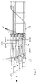
- FIGS. 1 to 10 schematically show a preferred embodiment of the knife shield according to the invention along with some variants.
- the basic structure of the knife shield is first explained with reference to FIGS. 1 to 3, which show a cross section in the longitudinal and transverse directions and a plan view of the knife shield, the arrow A indicating the direction of advance.
- sections of trenches can be exposed, in particular for laying pipes, in-situ concrete channels or lines.
- a trench section with trench side walls 2 which extend essentially in the vertical direction and a trench bottom 4 which extends essentially horizontally.
- Knives 6 lying opposite one another are referred to as pairs of knives 6.
- transverse supports 8 are arranged in the space between them, which are arranged on the sides of the knives 6 pointing towards the center of the trench.
- the cross supports 8 are firmly connected to the knives 6, for example by screws, but this connection can be released.
- For each pair of knives 6 are advantageously spaced apart, preferably in the front or rear Area of the knives 6 arranged cross supports 8 are provided.
- a pair of knives 6 together with the cross supports 8 connected to them is referred to as a framework or shoring element.
- the knives 6 consist of three areas, namely the knife head 10, the knife tail 12 and the knife body 14 lying in between.
- the knives 6 can be formed in one piece or in sections from individual parts.
- the knives 6 of each framework, one on top of the other are formed at a distance from one another.
- the individual knives 6 of the knife shield are basically of the same design. However, their length is different, with opposing knives 6 of a shoring element also being the same in terms of their length.
- the lowermost knives 6 of the lowest framework, which are closest to the trench bottom 4, are the shortest, while the knives 6 above are each designed a little longer.
- the end of all the knives 6 is arranged in a common, essentially vertically extending plane, which also applies to the transverse support 8 arranged in the rear region of the knife shield. Stair-shaped arrangements in the rear area are also possible.
- the different lengths of the knives 6 lying one above the other result in an oblique course at the front end of the knife shield, which essentially corresponds to the angle of repose which arises in the excavation area.
- the free ends of the knives 6, seen from the side are inclined, the free ends of all cutter heads 10 lie essentially in one plane. Stepping is also possible here.
- the front cross supports 8 are arranged correspondingly offset.
- the area resulting between the free end of the cutter heads 10 and the respective cross supports 8 represents a cantilever arm, wherein due to the offset arrangement of the cross supports 8, the cantilever arms of all knives 6 are of approximately the same length.
- the cross supports 8 are designed to be variable in length with respect to their longitudinal axis. If a substantially wider or narrower trench is to be created the next time it is reused, the cross supports 8 can be replaced in a simple manner on account of their detachable connection with the knives 6.
- the individual knives 6 or frameworks are guided in the vertical direction by spacing devices in the form of pins 28 arranged on the underside of the knives 6 facing the trench bottom 4.
- the pins 28 are fixedly arranged on the underside of the knives 6 and are supported on the ones below , the upper side of the underlying knife 6, which is closer to the grave sole 4, is therefore not firmly connected to it.
- the knives 6 are preferably identical and, at least in the area of the knife body 14, are designed as double-T supports, a flange surface facing the respective grave side wall 2, the flanges thus extending in cross section essentially in the vertical direction, whereas that between the flanges located Web, seen in cross section, extends substantially in the horizontal direction.
- covers 18 are provided on the flange surfaces facing the trench side walls 2, which can also overlap one another.
- the covers 18 can consist of metal plates that are thin in cross-section and preferably extend over the entire length, but at least over the length of the knife body 10 and part of the adjoining knife tail 12.
- the knives 6 lying one above the other are each connected to one another via at least one feed press 20 (FIG. 1).
- a feed press 20 between the superimposed knives 6 is sufficient since, however, a clearing plate 22 is arranged on the penultimate framework, as seen in the direction of the pit floor 4, two feed presses 20 are arranged on each of the respective knives 6 of the penultimate framework in order to to be able to more easily overcome the additional friction forces caused by the clearing plate 22 which levels the pit base 4.
- the knife shield is supported on the trench bottom 4 by means of support devices in the form of, in particular, hydraulically actuated supporting presses or presses 24.
- the last two pairs of knives 6 facing the trench bottom 4 each have four such presses 24.
- the presses 24 are arranged in the last pair of knives 6 closest to the trench bottom in the area of the knives 6, so that each of these knives 6 is supported by two presses 24.
- the presses 24 are arranged on the cross supports 8, preferably in the region of the connection of the cross support 8 to the knives 6.
- the presses 24 are for the better Distribution of the pressure not directly on the trench bottom 4, but on runners 26, each pair of presses 24 lying one behind the other, viewed in the direction of advance, standing on a respective runners 26.
- the length of the runner 26 results from the spacing of the presses 24 arranged one behind the other plus a protrusion in the direction of advance and against the direction of advance.
- the clearing blade 22 is arranged, which is preferably designed to be height-adjustable.
- the five feed presses 20 shown in FIG. 1 are additionally designated with the letters A to E. It goes without saying that these feed presses 20 are also arranged in the opposite knives 6 in the same way as is indicated in FIG. 2.
- the knife shield is being driven, the uppermost pair of knives 6, the so-called uppermost framework, which is the most distant from the bottom 4 of the trench, is started.
- the opposing feed presses 20 of each framework are extended or retracted simultaneously and by the same length.
- the uppermost framework is driven by means of the presses 20A, the piston rods of which are attached to the uppermost framework and the cylinder tubes of which are attached to the underlying framework, by extending the piston rods.
- the propulsion of the framework located below the uppermost framework and the middle framework takes place analogously to the propulsion of the uppermost framework, whereby the upper feed presses 20, which are in the extended state, are inoperative or can be retracted under pressure and are thus pushed in again when the framework below is being propelled or moved in.
- the upper feed presses 20 which are in the extended state, are inoperative or can be retracted under pressure and are thus pushed in again when the framework below is being propelled or moved in.
- the penultimate framework closest to the trench bottom 4 Before the penultimate framework closest to the trench bottom 4 is driven, its runners 26 are lifted off the trench bottom 4 or at least by one by retracting or relieving the corresponding presses 24 Part of the dead weight of the knife shield is relieved. The entire dead weight of the knife shield is then removed by the presses 24 or runners 26 of the last framework closest to the trench bottom 4.
- the piston rod of the feed presses 20D is on the penultimate framework, the cylinder tube of which is attached to the last framework.
- the feed press 20E is in the extended state, the cylinder of which is attached to the penultimate framework and the piston rod of which is attached to the last framework.
- the piston rods of the feed presses 20D extend, the piston rods of the feed presses 20E being retracted at the same time. After the propulsion of the penultimate framework, the presses 24 and the associated runners 26 are extended again.
- the skids 26 are first retracted or relieved, as in the penultimate framework, by actuating the corresponding presses 24.
- the feed presses 20E are extended, the piston rods of the feed presses 20D being simultaneously retracted to support the advance.
- its presses 24 are extended again together with the runners 26 in order to also remove part of the dead weight of the knife shield.
- a new tunneling game then begins, starting with the top framework.
- the control of the knife shields in the vertical direction takes place during lifting by extending the front ones, seen in the direction of advance Presses 24 of the penultimate and last framework. This will raise the entire knife shield at the front.
- the upward movement of the knife shield can be supported by simultaneously retracting or relaxing the rear presses 24 of the penultimate and last framework. If, on the other hand, the knife shield is to be steered downward, ie in the direction of the trench bottom 4, the front presses 24 of the penultimate and last framework are relaxed or somewhat lowered. Under the influence of its own weight, the entire knife shield then moves downward during further advance.
- the downward movement of the knife shield can in turn be supported in that the rear presses 24 of the penultimate and last framework are extended or extended under increased pressure.
- the horizontal control of the knife shield i.e. propulsion deviating from the straight-ahead drive to the right or left, that is to say when cornering, can be achieved by an uneven propulsion of the knives 6 of each individual framework, starting with the uppermost framework facing away from the trench bottom 4.
- only the corresponding feed presses 20 have to be extended to different extents, so that the corresponding framework experiences a directional deviation. Should e.g. If a right turn is made, the feed press 20 on the left in the direction of advance is extended correspondingly more than the right feed press 20 on the opposite side.
- the horizontal control movement is supported by a corresponding design of the cutter heads 10, as will be explained later with reference to FIG. 8.
- the advance of the individual frameworks with the help of the feed press 20 can be automated with a hydraulic sequential circuit, so that a continuous advance of the entire knife blade is made possible. Since downtimes are thus eliminated when the blade shield is being driven, the front blade of the proposed blade shield can be used In the area for excavating the trench, a continuously working ridge cutter can be used instead of excavating with a separate device, for example an excavator arranged in front of the trench.
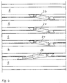
- FIG. 4 shows a variant in the arrangement of the feed presses 20, the knives 6 of each frame lying one above the other being connected to one another in each case by a feed press 20.
- the feed press 20 connecting the penultimate and the last framework must be operable in both directions, i.e., extendable with pressure and retractable accordingly. If one assumes 20 100% for the compressive force of a feed press, its tensile force is only about 50% of its compressive force because of the smaller ring area compared to its piston surface. In the arrangement shown in FIG.
- the lowermost feed press 20 must be retracted in order to advance the knife 6 or framework which is penultimate in relation to the trench bottom 4, so that subsequently only 50% of the compressive force is available for this, unless that the overlying feed press 20 is also drawn in.
- this reduced compressive force may not be sufficient for propulsion, since in addition to the penultimate framework, the clearing blade 22 must also be driven forward. It may therefore be necessary, for example, as shown in FIGS. 1 to 3, to arrange an arrangement of two feed presses 20, namely the feed presses 20D and 20E, between the penultimate and last framework, which are then moved together by pushing or pulling. Drive in the penultimate framework.
- Fig. 5 shows a further variant of the arrangement of feed presses 20 in a likewise of five frameworks existing knife shield.
- the top two and the bottom two frameworks or knives 6 are connected to one another via two feed presses 20, one feed press 20 being in the retracted state and the other feed press 20 being in the extended state.
- the other frameworks or knives 6 are connected to one another via a feed press 20.
- each framework can be driven with a propulsive force of 150% of the compressive force of each feed press 20.
- the feed presses 20 shown in FIG. 5 are arranged in an identical manner on the opposite knives 6 on the opposite, not shown, side of the knife shield. 5, 20 (100%) can then be exerted with one feed press while 20 (50%) can be exerted with the corresponding other feed press.
- FIG. 6 and 7 show the arrangement of spacing and guiding devices between knives 6 arranged one above the other.
- FIG. 6 shows a cross section in the transverse direction through two knives 6 arranged one above the other, while FIG. 7 shows a section along line II from FIG 6 represents.
- the spacing device is designed in the form of the pin 28.
- the pin 28 is fixedly arranged on the underside of the upper knife 6, for example welded on, while it merely rests on the upper side of the lower knife 6.
- the length of the pin 28 is dimensioned such that the desired distance between the knives 6 results, in particular taking into account the maximum permitted distance between the covers 18 placed on the knives 6 on the trench side wall 2, not shown, which here do not overlap, for example are formed, but have a small distance or gap from one another, the size of which is such that as little earth as possible can fall from the trench side walls between the covers 18 into the interior of the knife shield.
- two such pins 28 are preferably arranged.
- the free end of the pin 28 can be coated, for example, with a particularly low-friction material.
- guide devices in the form of wedges 30 are arranged which cooperate with the pins 28.
- the knives 6 are designed in cross section as double T-beams, so that the pins 28 are arranged on the opposite web surfaces of the respective knives 6.
- the wedges 30 are formed on the upper side of the knives 6 between the web of the double-T support and a flange half and, viewed against the direction of advance (arrow A), continuously reduce the distance between the opposite flange surfaces.
- the wedges 30 run over at their free end into an area which no longer continuously reduces the distance between the flanges but constricts uniformly over a certain distance. In this area the pin 28 of the knife 6 lying above it will be arranged when it is in front of the next advance.
- the driving of the uppermost framework is first started, the knives 6 of which are driven, for example, to different extents.
- the horizontal movement of the uppermost framework or its knife 6, ie the deviation to the right or left, is not hindered by the formation of the wedge surfaces or the wedges 30, since these, seen in the direction of advance, taper and thus the distance between widen the opposite flanges.
- each pin 28 there is a wedge 30, the height of which preferably corresponds to half the height of the flange of the knife 6.
- the pins 28 support the individual frameworks with one another, so that ultimately the dead weight of the knife shield can be introduced into the runners 26 via the pins 28.
- the relative movement of the individual frameworks in the horizontal direction possible by the propulsion is thus limited by the interaction between the wedges 30 or their wedge surfaces and the pin 28 to such an extent that the individual frameworks are approximately perpendicular to one another after the propulsion cycle has ended.
- FIG. 8 shows a top view of the end region of a knife 6 or its knife head 10.
- the knife shield according to the invention preferably has knives 6, the knife heads 10 of which are designed in an identical manner according to FIG. 8.
- the tip of the cutter head 10 is not only reached by a beveling of the end area of the surface pointing towards the center of the cutter shield. Rather, the cutter head 10 initially has a sliding part in its end region 32, the free end of which forms the tip of the cutter head 10.
- the longitudinal axis of the displacement part 32 points obliquely to the trench side wall 2, not shown, and is in particular essentially parallel to the oblique design of the surface of the end region of the cutter head 10 pointing towards the center of the trench.
- the sliding part 32 is guided in the end region of the cutter head 10 and can be moved via an adjusting device 34 arranged on the free end of the sliding part 32 facing away from the trench side wall 2.
- the adjustment device 34 can, for example, from a spindle or the like. exist, the displacement of the sliding part 32 is preferably automatically controllable.
- the free end of the sliding part 32 facing the trench side wall 2 preferably has teeth in order to facilitate the advancement of the corresponding knife 6.
- the surface of the knife 6 facing the trench side wall 2 is bent in the end region of the knife head 10 towards the middle of the trench, as a result of which a type of indentation 36 is formed.
- the free end of the retraction merges into the sliding part 32 and is in particular spaced accordingly from the trench side wall 2.
- the displacement part 32 supports the horizontal control of the knife shield, which, however, can in principle take place via a different propulsion of the knives 6 of each framework. If the knife 6 according to FIG. 8 is intended to support a movement of the corresponding framework to the right, ie downwards in FIG. 8, the displacement part 32 is pushed back by the adjusting device 34, ie it is moved away from the trench side wall 2 towards the center of the trench. The recess 36 formed on the outside of the knife 6 deflects the knife head 10 and thus the entire knife 6 in the desired direction. If, on the other hand, the knife is to be controlled in the opposite direction, ie the corresponding framework to the left or upwards with respect to FIG.
- the sliding part 32 is pushed outwards, ie towards the side wall 2 of the trench, so that the tip of the sliding part 32 is over the recess 36 adjoining surface of the knife 6 protrudes into the trench side wall 2 or protrudes.
- the tip of the sliding part 32 thus cuts a corresponding over-profile into which the cutter head 10 can move in order to condition or support the desired change in direction.
- the sliding part 32 is bent in its end region towards the direction of advance, so that a certain area of the free area of the sliding part 32 bears against the trench side wall 2. This surface is designed to support the most precise possible straight-ahead travel when advancing the knife shield, parallel to the surface of the knives 6 adjoining the indentation 36 and abutting the trench side wall 2.
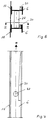
- FIG. 9 finally shows a lowering device for the lowering process of the knife shield at the start of its installation in a trench to be created in the form of a cross section in the transverse direction through the penultimate and last framework of the knife shield according to the invention.
- the formation of the free end of the lowering device facing the trench bottom 4 is shown in FIG. 10.
- a lowering device is arranged if no own construction pit with the required dimensions has been created beforehand, in which the individual frameworks can then be assembled. In this case, the so-called lowering process is used.
- some frameworks, consisting of the knives 6 and the cross supports 8 connecting them, are placed one on top of the other, the lowest framework - as shown in FIG. 9 - being provided with longitudinal cutting edges 38.
- the cutting edges 38 preferably extend over the entire length of the two knives 6 of the lowermost framework, but at least over a substantial part of their entire length.
- the cutting edges 38 are each detachably arranged on the undersides of the two knives 6 of the last framework.
- Its cross section is preferably in the form of a right-angled triangle, wherein a tip of this triangle is pointing towards the not shown grave base 4.
- the right angle between the trench side wall 2, not shown, and the underside of the corresponding knife 6 will be arranged.
- the downward-pointing angle of the triangular cross section of the cutting edges 38 represents the cutting edge, which can be straight or, as shown in FIG. 10, can also be tooth-shaped, that is to say it has free-standing teeth 40 spaced apart from one another.
- the knife shield lowers as the excavation progresses into the excavation pit. This lowering movement can be supported by a reciprocating movement of the corresponding feed cylinders 20 between the penultimate and last framework. As soon as the desired position of the knife shield is reached, the cutting edges 38 are loosened and removed from the excavation pit, the presses 24 then being installed together with the runners 26 on the undersides of the knives 6 of the last framework facing the trench sole 4. The corresponding presses 24 and runners 26 of the penultimate framework can then be arranged on its cross supports 8.
Landscapes
- Engineering & Computer Science (AREA)
- Mining & Mineral Resources (AREA)
- Structural Engineering (AREA)
- Civil Engineering (AREA)
- General Engineering & Computer Science (AREA)
- Life Sciences & Earth Sciences (AREA)
- Mechanical Engineering (AREA)
- General Life Sciences & Earth Sciences (AREA)
- Paleontology (AREA)
- Environmental & Geological Engineering (AREA)
- Geochemistry & Mineralogy (AREA)
- Geology (AREA)
- Excavating Of Shafts Or Tunnels (AREA)
- Sewage (AREA)
Abstract
Claims (9)
- Bouclier à lames à commande horizontale et verticale pour le creusement en continu de tranchées ouvertes dans le sol, qui comporte des éléments de blindage soutenant les parois latérales (2) de la tranchée, disposés les uns au-dessus des autres et coulissants longitudinalement les uns par rapport aux autres dans la direction d'avance, ces éléments de blindage comportant chacun une paire de lames (6) disposées à l'opposé l'une de l'autre, pour la mise en place et l'appui des parois latérales (2) de la tranchée, et deux poutres d'appui transversal (8), par l'intermédiaire desquels les lames (6) de la paire de lames (6) sont reliées l'une à l'autre pour réaliser un bâti de cadre, les lames (6) disposées les unes au-dessus des autres de deux éléments de blindage disposés contigus l'un au-dessus de l'autre étant reliées chaque fois l'une à l'autre par l'intermédiaire d'au moins un vérin d'avance par poussage (20) et les emplacements de liaison de chaque vérin d'avance par poussage (20) avec la lame supérieure correspondante (6), étant disposés décalés horizontalement par rapport à l'emplacement de liaison avec la lame inférieure (6) correspondante, caractérisé en ce que sont prévus au moins trois éléments de blindage, dont les deux derniers sont appuyés, par l'intermédiaire d'organes d'appui, sur le fond de tranchée (4) de la plus proche paire de lames (6), ces organes d'appui, se composant chacun de quatre vérins de levage (24) susceptibles d'être actionnés hydrauliquement.
- Bouclier à lames selon la revendication 1, dans lequel le premier appui transversal (8) est disposé dans la zone entre la tête de lame (10) et le corps de lame (14) de la lame (6), tandis que la deuxième poutre d'appui transversal (8) est disposé dans la zone entre le corps de lame (14) et la queue de lame (12) de la lame (6).
- Bouclier à lames selon la revendication 1 ou 2, dans lequel les poutres d'appui transversal (8) sont réalisées réglables en longueur selon leurs axes longitudinaux.
- Bouclier à lames selon l'une des revendications 1 à 3, dans lequel, entre les lames (6) disposés l'une au-dessus de l'autre, sont disposés des organes d'écartement, qui sont disposés isolément en étant reliés à la face inférieure, tournés vers le fond de tranchée (4), de chaque lame supérieure correspondante (6), et à la face supérieure, tournée à l'opposé du fond de tranchée (4), de la lame inférieure correspondante, voisine (6).
- Bouclier à lames selon l'une des revendications 1 à 4, dans lequel sont prévus, sur chaque face supérieure des lames (6) tournée à l'opposé du fond de tranchée (4), des organes de guidage, qui coopèrent avec les organes de guidage de telle façon que les lames (6) disposées sur une paroi latérale (2) de la tranchée soient orientées sensiblement dans un même plan vertical commun.
- Bouclier à lames selon l'une des revendications 1 à 5, dans lequel les vérins d'avance par poussage (20) sont disposés sur les lames (6) se recouvrant mutuellement, dans la zone entre la tête de lame (10) et le corps de lame (14) de l'une des lames (6) et dans la zone entre le corps de lame (14) et la queue de lame (12) de l'autre des lames (6), en particulier dans la zone entre les poutres d'appui transversal (8).
- Bouclier à lames selon l'une des revendications 1 à 6, dans lequel les lames (6) disposées les unes au-dessus des autres des deux dernières paires de lames (6) les plus proches du fond de la tranchée (4) sont reliées l'une à l'autre par l'intermédiaire de deux vérins d'avance par poussage (20).
- Bouclier à lames selon l'une des revendications 1 à 7, dans lequel, pour les dernières paires de lames (6) les plus proches du fond (4) de la tranchée, sont disposés deux vérins de levage (24), chacun dans la zone entre la tête de lame (10) et le corps de lame (14), et deux vérins de levage (24) dans la zone entre le corps de lame (14) et la queue de lame (12).
- Bouclier à lames selon l'une des revendications 1 à 8, dans lequel la surface de la lame tournée vers la paroi latérale (2) de la tranchée est réalisée, dans la zone d'extrémité de la tête de lame (10), cambrée vers le milieu de la tranchée, et en ce que, sur la surface formant la pointe de la tête de lame (10) et s'éloignant en biais de la paroi latérale (2) de la tranchée et en face de cette paroi, est disposée une pièce coulissante (32) dont l'extrémité libre forme la pointe de la tête de lame (10).
Applications Claiming Priority (3)
| Application Number | Priority Date | Filing Date | Title |
|---|---|---|---|
| DE19924208972 DE4208972C1 (de) | 1992-03-19 | 1992-03-19 | Messerschild zum Vortrieb von offenen Gräben im Boden |
| DE4208972 | 1992-03-19 | ||
| PCT/EP1993/000645 WO1993019253A1 (fr) | 1992-03-19 | 1993-03-18 | Bouclier porte-lames pour le creusement de tranchees ouvertes dans le sol |
Publications (2)
| Publication Number | Publication Date |
|---|---|
| EP0630436A1 EP0630436A1 (fr) | 1994-12-28 |
| EP0630436B1 true EP0630436B1 (fr) | 1997-08-27 |
Family
ID=6454538
Family Applications (1)
| Application Number | Title | Priority Date | Filing Date |
|---|---|---|---|
| EP93906542A Expired - Lifetime EP0630436B1 (fr) | 1992-03-19 | 1993-03-18 | Bouclier porte-lames pour le creusement de tranchees ouvertes dans le sol |
Country Status (4)
| Country | Link |
|---|---|
| EP (1) | EP0630436B1 (fr) |
| DE (1) | DE4208972C1 (fr) |
| ES (1) | ES2108268T3 (fr) |
| WO (1) | WO1993019253A1 (fr) |
Families Citing this family (6)
| Publication number | Priority date | Publication date | Assignee | Title |
|---|---|---|---|---|
| DE9308555U1 (de) * | 1993-06-08 | 1993-09-16 | Matthäi-Bauunternehmen GmbH & Co. Betriebs-KG, 27283 Verden | Vorrichtung zum Austausch von Bodenmaterial, insbesondere neben Verkehrswegen und Bauwerken |
| EP0667419A1 (fr) * | 1994-02-09 | 1995-08-16 | Heinz Brecht | Dispositif de blindage de tranchée |
| FR2722220B1 (fr) * | 1994-07-08 | 1996-08-23 | Gec Alsthom T & D Sa | Dispositif de soutenement d'une tranchee creussee en continu |
| DE19737003A1 (de) * | 1997-08-26 | 1999-03-04 | Weiss Gmbh & Co Leonhard | Selbsttätig fortschreitende Grabenaushubeinrichtung mit Messerschilden |
| KR20040079350A (ko) * | 2004-07-28 | 2004-09-14 | 주식회사 한유건설 | 건설 구조물용 스크류잭 |
| DE102024127407A1 (de) | 2024-09-23 | 2026-03-26 | Tim Skupin | Verbauplatte und Verfahren zum Verschließen einer Verbaulücke |
Family Cites Families (7)
| Publication number | Priority date | Publication date | Assignee | Title |
|---|---|---|---|---|
| DE577108C (de) * | 1933-05-23 | Bauschaefer Akt Ges Fuer Bergm | Aus einzelnen Vortriebsmessern bestehender Vortriebsschild fuer den Tunnel- oder Stollenvortrieb | |
| DE2135577C3 (de) * | 1971-07-16 | 1975-01-30 | Heinz 7526 Rheinsheim Brecht | Verbaukorb zum kontinuierlich fortschreitenden Verbau eines Kanalgrabens |
| DE2523340C3 (de) * | 1975-05-27 | 1981-01-08 | Gewerkschaft Eisenhuette Westfalia, 4670 Luenen | Vorrichtung zum Verlegen eines Rohrstranges in einem Graben |
| DE2706243A1 (de) * | 1977-02-15 | 1978-08-17 | Gewerk Eisenhuette Westfalia | Messerschild, insbesondere fuer den offenen grabenverbau |
| DE3134071A1 (de) * | 1981-08-28 | 1983-03-10 | Gewerkschaft Eisenhütte Westfalia, 4670 Lünen | Gleitender messerverbau fuer den grabenvortrieb zur durchfuehrung von rohrverlegearbeiten im erdreich |
| DE3363513D1 (en) * | 1982-09-17 | 1986-06-19 | Heinz Brecht | Shoring apparatus for the shoring of trenches |
| DE3443282A1 (de) * | 1984-11-28 | 1986-05-28 | Gewerkschaft Eisenhütte Westfalia, 4670 Lünen | Gleitender messerverbau fuer den leitungsgrabenbau |
-
1992
- 1992-03-19 DE DE19924208972 patent/DE4208972C1/de not_active Expired - Fee Related
-
1993
- 1993-03-18 EP EP93906542A patent/EP0630436B1/fr not_active Expired - Lifetime
- 1993-03-18 WO PCT/EP1993/000645 patent/WO1993019253A1/fr not_active Ceased
- 1993-03-18 ES ES93906542T patent/ES2108268T3/es not_active Expired - Lifetime
Also Published As
| Publication number | Publication date |
|---|---|
| DE4208972C1 (de) | 1993-12-02 |
| EP0630436A1 (fr) | 1994-12-28 |
| WO1993019253A1 (fr) | 1993-09-30 |
| ES2108268T3 (es) | 1997-12-16 |
Similar Documents
| Publication | Publication Date | Title |
|---|---|---|
| EP2010717A2 (fr) | Procédé et dispositif servant au blindage de tranchées | |
| EP0630436B1 (fr) | Bouclier porte-lames pour le creusement de tranchees ouvertes dans le sol | |
| CH632307A5 (de) | Baugrubenverbau fuer einen graben oder ein loch. | |
| DE3141763C2 (de) | Teilschnittschrämmaschine | |
| DE4230533C2 (de) | Vorrichtung zum Austausch von Bodenmaterial, insbesondere neben Verkehrswegen und Bauwerken | |
| DE2742332C3 (de) | Lenkbare Messerschildvortriebseinrichtung und Vortriebsmesser | |
| EP0476037B1 (fr) | Dispositif d'ouverture et de soutenement de galeries d'avancement | |
| DE3729561C2 (fr) | ||
| DE3443282A1 (de) | Gleitender messerverbau fuer den leitungsgrabenbau | |
| DE1942759C3 (de) | Vorrichtung für das Auffahren eines Tunnels im Messervortriebsverfahren | |
| DE2406215A1 (de) | Vorrichtung und verfahren zum verlegen grossvolumiger rohre, insbesondere pipelines | |
| EP0258699B1 (fr) | Bouclier à couteaux et méthode pour l'avencement et/ou soutènement de tunnels etc. | |
| DE3134071A1 (de) | Gleitender messerverbau fuer den grabenvortrieb zur durchfuehrung von rohrverlegearbeiten im erdreich | |
| DE2622201C2 (de) | Messerschild | |
| DE2622202C2 (de) | Verfahren und Einrichtung zum Auffahren eines tiefen Grabens im Messerschildverfahren, insbesondere für die Errichtung von Tunnelbauwerken | |
| DE2161392C2 (de) | Verfahren und Vorrichtung zum Herstellen von Tunneln in offener Baugrube | |
| DE976347C (de) | Strebausbau mit Rueckmaschine | |
| DE4419694C2 (de) | Vorrichtung zum Austausch von Bodenmaterial | |
| DE4211383C2 (de) | Abspannbock für den Untertagebetrieb mit seitlicher Verspannung an gegenüberliegenden Stößen | |
| DE2530127C3 (de) | Verbauschild für den Vortrieb von Tunneln, Stollen u.dgl | |
| DE69308114T2 (de) | Verfahren zur Herstellung von Querdurchgängen unter Eisenbahntrassen | |
| DE10207126A1 (de) | Grabenfräse | |
| DE6603768U (de) | Vortriebsschild fuer den ausbau offener baugruben | |
| DE3629729C2 (fr) | ||
| DE2625446C2 (de) | Vorrichtung und Verfahren zum Verbauen von Gräben |
Legal Events
| Date | Code | Title | Description |
|---|---|---|---|
| PUAI | Public reference made under article 153(3) epc to a published international application that has entered the european phase |
Free format text: ORIGINAL CODE: 0009012 |
|
| 17P | Request for examination filed |
Effective date: 19940928 |
|
| AK | Designated contracting states |
Kind code of ref document: A1 Designated state(s): CH ES FR GB IT LI PT |
|
| 17Q | First examination report despatched |
Effective date: 19960125 |
|
| GRAG | Despatch of communication of intention to grant |
Free format text: ORIGINAL CODE: EPIDOS AGRA |
|
| GRAH | Despatch of communication of intention to grant a patent |
Free format text: ORIGINAL CODE: EPIDOS IGRA |
|
| GRAH | Despatch of communication of intention to grant a patent |
Free format text: ORIGINAL CODE: EPIDOS IGRA |
|
| GRAA | (expected) grant |
Free format text: ORIGINAL CODE: 0009210 |
|
| AK | Designated contracting states |
Kind code of ref document: B1 Designated state(s): CH ES FR GB IT LI PT |
|
| PG25 | Lapsed in a contracting state [announced via postgrant information from national office to epo] |
Ref country code: IT Free format text: LAPSE BECAUSE OF FAILURE TO SUBMIT A TRANSLATION OF THE DESCRIPTION OR TO PAY THE FEE WITHIN THE PRE;WARNING: LAPSES OF ITALIAN PATENTS WITH EFFECTIVE DATE BEFORE 2007 MAY HAVE OCCURRED AT ANY TIME BEFORE 2007. THE CORRECT EFFECTIVE DATE MAY BE DIFFERENT FROM THE ONE RECORDED.SCRIBED TIME-LIMIT Effective date: 19970827 Ref country code: GB Free format text: LAPSE BECAUSE OF FAILURE TO SUBMIT A TRANSLATION OF THE DESCRIPTION OR TO PAY THE FEE WITHIN THE PRESCRIBED TIME-LIMIT Effective date: 19970827 |
|
| REG | Reference to a national code |
Ref country code: CH Ref legal event code: EP |
|
| ET | Fr: translation filed | ||
| REG | Reference to a national code |
Ref country code: CH Ref legal event code: NV Representative=s name: PATENTANWAELTE SCHAAD, BALASS, MENZL & PARTNER AG |
|
| REG | Reference to a national code |
Ref country code: ES Ref legal event code: FG2A Ref document number: 2108268 Country of ref document: ES Kind code of ref document: T3 |
|
| REG | Reference to a national code |
Ref country code: PT Ref legal event code: SC4A Free format text: AVAILABILITY OF NATIONAL TRANSLATION Effective date: 19971021 |
|
| GBV | Gb: ep patent (uk) treated as always having been void in accordance with gb section 77(7)/1977 [no translation filed] |
Effective date: 19970827 |
|
| PLBE | No opposition filed within time limit |
Free format text: ORIGINAL CODE: 0009261 |
|
| STAA | Information on the status of an ep patent application or granted ep patent |
Free format text: STATUS: NO OPPOSITION FILED WITHIN TIME LIMIT |
|
| 26N | No opposition filed | ||
| REG | Reference to a national code |
Ref country code: FR Ref legal event code: D6 |
|
| PGFP | Annual fee paid to national office [announced via postgrant information from national office to epo] |
Ref country code: FR Payment date: 20010110 Year of fee payment: 9 |
|
| PGFP | Annual fee paid to national office [announced via postgrant information from national office to epo] |
Ref country code: PT Payment date: 20010115 Year of fee payment: 9 |
|
| PGFP | Annual fee paid to national office [announced via postgrant information from national office to epo] |
Ref country code: CH Payment date: 20020925 Year of fee payment: 10 |
|
| PG25 | Lapsed in a contracting state [announced via postgrant information from national office to epo] |
Ref country code: PT Free format text: LAPSE BECAUSE OF NON-PAYMENT OF DUE FEES Effective date: 20020930 |
|
| PG25 | Lapsed in a contracting state [announced via postgrant information from national office to epo] |
Ref country code: FR Free format text: LAPSE BECAUSE OF NON-PAYMENT OF DUE FEES Effective date: 20021129 |
|
| REG | Reference to a national code |
Ref country code: PT Ref legal event code: MM4A Free format text: LAPSE DUE TO NON-PAYMENT OF FEES Effective date: 20020930 |
|
| REG | Reference to a national code |
Ref country code: FR Ref legal event code: ST |
|
| PGFP | Annual fee paid to national office [announced via postgrant information from national office to epo] |
Ref country code: ES Payment date: 20030328 Year of fee payment: 11 |
|
| PG25 | Lapsed in a contracting state [announced via postgrant information from national office to epo] |
Ref country code: LI Free format text: LAPSE BECAUSE OF NON-PAYMENT OF DUE FEES Effective date: 20030331 Ref country code: CH Free format text: LAPSE BECAUSE OF NON-PAYMENT OF DUE FEES Effective date: 20030331 |
|
| REG | Reference to a national code |
Ref country code: CH Ref legal event code: PL |
|
| PG25 | Lapsed in a contracting state [announced via postgrant information from national office to epo] |
Ref country code: ES Free format text: LAPSE BECAUSE OF NON-PAYMENT OF DUE FEES Effective date: 20040320 |
|
| REG | Reference to a national code |
Ref country code: ES Ref legal event code: FD2A Effective date: 20040320 |