EP0630493B1 - Verfahren und vorrichtung zur automatischen modifikation eines graphisches displays basierend auf einer steuerprogrammodifikation - Google Patents
Verfahren und vorrichtung zur automatischen modifikation eines graphisches displays basierend auf einer steuerprogrammodifikation Download PDFInfo
- Publication number
- EP0630493B1 EP0630493B1 EP93907286A EP93907286A EP0630493B1 EP 0630493 B1 EP0630493 B1 EP 0630493B1 EP 93907286 A EP93907286 A EP 93907286A EP 93907286 A EP93907286 A EP 93907286A EP 0630493 B1 EP0630493 B1 EP 0630493B1
- Authority
- EP
- European Patent Office
- Prior art keywords
- station
- work station
- diagnostic work
- program
- control program
- Prior art date
- Legal status (The legal status is an assumption and is not a legal conclusion. Google has not performed a legal analysis and makes no representation as to the accuracy of the status listed.)
- Expired - Lifetime
Links
Images




Classifications
-
- G—PHYSICS
- G05—CONTROLLING; REGULATING
- G05B—CONTROL OR REGULATING SYSTEMS IN GENERAL; FUNCTIONAL ELEMENTS OF SUCH SYSTEMS; MONITORING OR TESTING ARRANGEMENTS FOR SUCH SYSTEMS OR ELEMENTS
- G05B19/00—Program-control systems
- G05B19/02—Program-control systems electric
- G05B19/04—Program control other than numerical control, i.e. in sequence controllers or logic controllers
- G05B19/05—Programmable logic controllers, e.g. simulating logic interconnections of signals according to ladder diagrams or function charts
- G05B19/058—Safety, monitoring
Definitions
- This invention relates to methods and systems that monitor the operation of manufacturing devices and, particularly, to a method and system for automatically modifying the graphic display of a diagnostic work station upon detecting a change to the logic of the programmable control station being monitored.
- the operation of the programmable control station, and its coupled automated machinery is monitored through the use of a diagnostic work station coupled to the programmable control station.
- the diagnostic work station is programmed to display information concerning the status and operation of the coupled programmable control station and associated automated machinery.
- the display of the diagnostic work station informs operating personnel of fault conditions, device states, signal levels, switch settings and other information useful in diagnosing malfunctions and maintaining appropriate controls on the automated machinery.
- information regarding the operation of the programmable control station and the automated machinery is presented to the operator of the diagnostic work station through a graphic display representing the logic of the programmable control station and/or the relationships between various elements of the monitored system.
- FIGURE 1 is a flow chart illustrating a first prior art approach to this situation describing a method of manually modifying the program controlling the diagnostic work station to reflect the modified control logic of the programmable control station.
- the program controlling the diagnostic work station periodically updates the graphic display of the diagnostic work station to reflect the status of the attached programmable control station and automated machinery.
- an operator of the diagnostic work station visually checks the diagnostic work station's graphic display to detect the possibility of an error in the process performed by the programmable control station and the automated machinery. If no error is detected, no action is taken by the operator of the diagnostic work station and the process continues. If, however, the operator of the diagnostic work station detects an error, the operator must investigate whether the error is caused by an equipment failure or a modification of the control logic of the programmable control station.
- the operator of the diagnostic work station To determine the source of the error, the operator of the diagnostic work station, through inquiries made on the plant floor, must determine whether the control logic of the programmable control station has been modified. If the control logic of the programmable control station has been modified, the process must be shut down. If the control logic of the programmable control station has not been modified, the logic of the current program of the diagnostic work station must be compared to the logic of the prior program of the diagnostic work station, as indicated by a program listing kept on file.
- the logic of the program controlling the diagnostic work station If the logic of the program controlling the diagnostic work station has been modified, it must be reviewed, analyzed and reprogrammed to accurately reflect the control logic of the programmable control station. If the logic of the program controlling the diagnostic work station has not been modified, either the responses to inquiries made on the plant floor were erroneous or there is an equipment failure. In either event, the process must be shut down.
- a listing of the current program of the programmable control station must be compared to a listing of the prior program of the programmable control station as indicated by a program listing kept on file. If it is determined that the programmable control station logic has not been modified, the operator of the diagnostic work station can reasonably assume that an equipment failure has caused the error. If it is determined that the logic of the programmable control station has been modified, the current logic of the programmable control station must be reviewed and the program of the diagnostic work station must be altered to reflect those changes in the control logic of the programmable control station in order to accurately monitor the programmable control station. After the diagnostic work station has been reprogrammed, the process may be restarted.
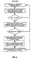
- FIGURE 2 is a flowchart illustrating the second prior art approach to this situation, describing the method disclosed by U.S.P.N. 4,670,834 of Byal et al.
- Byal et al. discloses a system and method for automatic diagnostic program modification based on control program modification.
- the program controlling the diagnostic work station periodically updates the graphic display of the diagnostic work station to reflect the status of the attached programmable control station and automated machinery.
- the diagnostic work station is attached to a central management information system which is used to detect whether the programmable control station is in run mode. If the programmable control station is in run mode, no action is taken and the process continues. If, however, the programmable control station is not in run mode, the central management information system uploads the current program controlling the programmable control station and compares this current program with a copy of the prior program controlling the programmable control station. The prior program controlling the programmable control station is retained on file by the central management information system.
- the central management information system determines that the current program controlling the programmable control station is the same as the prior program controlling the programmable control station, no action is taken and the process continues. If, however, the current program controlling the programmable control station is different than the prior program controlling the programmable control station, the central management information system automatically analyzes the logic of the current program controlling the programmable control station.
- the central management information system then creates a new program to control the diagnostic work station based on the current program controlling the programmable control station. Finally, the central management information system downloads the new monitor program to the diagnostic work station, and the process is restarted.
- FIGURE 1 The manual approach illustrated by FIGURE 1 is particularly time-consuming and expensive. This method requires a number of individuals having highly specialized skills to work together to achieve an adequate solution to the problem. The high level of human intervention renders this solution inefficient and undesirable.
- FIGURE 2 also lacks efficiency and economy.
- This method requires additional equipment, namely a central management information system, to process and analyze the changes in the control program of the programmable control station.
- a new monitor program for the diagnostic work station must be created and downloaded to the diagnostic work station.
- the present invention described and disclosed herein comprises a method and system of automatically modifying the graphic display of a diagnostic work station upon detecting a change in the control program of a coupled programmable control station.
- An object of the present invention is to provide a method and system for automatically modifying the graphic display of a diagnostic work station upon detecting a change in the control program of a coupled programmable control station wherein the change in the control program of the programmable control station does not necessitate updating the monitor program of the diagnostic work station.
- Another object of the present invention is to provide a method and system for automatically modifying the graphic display of a diagnostic work station upon detecting a change in the control program of a coupled programmable control station wherein the method and system will operate within the diagnostic work station, eliminating the need for additional equipment.
- a method is provided as claimed in claim 1.
- Said method is for automatically modifying the graphic display of a diagnostic work station upon detecting a change in the control program of a coupled programmable control station.
- the method includes the step of ascertaining whether the programmable control station is in run mode.
- the method also comprises the step of comparing the current control program with the prior control program upon detecting that the programmable control station is not in run mode.
- the method additionally includes the step of analyzing the current control logic to determine the contents of a new graphics display representing the current control logic.
- the method further includes the step of utilizing the monitor program to cause the diagnostic work station to display the new graphics display.
- the diagnostic work station using the monitor program, displays a modified graphics display representative of the current control logic of the current control program.
- One important feature of the present invention is the ability to couple more than one programmable control station to a single diagnostic work station.
- the monitor program permits a user of the diagnostic work station to select which coupled programmable control station will be monitored and represented via the graphic display by the monitor program.
- Another important feature of the present invention is the ability of the monitor program to update a graphic display representing the control logic of the programmable control station and the attached machinery at any time.
- a user may wish to update the graphic display upon starting a process regardless of whether a change to the control program has actually occurred. This simply configures the graphic display to correctly monitor the newly started process without requiring the creation of a monitor program from scratch.
- a final important feature of the present invention is the ability of the monitor program to prompt a user of the diagnostic work station upon detecting that a possible control program change has occurred. This allows the user to decide whether he or she wishes to cause the monitor program to update the graphic display. If the user of the diagnostic workstation knows that the control program has not been substantively changed, the user has the option of not causing the monitor program to update the graphic display.
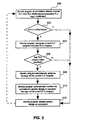
- FIGURE 3 illustrates the method of the present invention.
- the monitor program at the diagnostic work station detects whether the programmable control station is in run-mode. If the programmable control station is in run-mode, the monitor program passes control from block 302 to block 312 and continues normal operations by updating the graphic display of the work station to indicate the status of the automated machinery.
- the monitor program must compare the current control program of the programmable control station with a file copy of the prior control program of the programmable control station as described by block 304. As shown by block 306, if the monitor program determines that no modification of the control program has occurred, the monitor program continues normal operations as described by block 312.
- block 308 is performed and the monitor program automatically analyzes the logic of the current control program of the programmable control station. As described by block 310, the monitor program automatically modifies the graphic display of the diagnostic work station to represent the logic of the current control program of the programmable control station. Finally, the monitor program performs the step of block 312 and resumes normal operations by updating the graphic display of the work station to indicate the status of the automated machinery.
- FIGURE 4 illustrates the hardware needed to monitor and perform typical automated manufacturing operations.
- FIGURE 4 illustrates the hardware needed to monitor and perform typical automated manufacturing operations.
- an IBM or compatible personal computer 10 operating as a diagnostic work station and having a monitor program 12 is connected via a communications link 14 to a programmable logic controller 16.
- the programmable logic controller 16 operating as a programmable control station and having a control program 18, is connected via a communications link 20 to automated machinery 22.
- the automated machinery 22 can take many forms and perform many functions.
- the automated machinery 22 takes the form of a tank-fill system which has been implemented in a plant and that the personal computer 10 is used to monitor the status of the pump in this system.
- FIGURE 5 illustrates the individual components of the automated machinery for this specific example.
- the pump 20 is used to pump fluid 22 into a tank 24.
- the pump 20 is connected to the programmable logic controller 16 via an output line 26.
- the pump 20 is also connected to the programmable logic controller 16 via first input 28.
- the programmable logic controller 16 receives an input from a full switch 30 via an input 32.
- Output 26, input 28 and input 32 communicate the state of a device as either "on” or "off”.
- an operator will turn “on” a pump switch 38 which, in turn, turns “on” the pump 20.
- the pump 20 will be turned “off”.
- control program 18 has a very simple function. As long as the state of input 28 is "on”, the control program 18 continuously tests the state of the full switch 30. Once the control program 18 determines that the state of the full switch 30 is "on”, indicating the tank 24 is full of fluid 22, the control program 18 directs the programmable logic controller 16 to change the state of output 26 from “on” to "off” causing the pump 20 to stop filling the tank 24.
- the monitor program 12 graphically displays on the personal computer 10 a representation of the various components of the automated machinery 22, their relationship to one another and their state (i.e. "on” or “off”).
- the monitor program 12 allows the operator of the personal computer 10 to verify the correct operation of the automated machinery 22. For instance, if the graphic display shows that the full switch 30 is "on” and the pump 20 has not gone “off", the operator of the personal computer must take action to determine and correct the source of the problem. In this case, it is possible that either the full switch 30 or the pump 20 has failed.
- FIGURE 6 illustrates the same configuration of machinery as FIGURE 5 with the addition of a float switch 34 which is connected to the programmable logic controller 16 via input 36.
- the float switch 34 determines a low level of fluid 22 in the tank 24.
- the control program 18 is altered to set the state of output 26 to "on", when input 28 is “off", but input 36 is "on”. This addition functions to turn the pump "on” when the fluid 22 reaches a sufficiently low level so as to turn float switch 34 on.
- the process In order to appropriately alter the control program 18, the process must be temporarily suspended by taking the programmable logic controller 16 out of run mode.
- the operator of the personal computer 10 is informed that there may be changes to the control program 18 of the programmable logic controller 16.
- the operator of the personal computer 10 instructs the monitor program 12 to analyze the current logic of the control program 18.
- the monitor program 12 then causes the personal computer 10 to display an updated graphic representation of the process, including the recently added float switch 34. This graphic display is updated automatically, requiring no research of the process logic of the control program 18 and no research into the wiring of either the programmable logical controller 16 or the automated machinery 22.
Landscapes
- Physics & Mathematics (AREA)
- General Physics & Mathematics (AREA)
- Engineering & Computer Science (AREA)
- Automation & Control Theory (AREA)
- Programmable Controllers (AREA)
- Testing And Monitoring For Control Systems (AREA)
Claims (7)
- Verfahren zur automatischen Modifikation einer aktuellen graphischen Anzeige einer Diagnose-Information in einem Maschineninformationssystem, das zumindest eine Diagnose-Arbeitsstation (10) umfaßt, die mit zumindest einer programmierbaren Steuerstation (16) gekoppelt ist, wobei die programmierbare Steuerstation (16) eine aktuelle Steuerlogik hat, die durch ein aktuelles Steuerprogramm (18) ausgedrückt ist, um eine damit in Verbindung stehende Maschinenanlage (22) zu betreiben, wobei die programmierbare Steuerstation (16) einen Betriebsmodus hat, wobei die Diagnose-Arbeitsstation (10) für die programmierbare Steuerstation (16) eine vorhergehende Steuerlogik hat, die durch ein vorhergehendes Steuerprogramm ausgedrückt ist, wobei die Diagnose-Arbeitsstation (10) den Betrieb der programmierbaren Steuerstation (16) überwacht, wobei die aktuelle graphische Anzeige durch ein Überwachungsprogramm (12) in der Diagnose-Arbeitsstation (10) erzeugt wird, wobei die aktuelle graphische Anzeige die aktuelle Steuerlogik darstellt, die durch das aktuelle Steuerprogrammm (18) ausgedrückt ist, wobei das Verfahren die Schritte umfaßt:(a) Erfassen in der Diagnose-Arbeitsstation (10), ob sich die programmierbare Steuerstation (16) in dem Betriebsmodus befindet;(b) Fortfahren bei Schritt (g), wenn erfaßt wird, daß sich die programmierbare Steuerstation (16) in dem Betriebsmodus befindet;dadurch gekennzeichnet, daß(c) die Diagnose-Arbeitsstation (10) das darin gespeicherte vorhergehende Steuerprogramm mit dem aktuellen Steuerprogramm (18) vergleicht, wenn erfaßt wird, daß sich die programmierbare Steuerstation (16) nicht in dem Betriebsmodus befindet;(d) bei Schritt (g) fortgefahren wird, wenn erfaßt wird, daß das aktuelle Steuerprogramm (18) mit dem vorhergehenden Steuerprogramm identisch ist;(e) die Diagnose-Arbeitsstation (10) die aktuelle Steuerlogik analysiert, um eine neue graphische Anzeige zu bestimmen, die die aktuelle Steuerlogik darstellt, wenn erfaßt wird, daß das aktuelle Steuerprogramm (18) nicht identisch ist mit dem vorhergehenden Steuerprogramm;(f) die Diagnose-Arbeitsstation (10) das Überwachungsprogramm (12) dazu verwendet, um die neue graphische Anzeige anzuzeigen; und(g) die Diagnose-Arbeitsstation (10) das Überwachungsprogramm (12) dazu verwendet, um die aktuelle Steuerlogik des aktuellen Steuerprogramms (18) anzuzeigen.
- Verfahren nach Anspruch 1, bei dem das Erfassen in Schritt (a) durch Kopplung der Diagnose-Arbeitsstation (10) mit der programmierbaren Steuerstation (16) erfolgen kann.
- Verfahren nach Anspruch 1 oder 2, bei dem das Verfahren außerdem den Schritt umfaßt, einen Benutzer der Diagnose-Arbeitsstation (10) zur Berechtigung aufzufordern, mit der Analyse der aktuelle Steuerlogik fortzufahren, um die neue graphische Anzeige zu bestimmen, die die aktuelle Steuerlogik darstellt, wenn in Schritt (e) erfaßt wird, daß das aktuelle Steuerprogramm (18) nicht identisch ist mit dem vorhergehenden Steuerprogramm.
- Verfahren nach Anspruch 1, bei dem das Verfahren außerdem einen Schritt umfaßt, der vor Schritt (a) durchgeführt wird, bei dem ein Benutzer dazu aufgefordert wird, auszuwählen, welche programmierbare Steuerstation (16) in einem System überwacht werden soll, das eine Diagnose-Arbeitsstation (10) enthält, die mit mehr als einer programmierbaren Steuerstation (16) gekoppelt ist.
- Vorrichtung zur automatischen Modifikation einer aktuellen graphischen Anzeige einer Diagnose-Information in einem Maschineninformationssystem, das zumindest eine Diagnose-Arbeitsstation (10) umfaßt, die mit zumindest einer programmierbaren Steuerstation (16) gekoppelt ist, wobei die programmierbare Steuerstation (16) eine aktuelle Steuerlogik hat, die durch ein aktuelles Steuerprogramm (18) ausgedrückt ist, um eine damit in Verbindung stehende Maschinenanlage (22) zu betreiben, wobei die programmierbare Steuerstation (16) einen Betriebsmodus hat, wobei die Diagnose-Arbeitsstation (10) für die programmierbare Steuerstation (16) eine vorhergehende Steuerlogik hat, die durch ein vorhergehendes Steuerprogramm ausgedrückt ist, wobei die Diagnose-Arbeitsstation (10) den Betrieb der gekoppelten programmierbaren Steuerstation (16) überwacht, wobei die aktuelle graphische Anzeige durch ein Überwachungsprogramm (12) in der Diagnose-Arbeitsstation (10) erzeugt wird, wobei die aktuelle graphische Anzeige die aktuelle Steuerlogik darstellt, die durch das aktuelle Steuerprogramm (18) ausgedrückt ist, wobei das System aufweist:
eine Erfassungseinrichtung zum Erfassen, ob sich die programmierbare Steuerstation (16) in dem Betriebsmodus befindet;
gekennzeichnet durcheine Einrichtung in der Diagnose-Arbeitsstation (10) zum Vergleichen des aktuellen Steuerprogramms (18) mit dem vorhergehenden Steuerprogramm, wenn sich die programmierbare Steuerstation (16) nicht in dem Betriebsmodus befindet, um zu bestimmen, ob das aktuelle Steuerprogramm (18) identisch ist mit dem vorhergehenden Steuerprogramm;eine Einrichtung in der Diagnose-Arbeitsstation, um zu erfassen, ob das aktuelle Steuerprogramm (18) identisch ist mit dem vorhergehende Steuerprogramm, und um eine neue graphische Anzeige zu bestimmen, die die aktuelle Steuerlogik darstellt, wenn das aktuelle Steuerprogramm (18) nicht identisch ist mit dem vorhergehenden Steuerprogramm;eine Einrichtung in der Diagnose-Arbeitsstation (10), um die neue graphische Anzeige anzuzeigen; undeine Einrichtung in der Diagnose-Arbeitsstation (10), um die aktuelle Steuerlogik des aktuelle Steuerprogramms (18) anzuzeigen. - System nach Anspruch 5, bei dem das System außerdem eine Einrichtung aufweist, um einen Benutzer der DiagnoseArbeitsstaton (10) zu einer Berechtigung aufzufordern.
- System nach Anspruch 5 oder Anspruch 6, bei dem das System mehr als eine programmierbare Steuerstation (16) und außerdem eine Einrichtung aufweist, um einen Benutzer der Diagnose-Arbeitsstation (10) aufzufordern, eine zu überwachende programmierbare Steuerstation (16) auszuwählen.
Applications Claiming Priority (3)
| Application Number | Priority Date | Filing Date | Title |
|---|---|---|---|
| US84822292A | 1992-03-09 | 1992-03-09 | |
| US848222 | 1992-03-09 | ||
| PCT/US1993/002050 WO1993018441A1 (en) | 1992-03-09 | 1993-03-09 | Method and system for automatic graphic display modification based on control program modification |
Publications (2)
| Publication Number | Publication Date |
|---|---|
| EP0630493A1 EP0630493A1 (de) | 1994-12-28 |
| EP0630493B1 true EP0630493B1 (de) | 1997-05-28 |
Family
ID=25302704
Family Applications (1)
| Application Number | Title | Priority Date | Filing Date |
|---|---|---|---|
| EP93907286A Expired - Lifetime EP0630493B1 (de) | 1992-03-09 | 1993-03-09 | Verfahren und vorrichtung zur automatischen modifikation eines graphisches displays basierend auf einer steuerprogrammodifikation |
Country Status (5)
| Country | Link |
|---|---|
| EP (1) | EP0630493B1 (de) |
| JP (1) | JPH07504528A (de) |
| CA (1) | CA2131717C (de) |
| DE (1) | DE69311099T2 (de) |
| WO (1) | WO1993018441A1 (de) |
Cited By (1)
| Publication number | Priority date | Publication date | Assignee | Title |
|---|---|---|---|---|
| US7139622B2 (en) | 2001-02-20 | 2006-11-21 | Pilz Gmbh & Co. | Method and device for programming a failsafe control system |
Families Citing this family (1)
| Publication number | Priority date | Publication date | Assignee | Title |
|---|---|---|---|---|
| DE19633602A1 (de) * | 1996-08-21 | 1998-02-26 | Ghh Borsig Turbomaschinen Gmbh | Verfahren zur ferngesteuerten Inbetriebnahme von Maschinenanlagen, insbesondere Verdichtern und Turbinen |
Family Cites Families (4)
| Publication number | Priority date | Publication date | Assignee | Title |
|---|---|---|---|---|
| US4063311A (en) * | 1976-08-17 | 1977-12-13 | Cincinnati Milacron Inc. | Asynchronously operating signal diagnostic system for a programmable machine function controller |
| US4298958A (en) * | 1978-09-13 | 1981-11-03 | Hitachi, Ltd. | Sequence control system |
| JPS59205614A (ja) * | 1983-05-09 | 1984-11-21 | Fanuc Ltd | プログラマブルコントロ−ラにおけるシ−ケンス異常チエツク方式 |
| US4670834A (en) * | 1985-08-12 | 1987-06-02 | Lamb Technicon Corp. | System and method for automatic diagnostic program modification based on control program modification |
-
1993
- 1993-03-09 JP JP5515940A patent/JPH07504528A/ja active Pending
- 1993-03-09 DE DE69311099T patent/DE69311099T2/de not_active Expired - Fee Related
- 1993-03-09 WO PCT/US1993/002050 patent/WO1993018441A1/en not_active Ceased
- 1993-03-09 EP EP93907286A patent/EP0630493B1/de not_active Expired - Lifetime
- 1993-03-09 CA CA002131717A patent/CA2131717C/en not_active Expired - Fee Related
Cited By (1)
| Publication number | Priority date | Publication date | Assignee | Title |
|---|---|---|---|---|
| US7139622B2 (en) | 2001-02-20 | 2006-11-21 | Pilz Gmbh & Co. | Method and device for programming a failsafe control system |
Also Published As
| Publication number | Publication date |
|---|---|
| DE69311099D1 (de) | 1997-07-03 |
| CA2131717C (en) | 2000-04-25 |
| EP0630493A1 (de) | 1994-12-28 |
| DE69311099T2 (de) | 1998-02-19 |
| JPH07504528A (ja) | 1995-05-18 |
| WO1993018441A1 (en) | 1993-09-16 |
| CA2131717A1 (en) | 1993-09-16 |
Similar Documents
| Publication | Publication Date | Title |
|---|---|---|
| US6031453A (en) | Monitoring method and observation system for monitoring an automation system and a technical process | |
| US5984502A (en) | Keypad annunciator graphical user interface | |
| JP3093803B2 (ja) | 状態変化監視方法及びステップ表示提示装置 | |
| US5644487A (en) | Monitoring and control system and method | |
| EP1624352B1 (de) | Lernverfahren für manuellen Wiederanlauf und manuelles Wiederanlaufverfahren für ein Automatisierungssystem | |
| US5953226A (en) | Control system having an application function with integrated self diagnostics | |
| EP0630493B1 (de) | Verfahren und vorrichtung zur automatischen modifikation eines graphisches displays basierend auf einer steuerprogrammodifikation | |
| JP3662822B2 (ja) | プラント制御システム | |
| JP4316312B2 (ja) | サーベイランス試験装置およびサーベイランス試験方法 | |
| JPH0296205A (ja) | 機械異常の復旧方法表示装置 | |
| JP2002082706A (ja) | 工作機械の復旧支援システム | |
| KR100558923B1 (ko) | 반도체 제조 설비를 위한 관리 시스템 및 그의 설비이상시 관리 방법 | |
| JP3211528B2 (ja) | 生産管理装置 | |
| JPH1191892A (ja) | 給油所管理システム | |
| JPH05307484A (ja) | 診断装置及び診断装置における処理方法 | |
| JP2000194406A (ja) | 産業用制御装置のプログラミング方法およびプログラミングシステム | |
| JP6821559B2 (ja) | 自己修復機能を有するフィールド機器 | |
| JPH08292894A (ja) | ディジタル制御装置 | |
| JPH0386020A (ja) | 制御電源の切換支援装置 | |
| JPS62157762A (ja) | 設備診断装置 | |
| Singh | Automating Batch Fermentations | |
| JP2003271239A (ja) | 異常診断装置、異常予兆診断装置、及び不要事象検出装置 | |
| JP2541633B2 (ja) | プラントの予防保全方法および同予防保全装置 | |
| JPH06339184A (ja) | プラント監視装置 | |
| JPH10185189A (ja) | 燃焼機器修理支援装置 |
Legal Events
| Date | Code | Title | Description |
|---|---|---|---|
| PUAI | Public reference made under article 153(3) epc to a published international application that has entered the european phase |
Free format text: ORIGINAL CODE: 0009012 |
|
| 17P | Request for examination filed |
Effective date: 19940905 |
|
| AK | Designated contracting states |
Kind code of ref document: A1 Designated state(s): DE FR GB IT SE |
|
| 17Q | First examination report despatched |
Effective date: 19960110 |
|
| GRAG | Despatch of communication of intention to grant |
Free format text: ORIGINAL CODE: EPIDOS AGRA |
|
| GRAH | Despatch of communication of intention to grant a patent |
Free format text: ORIGINAL CODE: EPIDOS IGRA |
|
| GRAH | Despatch of communication of intention to grant a patent |
Free format text: ORIGINAL CODE: EPIDOS IGRA |
|
| GRAA | (expected) grant |
Free format text: ORIGINAL CODE: 0009210 |
|
| AK | Designated contracting states |
Kind code of ref document: B1 Designated state(s): DE FR GB IT SE |
|
| REF | Corresponds to: |
Ref document number: 69311099 Country of ref document: DE Date of ref document: 19970703 |
|
| ET | Fr: translation filed | ||
| PLBE | No opposition filed within time limit |
Free format text: ORIGINAL CODE: 0009261 |
|
| STAA | Information on the status of an ep patent application or granted ep patent |
Free format text: STATUS: NO OPPOSITION FILED WITHIN TIME LIMIT |
|
| 26N | No opposition filed | ||
| REG | Reference to a national code |
Ref country code: GB Ref legal event code: IF02 |
|
| PGFP | Annual fee paid to national office [announced via postgrant information from national office to epo] |
Ref country code: DE Payment date: 20090327 Year of fee payment: 17 |
|
| PGFP | Annual fee paid to national office [announced via postgrant information from national office to epo] |
Ref country code: GB Payment date: 20090403 Year of fee payment: 17 |
|
| REG | Reference to a national code |
Ref country code: FR Ref legal event code: TP Ref country code: FR Ref legal event code: CD |
|
| REG | Reference to a national code |
Ref country code: GB Ref legal event code: 732E Free format text: REGISTERED BETWEEN 20100408 AND 20100414 |
|
| PGFP | Annual fee paid to national office [announced via postgrant information from national office to epo] |
Ref country code: FR Payment date: 20100406 Year of fee payment: 18 |
|
| PGFP | Annual fee paid to national office [announced via postgrant information from national office to epo] |
Ref country code: IT Payment date: 20100329 Year of fee payment: 18 |
|
| GBPC | Gb: european patent ceased through non-payment of renewal fee |
Effective date: 20100309 |
|
| PGFP | Annual fee paid to national office [announced via postgrant information from national office to epo] |
Ref country code: SE Payment date: 20100329 Year of fee payment: 18 |
|
| PG25 | Lapsed in a contracting state [announced via postgrant information from national office to epo] |
Ref country code: DE Free format text: LAPSE BECAUSE OF NON-PAYMENT OF DUE FEES Effective date: 20101001 |
|
| PG25 | Lapsed in a contracting state [announced via postgrant information from national office to epo] |
Ref country code: GB Free format text: LAPSE BECAUSE OF NON-PAYMENT OF DUE FEES Effective date: 20100309 |
|
| REG | Reference to a national code |
Ref country code: SE Ref legal event code: EUG |
|
| REG | Reference to a national code |
Ref country code: FR Ref legal event code: ST Effective date: 20111130 |
|
| PG25 | Lapsed in a contracting state [announced via postgrant information from national office to epo] |
Ref country code: FR Free format text: LAPSE BECAUSE OF NON-PAYMENT OF DUE FEES Effective date: 20110331 |
|
| PG25 | Lapsed in a contracting state [announced via postgrant information from national office to epo] |
Ref country code: IT Free format text: LAPSE BECAUSE OF NON-PAYMENT OF DUE FEES Effective date: 20110309 |
|
| PG25 | Lapsed in a contracting state [announced via postgrant information from national office to epo] |
Ref country code: SE Free format text: LAPSE BECAUSE OF NON-PAYMENT OF DUE FEES Effective date: 20110310 |