EP0630698A1 - Arbre de prise d'accumulateur de feuillard - Google Patents
Arbre de prise d'accumulateur de feuillard Download PDFInfo
- Publication number
- EP0630698A1 EP0630698A1 EP94304486A EP94304486A EP0630698A1 EP 0630698 A1 EP0630698 A1 EP 0630698A1 EP 94304486 A EP94304486 A EP 94304486A EP 94304486 A EP94304486 A EP 94304486A EP 0630698 A1 EP0630698 A1 EP 0630698A1
- Authority
- EP
- European Patent Office
- Prior art keywords
- strip
- arbor
- accumulator
- roller
- mandrel
- Prior art date
- Legal status (The legal status is an assumption and is not a legal conclusion. Google has not performed a legal analysis and makes no representation as to the accuracy of the status listed.)
- Granted
Links
Images





Classifications
-
- B—PERFORMING OPERATIONS; TRANSPORTING
- B65—CONVEYING; PACKING; STORING; HANDLING THIN OR FILAMENTARY MATERIAL
- B65H—HANDLING THIN OR FILAMENTARY MATERIAL, e.g. SHEETS, WEBS, CABLES
- B65H20/00—Advancing webs
- B65H20/30—Arrangements for accumulating surplus web
-
- B—PERFORMING OPERATIONS; TRANSPORTING
- B21—MECHANICAL METAL-WORKING WITHOUT ESSENTIALLY REMOVING MATERIAL; PUNCHING METAL
- B21C—MANUFACTURE OF METAL SHEETS, WIRE, RODS, TUBES, PROFILES OR LIKE SEMI-MANUFACTURED PRODUCTS OTHERWISE THAN BY ROLLING; AUXILIARY OPERATIONS USED IN CONNECTION WITH METAL-WORKING WITHOUT ESSENTIALLY REMOVING MATERIAL
- B21C49/00—Devices for temporarily accumulating material
-
- B—PERFORMING OPERATIONS; TRANSPORTING
- B65—CONVEYING; PACKING; STORING; HANDLING THIN OR FILAMENTARY MATERIAL
- B65H—HANDLING THIN OR FILAMENTARY MATERIAL, e.g. SHEETS, WEBS, CABLES
- B65H23/00—Registering, tensioning, smoothing or guiding webs
- B65H23/04—Registering, tensioning, smoothing or guiding webs longitudinally
- B65H23/32—Arrangements for turning or reversing webs
-
- B—PERFORMING OPERATIONS; TRANSPORTING
- B65—CONVEYING; PACKING; STORING; HANDLING THIN OR FILAMENTARY MATERIAL
- B65H—HANDLING THIN OR FILAMENTARY MATERIAL, e.g. SHEETS, WEBS, CABLES
- B65H2408/00—Specific machines
- B65H2408/20—Specific machines for handling web(s)
- B65H2408/21—Accumulators
- B65H2408/211—Coil type accumulator
Definitions
- This invention relates to a take-out arbor which can be utilized in a vertically or horizontally oriented strip accumulator, as used in a continuous strip processing line. More particularly, this invention relates to an angularly mounted take-out arbor having rolls thereon, the angularity of both the arbor and the rolls being adjustable so that the center line of the strip material, regardless of its width, is maintained at the same position as it exits the accumulator to the processing line.
- apparatus for accumulating strip material in a processing line includes a support member having a take-out arbor made in accordance with the present invention pivotally mounted thereon.
- the arbor receives the strip material on a plurality of rollers mounted on the arbor.
- Means are provided to pivot the arbor relative to the support member while at the same time pivoting the rollers relative to the arbor.
- the arbor includes a first mandrel and a second mandrel carried by the first mandrel.
- the first mandrel is pivotally mounted on a pivot point.
- the roller assemblies are supported on the mandrels, one end of each roller assembly being supported by the first mandrel and the other end of each roller assembly being supported by the second mandrel.
- the second mandrel rotates relative to the first mandrel such that the other end of each roller assembly pivots with respect to the one end of each roller assembly to align the roller assemblies with the strip material.
- the take-out arbor can be utilized both in a vertically oriented and a horizontally oriented strip accumulator, each of which receive the strip material and form an outer set of convolutions thereof which feed an inner set of convolutions thereof.
- the strip material travels from the inner set of convolutions and around the take-out arbor which is mounted in the accumulator so that its axis is angular to the path of the strip material being received from the inner set of convolutions.
- the strip thus leaves the arbor and the accumulator with its width center line in proper alignment with the processing line.
- the strip material When operating in a horizontally oriented accumulator, the strip material leaves the arbor with its edge parallel to the floor, with its width dimension in a plane perpendicular to the floor, and traveling in the same direction that it was received by the accumulator.
- the strip may then be provided to a turnaround assembly which redirects the strip material to the processing line in a different direction.
- a preferred exemplary take-out arbor shown as being usable for both vertically or horizontally oriented strip accumulators and incorporating the concepts of the present invention, is shown by way of example in the accompanying drawings without attempting to show all the various forms and modifications in which the invention might be embodied, the invention being measured by the appended claims and not by the details of the specification.
- Fig. 1 is a schematic elevational view of a vertical strip accumulator having a take-out arbor made in accordance with the concepts of the present invention and shown with a strip end joiner and uncoiler which form a typical environment for the strip accumulator.
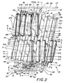
- Fig. 2 is a top plan view of the take-out arbor.
- Fig. 3 is a fragmented sectional view taken substantially along line 3-3 of Fig. 2.
- Fig. 4 is a somewhat schematic end elevational view of the take-out arbor taken substantially along line 4-4 of Fig. 2.
- Fig. 5 is an enlarged sectional view taken substantially along line 5-5 of Fig. 2.
- Fig. 6 is a sectional view taken substantially along line 6-6 of Fig. 2.
- Fig. 7 is a somewhat schematic top plan view of the take-out arbor, similar to Fig. 2, but showing the arbor in a different, adjusted position.
- Fig. 8 is a somewhat schematic top plan view of the take-out arbor, similar to Fig. 7, but showing the arbor in a different, adjusted position.
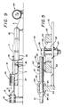
- Fig. 9 is a schematic elevational view of a horizontal strip accumulator having a take-out arbor made in accordance with the concepts of the present invention and shown with an uncoiler, a strip entry twister, a unique turn-around system and a strip exit twisting stand which form the environment for the horizontal strip accumulator.
- Fig. 10 is a schematic top plan view of the horizontal strip accumulator and its associated elements shown in Fig. 9.
- FIG. 1 An accumulator having the novel features of the present invention is depicted schematically in Fig. 1 and indicated generally by the numeral 20.
- a typical environment for accumulator 20 includes an uncoiler, indicated generally by the numeral 21, which has a base 22 and axle 23 upon which a coil 24 of strip material S revolves.
- the strip S which may be of any material and gauge, but which is generally of a metallic material, can be fed through the jaws of an end joiner 25 to accumulator 20.
- End joiner 25 which can be a welding device, is used to join the end of a coil of strip just depleted to a fresh coil placed on uncoiler 21.
- end joiner 25 may be a portable device which is brought in line only when needed.
- the accumulator 20 shown is generally of the type known as a vertical accumulator such as that depicted in detail in U.S. Patent No. 3,506,210, to which reference is made for whatever details might be necessary to fully understand the operation thereof; however, the invention described herein is capable of operating with any type of accumulating device, many of which are well known in the art, such as the horizontal accumulator shown in Figs. 9 and 10 and indicated generally by the numeral 26.
- accumulator 20 includes a generally vertically upstanding rear face or frame 27 which extends upwardly from floor F (Fig. 3) and carries essentially all of the elements of accumulator 20.
- the uncoiler or other device includes an alignment device, such as an edge guide (not shown) for presenting the strip S to the accumulator at a particular position or reference point.
- an edge guide not shown
- the accumulator 20 of the present invention can advantageously receive strip S of any width with only one edge thereof aligned against such a guide, it is to be understood that the strip S may also be fed to accumulator 20 centered, if that is desired.
- the strip is then transferred past guide and support rollers 29, which may also be driven or which may be driven instead of wheels 28, to form an outer loop of strip material, the outer edge of which is defined by a plurality of outer basket rollers 30.
- the material travels around the other basket rollers 30 and forms a free loop 31 as it is turned toward a series of rollers 32 which together form an inner basket or loop of strip material.
- the speed of the strip S into the accumulator 20 is generally faster than the speed of the strip out of the accumulator to the processing line.
- outer convolutions 33 of strip S are accumulated with strip being continually fed to the outside thereof, and inner convolutions 34 of strip S are accumulated by receiving strip from the inside of the outer convolutions 33 by means of the orbiting of loop 31.
- the strip on the inside of the inner convolution 34 is transferred around a take-out arbor assembly, generally indicated by the numeral 35, and then transferred to the processing line.
- a take-out arbor assembly generally indicated by the numeral 35
- the strip will exit accumulator 20 at a reference point different than the reference point established by the edge guide, preferably centered to be received directly by the processing line.
- Take-out arbor assembly 35 includes a main body portion or mandrel, generally indicated by the numeral 36, and a secondary body portion or mandrel, generally indicated by the numeral 37.
- secondary mandrel 37 is rotatable relative to main mandrel 36, which is fixed relative to rotational movement, but both mandrels 36 and 37 are movable together angularly with respect to rear accumulator frame 27.
- arbor 35 is always mounted at an angle, other than 90°, to the path of the strip material S.
- arbor mandrel 36 includes a centrally located, hollow, cylindrical hub 38.
- a rear disk 39 and a front disk 40 are welded to the circumferential outside of hub 38 and are spaced from each other to carry a plurality of spaced slats 41.
- slats 41 define a generally cylindrical outer shell for mandrel 36. While this outer shell could be continuous in nature, slats 41 are preferred not only to reduce the weight of arbor 35, but also, as can be seen particularly in Figs. 7 and 8, because of the requirement that some slats 41 be longer than others for reasons to be hereinafter described.
- Main arbor mandrel 36 is attached to rear frame 27 by a pivot assembly generally indicated by the numeral 42.
- pivot assembly 42 includes a clevis 43 welded to the interior of hub 38 and extending longitudinally outwardly thereof to be received by a trunion 44 carried by rear frame 27.
- a pivot pin 45 extends through clevis 43 and trunion 44, and arbor 35 is thus angularly adjustable with respect to frame 27 by rotation on an axis defined by pin 45.
- Arbor mandrel 37 includes a centrally located, hollow, cylindrical hub 46 which is shorter than hub 38 of mandrel 36 and which, as best shown in Fig. 3, is slidably received around the outside of hub 38.
- a rear disk 47 and front disk 48 are welded to the circumferential outside of hub 46 and are spaced from each other to carry a plurality of spaced slats 49.
- slats 49 define a generally cylindrical outer shell for mandrel 37.
- spaced slats 49 are preferred over a continuous shell to reduce the weight of arbor 35 and to easily accommodate the fact that some of the slats 49 need to be longer than others, as will be hereinafter described.
- Adjustment assembly 50 includes a base plate 52 which extends inwardly from frame 51 and slidably supports a plate 53 having a slot 54 therein. Plate 53 is attached, as by welding, to the inside of hub 46 of arbor mandrel 37 (Fig. 4).
- a guide bushing 55 extends through slot 54 and is held in place by a bolt 56 having a nut 57 and washer 58. Bolt 56 may be welded to plate 52 to in effect make bushing 55 a permanent stud.
- Plate 53 carries a generally cylindrical tube 59 having a radial threaded bore 60 therethrough to receive the threaded end of an adjusting bolt 61.
- a set screw 62 may be provided to hold bolt 61 in place and prevent undesired rotation thereof.
- the unthreaded end of bolt 61 is slidably received through a bore 63 and its associated thrust washers 64, bore 63 being formed in a block 65 carried by base plate 52. The relative position of block 65 and bolt 61 is maintained by lock collars 66.
- arbor 35 has been pivoted counterclockwise from the Fig. 2 position to adjust the angle thereof in the other direction.
- Fig. 2 central or neutral position to accommodate the average or median strip S widths
- smaller and larger strip S widths can be readily received around arbor 35, having been fed to accumulator 20 with a fixed edge, irrespective of the width, but leaving arbor 35 and accumulator 20 with its width center line fixed -- all as more fully described in U.S. Patent No. 3,885,748 to which reference is made, as necessary, for a complete understanding of this invention.
- arbor 35 is preferably positioned at an angle relative to perpendicular to frame 27 of approximately 12.27° (Fig. 2).
- arbor 35 is positioned at an angle of approximately 13.93° from perpendicular (Fig. 7), and for larger strip S widths, such as 15 inches, the angle is reduced to approximately 10.62° from perpendicular (Fig. 8).
- rotation of arbor 35 of less than 3.5° is sufficient to accommodate strip S widths of from 1.5 inches to 15 inches.
- Arbor mandrels 36 and 37 carry a plurality of roller assemblies mounted on slats 41 and 49 in a helical path therearound.
- Each roller assembly includes a roller 67, and ideally the longitudinal direction of each roller 67 should be maintained perpendicular to the path of the strip and thus is approximately 12.27° from the axis of arbor 35 in the median or neutral position.
- rollers 67e, 67j, 67l, 67p, and 67s are shown in Fig. 4 as they would actually appear, that is, angularly mounted, with the rest of the roller assemblies being schematically shown for clarity.
- Each roller 67 is mounted for rotation on a shaft 68 rotatably carried between a rear bracket 69 and a front bracket 70.
- Each rear bracket 69 is mounted on a slat 41 of mandrel 36 and each front bracket 70 is mounted on a slat 49 of mandrel 37.
- the rear longitudinal extent of each roller 67 is carried by mandrel 36, and the front longitudinal extent of each roller 67 is carried by mandrel 37.
- some of the slats 41 and 49 must be longer than other of the slats 41 and 49, as previously described.
- the slats 41 carrying the rear brackets 69 for rollers 67r and 67s are longer than other of the slats 41, and the slats 49 carrying the front brackets 70 for rollers 67a and 67b are longer than other of the slats 49.
- the roller assemblies may be provided with containment bars 71 extending between brackets 69 and 70 and thus running parallel to rollers 67. At start up, the strip S is threaded between rollers 67 and bars 71 to assure that the strip S maintains contact with the rollers 67 as it traverses arbor 35.
- each roller assembly is mounted on arbor mandrel 36 and the other end on arbor mandrel 37, when the angle of arbor 35 is adjusted, as previously described, the rollers 67 would not be properly oriented in total alignment with strip S.
- a roller adjusting assembly generally indicated by the numeral 72, best shown in Fig. 4, and now to be described.
- roller adjusting assembly 72 The main component of roller adjusting assembly 72 is a fork 73 which has an arcuate slot 74 near the bottom thereof which is received around and rides on the outer end of hub 38 of arbor mandrel 36. Spade members 75 extend tangentially downward along the sides of hub 38, and fork 73 is maintained axially on hub 38 by a retaining ring 76 which is held in place as by a set screw 77.
- a generally oval slot 78 is formed near the top of fork 73 to receive a pin 79 that extends outwardly from a flange 80 (Fig. 3) mounted on front frame 51.
- An enlarged head 81 on pin 79 maintains fork 73 on pin 79 between flange 80 and head 81.
- the shaft 68 of one of the rollers is extended, as at end 82, through its front bracket 70.
- Shaft end 82 extends through spherical bearings 83 positioned in the body of fork 73 between hub 38 and pin 79.
- both the desired angular orientation of arbor 35 and the desired angular orientation of rollers 67 is accomplished.
- pin 79 is directly radially above hubs 38 and 46, and the point that the end 82 of shaft 68 extends through fork 73 is offset therefrom by approximately 7.92° (Fig. 4).
- the outer end of arbor 35 is moved to the right, as shown in Fig. 7, hub 46 having rotated approximately 3.09° clockwise as the angle shown in Fig. 4 becomes approximately 11.01°, thereby moving the front ends of all of the rollers to the left as viewed in Fig. 7.
- the adjustable arbor provides even more improvements for the horizontal accumulator 26 shown in Figs. 9 and 10.
- Accumulator 26 is depicted in the environment of a processing line which includes a conventional uncoiler 84, which can be identical to uncoiler 21.
- Uncoiler 84 provides strip S to a conventional strip entry twister 85 which turns strip S on its edge, that is, with its width dimension in a plane perpendicular to the floor. As so oriented, strip S passes through driven pinch rolls 86 and into accumulator 26.
- accumulator 26 operates essentially identically to accumulator 20 except that basically all of its parts are oriented 90° to those in accumulator 20.
- rear frame 27 of accumulator 20 is replaced by a horizontally oriented base or table 87 which supports essentially all of the elements of accumulator 26.
- Strip S entering accumulator 26 forms outer strip convolutions 88, the strip on the inside of which is fed to inner strip convolutions 89 supported by rollers 90.
- the strip on the inside of convolutions 89 is transferred to and around arbor 35 which is adjustable identically as when it is used in accumulator 20.
- arbor 35 thus provide its exiting strip S properly aligned, but is also particularly advantageous in a horizontal accumulator because the exiting strip S has its edge parallel to the floor as opposed to the rising exiting strip which has plagued conventional horizontal accumulators.
- strip S exits accumulator 26 traveling in the same direction as it was when it entered accumulator 26.
- a turnaround device 91 which includes entry rollers 92 and turnaround rollers 93 which direct strip S to exit rollers 94 and out in a different direction preferably back over the top of accumulator 26 as shown.
- a conventional exit twisting stand 95 may be provided to twist strip S 90° so that its width plane is parallel to the floor -- its appropriate orientation for receipt by the processing line. It should thus be appreciated that the twisting can take place over the top of accumulator 26, thereby saving valuable floor space which would otherwise have been required to effect the twisting. Moreover, because strip S is not rising after it leaves accumulator 26, the twisting action can begin to take place immediately rather than waiting until the strip reaches its summit.
- a take-out arbor made in accordance with the concepts of the present invention not only automatically provides strip material at its desired position for the processing, being guided around the arbor over adjustable rollers, but also can be utilized in both vertically oriented and horizontally oriented accumulators. When used in horizontal accumulators, a unique floor-saving system can be employed.
- the arbor, as well as the vertical and horizontal accumulators described herein, thus accomplish the objects of the present invention and otherwise substantially improve the strip processing art.
Landscapes
- Engineering & Computer Science (AREA)
- Mechanical Engineering (AREA)
- Advancing Webs (AREA)
- Details Of Rigid Or Semi-Rigid Containers (AREA)
- Packaging Of Machine Parts And Wound Products (AREA)
- Winding, Rewinding, Material Storage Devices (AREA)
- Replacement Of Web Rolls (AREA)
Applications Claiming Priority (2)
| Application Number | Priority Date | Filing Date | Title |
|---|---|---|---|
| US80916 | 1993-06-22 | ||
| US08/080,916 US5443221A (en) | 1993-06-22 | 1993-06-22 | Take-out arbor for a strip accumulator |
Publications (2)
| Publication Number | Publication Date |
|---|---|
| EP0630698A1 true EP0630698A1 (fr) | 1994-12-28 |
| EP0630698B1 EP0630698B1 (fr) | 1997-09-10 |
Family
ID=22160479
Family Applications (1)
| Application Number | Title | Priority Date | Filing Date |
|---|---|---|---|
| EP94304486A Expired - Lifetime EP0630698B1 (fr) | 1993-06-22 | 1994-06-21 | Arbre de prise d'accumulateur de feuillard |
Country Status (5)
| Country | Link |
|---|---|
| US (1) | US5443221A (fr) |
| EP (1) | EP0630698B1 (fr) |
| AT (1) | ATE157915T1 (fr) |
| CA (1) | CA2122692A1 (fr) |
| DE (1) | DE69405475T2 (fr) |
Families Citing this family (4)
| Publication number | Priority date | Publication date | Assignee | Title |
|---|---|---|---|---|
| US5529257A (en) * | 1995-03-16 | 1996-06-25 | Abbey Etna Machine Company | Strip accumulator |
| KR100313474B1 (ko) * | 1999-04-13 | 2001-11-15 | 원웅재 | 로터리식 루퍼 |
| DE10030606A1 (de) * | 2000-06-21 | 2002-01-03 | Sms Demag Ag | Bandspeicher für Metallbänder, insbesondere Spiralbandspeicher für dickere Stahlbänder |
| ES2686371T3 (es) * | 2013-01-24 | 2018-10-17 | Cockerill Maintenance & Ingenierie S.A. | Acumulador de banda horizontal con carros de soporte de banda delgados y sistema central pasivo de enganche |
Citations (7)
| Publication number | Priority date | Publication date | Assignee | Title |
|---|---|---|---|---|
| US3506210A (en) * | 1967-10-20 | 1970-04-14 | Armco Steel Corp | Compact strip accumulator |
| US3628742A (en) * | 1970-07-08 | 1971-12-21 | Armco Steel Corp | Drive system for strip accumulator |
| US3885748A (en) * | 1974-03-28 | 1975-05-27 | Loopco Industries | Take-out arbor for a strip accumulator |
| JPS59163010A (ja) * | 1983-03-09 | 1984-09-14 | Ishikawajima Harima Heavy Ind Co Ltd | ストリツプ方向転換装置 |
| EP0129209A2 (fr) * | 1983-06-16 | 1984-12-27 | Dr. Weusthoff GmbH | Machine d'accumulation de bandes |
| JPS62240107A (ja) * | 1986-04-11 | 1987-10-20 | Ishikawajima Harima Heavy Ind Co Ltd | ストリツプ貯留装置 |
| EP0389085A1 (fr) * | 1989-03-20 | 1990-09-26 | Ceeco Machinery Manufacturing Company Limited | Dispositif équilibré en continu pour stockage et distribution de matière |
Family Cites Families (4)
| Publication number | Priority date | Publication date | Assignee | Title |
|---|---|---|---|---|
| US3310255A (en) * | 1964-11-09 | 1967-03-21 | Sendzimir Inc T | Spiral looper |
| US4506841A (en) * | 1982-09-29 | 1985-03-26 | Kent Corporation | Arbor for a strip accumulator |
| US4529140A (en) * | 1983-06-23 | 1985-07-16 | Guild International Inc. | Continuous strip accumulator |
| US4557427A (en) * | 1984-10-15 | 1985-12-10 | Interlake, Inc. | Powered strap accumulator |
-
1993
- 1993-06-22 US US08/080,916 patent/US5443221A/en not_active Expired - Fee Related
-
1994
- 1994-05-02 CA CA002122692A patent/CA2122692A1/fr not_active Abandoned
- 1994-06-21 DE DE69405475T patent/DE69405475T2/de not_active Expired - Fee Related
- 1994-06-21 AT AT94304486T patent/ATE157915T1/de not_active IP Right Cessation
- 1994-06-21 EP EP94304486A patent/EP0630698B1/fr not_active Expired - Lifetime
Patent Citations (7)
| Publication number | Priority date | Publication date | Assignee | Title |
|---|---|---|---|---|
| US3506210A (en) * | 1967-10-20 | 1970-04-14 | Armco Steel Corp | Compact strip accumulator |
| US3628742A (en) * | 1970-07-08 | 1971-12-21 | Armco Steel Corp | Drive system for strip accumulator |
| US3885748A (en) * | 1974-03-28 | 1975-05-27 | Loopco Industries | Take-out arbor for a strip accumulator |
| JPS59163010A (ja) * | 1983-03-09 | 1984-09-14 | Ishikawajima Harima Heavy Ind Co Ltd | ストリツプ方向転換装置 |
| EP0129209A2 (fr) * | 1983-06-16 | 1984-12-27 | Dr. Weusthoff GmbH | Machine d'accumulation de bandes |
| JPS62240107A (ja) * | 1986-04-11 | 1987-10-20 | Ishikawajima Harima Heavy Ind Co Ltd | ストリツプ貯留装置 |
| EP0389085A1 (fr) * | 1989-03-20 | 1990-09-26 | Ceeco Machinery Manufacturing Company Limited | Dispositif équilibré en continu pour stockage et distribution de matière |
Non-Patent Citations (2)
| Title |
|---|
| PATENT ABSTRACTS OF JAPAN vol. 12, no. 109 (M - 682) 1988 * |
| PATENT ABSTRACTS OF JAPAN vol. 9, no. 14 (M - 352) 1985 * |
Also Published As
| Publication number | Publication date |
|---|---|
| DE69405475T2 (de) | 1998-01-15 |
| EP0630698B1 (fr) | 1997-09-10 |
| ATE157915T1 (de) | 1997-09-15 |
| US5443221A (en) | 1995-08-22 |
| DE69405475D1 (de) | 1997-10-16 |
| CA2122692A1 (fr) | 1994-12-23 |
Similar Documents
| Publication | Publication Date | Title |
|---|---|---|
| US6688076B1 (en) | Apparatus for wrapping articles in film material | |
| DE4403330C2 (de) | Automatische Längsschneide- und Wiederaufwickelmaschine | |
| US4770366A (en) | System for supplying strip to a processing line | |
| US5116043A (en) | Method of and apparatus for winding square folded sheet-like products on a rotary core | |
| JPS58125553A (ja) | シ−ト状物質をロ−ルに巻き取るタ−レツト型巻取機および方法 | |
| US3885748A (en) | Take-out arbor for a strip accumulator | |
| JP3453359B2 (ja) | 合成フィラメント用巻取機 | |
| US5720444A (en) | Strip accumulators | |
| US4374575A (en) | Winding machine for continuously winding strips of web material into rolls | |
| EP0630698B1 (fr) | Arbre de prise d'accumulateur de feuillard | |
| US4358064A (en) | Pipe wrapping machine | |
| CA2007970C (fr) | Appareil equilibre pour le stockage et l'alimentation de materiel en bandes | |
| US4538397A (en) | Method and apparatus for storage of paper sheets and the like | |
| US4505438A (en) | Single coil accumulator | |
| US4102511A (en) | Turret for winders and unwinders | |
| CA1235107A (fr) | Machine de stockage de bandes | |
| US5529257A (en) | Strip accumulator | |
| US5330119A (en) | Automated uncoiling apparatus | |
| KR102702626B1 (ko) | 지관 제조 장치 및 이를 사용하여 지관을 제조하는 방법 | |
| CN109661280B (zh) | 用于转向卷取机的支撑装置以及卷取设备 | |
| US4986484A (en) | Method to store filiform products and relative device to store filiform products | |
| US4523421A (en) | Method and apparatus for wrapping metal coil | |
| US5601250A (en) | Strip accumulator | |
| US6213423B1 (en) | Self-lifting shaftless unwind stand | |
| KR102530864B1 (ko) | 태선용 벨트 그라인더 시스템 |
Legal Events
| Date | Code | Title | Description |
|---|---|---|---|
| PUAI | Public reference made under article 153(3) epc to a published international application that has entered the european phase |
Free format text: ORIGINAL CODE: 0009012 |
|
| AK | Designated contracting states |
Kind code of ref document: A1 Designated state(s): AT BE DE FR GB IT |
|
| 17P | Request for examination filed |
Effective date: 19941208 |
|
| 17Q | First examination report despatched |
Effective date: 19960329 |
|
| GRAG | Despatch of communication of intention to grant |
Free format text: ORIGINAL CODE: EPIDOS AGRA |
|
| GRAH | Despatch of communication of intention to grant a patent |
Free format text: ORIGINAL CODE: EPIDOS IGRA |
|
| GRAH | Despatch of communication of intention to grant a patent |
Free format text: ORIGINAL CODE: EPIDOS IGRA |
|
| GRAA | (expected) grant |
Free format text: ORIGINAL CODE: 0009210 |
|
| AK | Designated contracting states |
Kind code of ref document: B1 Designated state(s): AT BE DE FR GB IT |
|
| REF | Corresponds to: |
Ref document number: 157915 Country of ref document: AT Date of ref document: 19970915 Kind code of ref document: T |
|
| REF | Corresponds to: |
Ref document number: 69405475 Country of ref document: DE Date of ref document: 19971016 |
|
| ITF | It: translation for a ep patent filed | ||
| ET | Fr: translation filed | ||
| PGFP | Annual fee paid to national office [announced via postgrant information from national office to epo] |
Ref country code: FR Payment date: 19980609 Year of fee payment: 5 |
|
| PGFP | Annual fee paid to national office [announced via postgrant information from national office to epo] |
Ref country code: GB Payment date: 19980612 Year of fee payment: 5 |
|
| PGFP | Annual fee paid to national office [announced via postgrant information from national office to epo] |
Ref country code: AT Payment date: 19980615 Year of fee payment: 5 |
|
| PGFP | Annual fee paid to national office [announced via postgrant information from national office to epo] |
Ref country code: DE Payment date: 19980629 Year of fee payment: 5 |
|
| PLBE | No opposition filed within time limit |
Free format text: ORIGINAL CODE: 0009261 |
|
| STAA | Information on the status of an ep patent application or granted ep patent |
Free format text: STATUS: NO OPPOSITION FILED WITHIN TIME LIMIT |
|
| PGFP | Annual fee paid to national office [announced via postgrant information from national office to epo] |
Ref country code: BE Payment date: 19980813 Year of fee payment: 5 |
|
| 26N | No opposition filed | ||
| PG25 | Lapsed in a contracting state [announced via postgrant information from national office to epo] |
Ref country code: GB Free format text: LAPSE BECAUSE OF NON-PAYMENT OF DUE FEES Effective date: 19990621 Ref country code: AT Free format text: LAPSE BECAUSE OF NON-PAYMENT OF DUE FEES Effective date: 19990621 |
|
| PG25 | Lapsed in a contracting state [announced via postgrant information from national office to epo] |
Ref country code: FR Free format text: THE PATENT HAS BEEN ANNULLED BY A DECISION OF A NATIONAL AUTHORITY Effective date: 19990630 Ref country code: BE Free format text: LAPSE BECAUSE OF NON-PAYMENT OF DUE FEES Effective date: 19990630 |
|
| BERE | Be: lapsed |
Owner name: KENT CORP. Effective date: 19990630 |
|
| GBPC | Gb: european patent ceased through non-payment of renewal fee |
Effective date: 19990621 |
|
| PG25 | Lapsed in a contracting state [announced via postgrant information from national office to epo] |
Ref country code: DE Free format text: LAPSE BECAUSE OF NON-PAYMENT OF DUE FEES Effective date: 20000503 |
|
| REG | Reference to a national code |
Ref country code: FR Ref legal event code: ST |
|
| PG25 | Lapsed in a contracting state [announced via postgrant information from national office to epo] |
Ref country code: IT Free format text: LAPSE BECAUSE OF NON-PAYMENT OF DUE FEES Effective date: 20050621 |