EP0630717A1 - Cisaille avec réglage de l'angle de la lame - Google Patents
Cisaille avec réglage de l'angle de la lame Download PDFInfo
- Publication number
- EP0630717A1 EP0630717A1 EP94108634A EP94108634A EP0630717A1 EP 0630717 A1 EP0630717 A1 EP 0630717A1 EP 94108634 A EP94108634 A EP 94108634A EP 94108634 A EP94108634 A EP 94108634A EP 0630717 A1 EP0630717 A1 EP 0630717A1
- Authority
- EP
- European Patent Office
- Prior art keywords
- arm
- frame
- angle
- shear blade
- shaft
- Prior art date
- Legal status (The legal status is an assumption and is not a legal conclusion. Google has not performed a legal analysis and makes no representation as to the accuracy of the status listed.)
- Withdrawn
Links
- 238000010008 shearing Methods 0.000 title claims abstract description 51
- 229910000746 Structural steel Inorganic materials 0.000 claims abstract description 53
- 230000000712 assembly Effects 0.000 claims description 11
- 238000000429 assembly Methods 0.000 claims description 11
- XEEYBQQBJWHFJM-OUBTZVSYSA-N iron-52 Chemical compound [57Fe] XEEYBQQBJWHFJM-OUBTZVSYSA-N 0.000 description 18
- 238000005520 cutting process Methods 0.000 description 13
- 238000004080 punching Methods 0.000 description 10
- 238000000034 method Methods 0.000 description 6
- 230000008569 process Effects 0.000 description 6
- 230000008859 change Effects 0.000 description 4
- 230000000694 effects Effects 0.000 description 3
- 239000000463 material Substances 0.000 description 3
- 230000007246 mechanism Effects 0.000 description 3
- 230000006835 compression Effects 0.000 description 2
- 238000007906 compression Methods 0.000 description 2
- 239000002184 metal Substances 0.000 description 2
- 229910052751 metal Inorganic materials 0.000 description 2
- 239000000203 mixture Substances 0.000 description 2
- 230000000717 retained effect Effects 0.000 description 2
- 229910000831 Steel Inorganic materials 0.000 description 1
- 230000007423 decrease Effects 0.000 description 1
- 238000009434 installation Methods 0.000 description 1
- 238000004519 manufacturing process Methods 0.000 description 1
- 238000005555 metalworking Methods 0.000 description 1
- 238000012986 modification Methods 0.000 description 1
- 230000004048 modification Effects 0.000 description 1
- 239000010959 steel Substances 0.000 description 1
Images










Classifications
-
- B—PERFORMING OPERATIONS; TRANSPORTING
- B23—MACHINE TOOLS; METAL-WORKING NOT OTHERWISE PROVIDED FOR
- B23D—PLANING; SLOTTING; SHEARING; BROACHING; SAWING; FILING; SCRAPING; LIKE OPERATIONS FOR WORKING METAL BY REMOVING MATERIAL, NOT OTHERWISE PROVIDED FOR
- B23D31/00—Shearing machines or shearing devices covered by none or more than one of the groups B23D15/00 - B23D29/00; Combinations of shearing machines
-
- B—PERFORMING OPERATIONS; TRANSPORTING
- B23—MACHINE TOOLS; METAL-WORKING NOT OTHERWISE PROVIDED FOR
- B23D—PLANING; SLOTTING; SHEARING; BROACHING; SAWING; FILING; SCRAPING; LIKE OPERATIONS FOR WORKING METAL BY REMOVING MATERIAL, NOT OTHERWISE PROVIDED FOR
- B23D23/00—Machines or devices for shearing or cutting profiled stock
-
- Y—GENERAL TAGGING OF NEW TECHNOLOGICAL DEVELOPMENTS; GENERAL TAGGING OF CROSS-SECTIONAL TECHNOLOGIES SPANNING OVER SEVERAL SECTIONS OF THE IPC; TECHNICAL SUBJECTS COVERED BY FORMER USPC CROSS-REFERENCE ART COLLECTIONS [XRACs] AND DIGESTS
- Y10—TECHNICAL SUBJECTS COVERED BY FORMER USPC
- Y10T—TECHNICAL SUBJECTS COVERED BY FORMER US CLASSIFICATION
- Y10T83/00—Cutting
- Y10T83/808—Two tool pairs, driver for one pair moves relative to driver for other pair
- Y10T83/822—Punch and shear
-
- Y—GENERAL TAGGING OF NEW TECHNOLOGICAL DEVELOPMENTS; GENERAL TAGGING OF CROSS-SECTIONAL TECHNOLOGIES SPANNING OVER SEVERAL SECTIONS OF THE IPC; TECHNICAL SUBJECTS COVERED BY FORMER USPC CROSS-REFERENCE ART COLLECTIONS [XRACs] AND DIGESTS
- Y10—TECHNICAL SUBJECTS COVERED BY FORMER USPC
- Y10T—TECHNICAL SUBJECTS COVERED BY FORMER US CLASSIFICATION
- Y10T83/00—Cutting
- Y10T83/869—Means to drive or to guide tool
- Y10T83/8798—With simple oscillating motion only
- Y10T83/8799—Plural tool pairs
- Y10T83/8801—Plural tools on single oscillating arm [i.e., tool holder]
-
- Y—GENERAL TAGGING OF NEW TECHNOLOGICAL DEVELOPMENTS; GENERAL TAGGING OF CROSS-SECTIONAL TECHNOLOGIES SPANNING OVER SEVERAL SECTIONS OF THE IPC; TECHNICAL SUBJECTS COVERED BY FORMER USPC CROSS-REFERENCE ART COLLECTIONS [XRACs] AND DIGESTS
- Y10—TECHNICAL SUBJECTS COVERED BY FORMER USPC
- Y10T—TECHNICAL SUBJECTS COVERED BY FORMER US CLASSIFICATION
- Y10T83/00—Cutting
- Y10T83/869—Means to drive or to guide tool
- Y10T83/8798—With simple oscillating motion only
- Y10T83/8804—Tool driver movable relative to tool support
- Y10T83/8809—Fixed axis lever
-
- Y—GENERAL TAGGING OF NEW TECHNOLOGICAL DEVELOPMENTS; GENERAL TAGGING OF CROSS-SECTIONAL TECHNOLOGIES SPANNING OVER SEVERAL SECTIONS OF THE IPC; TECHNICAL SUBJECTS COVERED BY FORMER USPC CROSS-REFERENCE ART COLLECTIONS [XRACs] AND DIGESTS
- Y10—TECHNICAL SUBJECTS COVERED BY FORMER USPC
- Y10T—TECHNICAL SUBJECTS COVERED BY FORMER US CLASSIFICATION
- Y10T83/00—Cutting
- Y10T83/869—Means to drive or to guide tool
- Y10T83/8798—With simple oscillating motion only
- Y10T83/8812—Cutting edge in radial plane
- Y10T83/8814—Adjustable
-
- Y—GENERAL TAGGING OF NEW TECHNOLOGICAL DEVELOPMENTS; GENERAL TAGGING OF CROSS-SECTIONAL TECHNOLOGIES SPANNING OVER SEVERAL SECTIONS OF THE IPC; TECHNICAL SUBJECTS COVERED BY FORMER USPC CROSS-REFERENCE ART COLLECTIONS [XRACs] AND DIGESTS
- Y10—TECHNICAL SUBJECTS COVERED BY FORMER USPC
- Y10T—TECHNICAL SUBJECTS COVERED BY FORMER US CLASSIFICATION
- Y10T83/00—Cutting
- Y10T83/929—Tool or tool with support
- Y10T83/9457—Joint or connection
- Y10T83/9488—Adjustable
Definitions
- This invention relates to a machine having a blade on a pivotally mounted arm for shearing metal workpieces, including flat bar or plate.
- Machine shops, structural steel plants, manufacturing facilities, and the like may employ machines for shearing metal workpieces, such as steel stock of various shapes and sizes.
- One type of machine commonly known as an “ironworker” or “universal steelworker”, performs four or five different metal working processes on workpieces at four or five separate stations.
- an ironworker or “universal steelworker”
- punching station for punching holes or other shapes
- a notching station for notching the edge of a workpiece
- a bar stock shearing station for shearing lengths of round or square bars
- an angle iron section shearing station for cutting angle iron
- a flat stock shearing station for cutting flat bar or plate.
- the ironworker machine employs a single, large arm or beam 12 which is pivotally mounted to the frame and which is operated with a hydraulic piston and cylinder actuator.
- the various stations such as a punching station 52, a flat stock shearing station 48, an angle cutting station 74, and a notching station 54, are defined at various locations along the length of the pivotally mounted beam.
- a shear machine In addition to cutting flat stock, a shear machine should desirably have the capability for cutting angle iron. In order to cut angle iron with a single, moving blade, both legs of the angle iron must be cut by the blade substantially simultaneously and symmetrically so as to avoid binding.
- Conventional ironworker machines typically have separate stations for angle shearing and plate shearing as discussed above. With a pivoting beam machine, separate stations are normally used for flat plate and angle iron because the angle iron shearing station requires the moving blade to be moved through the angle iron legs at only a very small oblique angle -- preferably as close as possible to a 0° angle -- while the flat stock is much more easily sheared with one of the blades at a significant angle to provide a "scissors" cutting effect.
- the blades at the angle iron shearing station are arranged so that the shearing blade moves at only a small an angle as possible through the legs of the angle iron; however, the blades of the flat stock shearing station are arranged so that the moving blade shears the flat stock at a sufficient angle.
- the present invention provides an improved apparatus for shearing flat stock with an adjustable angle blade, and in the preferred form, the improved apparatus accommodates the selective shearing of angle iron and flat stock at a common receiving station.
- An apparatus in accordance with the teachings of the present invention provides a novel system for adjusting the angle of a shearing blade.
- the apparatus includes a frame which defines a receiving station for receiving flat stock.
- the receiving station has a stationary shear blade assembly having at least one shearing edge.
- An arm assembly includes a first arm pivotally mounted to the frame about a first pivot axis.
- the arm assembly includes a second arm mounted to the first arm for pivoting movement about a second axis.
- the second arm includes a movable shear blade assembly defining at least one shearing edge.
- An actuator is mounted on the frame for pivoting the arm assembly about the first pivot axis between an open position in which the movable and stationary shear blade assemblies are spaced apart and a closed position in which the shear blade assemblies are closer together.
- the second arm defines a guide way
- the frame has a guide member which is selectively positionable relative to the first axis for slidably engaging the guide way to pivot the second arm about the second axis. This results in the orientation of the movable shear blade relative to the stationary shear blade changing in a predetermined relationship as the arm assembly pivots between the open and closed positions.
- the apparatus is adapted for selectively shearing angle iron and flat stock at a common receiving station.
- the frame defines the common receiving station for separately receiving the angle iron and flat stock.
- the receiving station includes a stationary shear blade assembly having two shearing edges extending from a vertex to define a generally 90° angle inside corner.
- An arm assembly includes a first arm pivotally mounted to the frame about a first pivot axis.
- the arm assembly includes a second arm mounted to the first arm for pivoting movement about a second pivot axis.
- the second arm includes a movable shear blade assembly having two shearing edges directed outwardly to define a generally 90° angle outside corner.
- An actuator is mounted on the frame for pivoting the arm assembly about the first pivot axis between an open position in which the movable and stationary shear blade assemblies are spaced apart and a closed position in which the shear blade assemblies are in an overlapped, adjacent configuration.
- the second arm defines a guide way
- the frame has a guide member which is selectively positionable relative to the first axis for slidably engaging the guide way to pivot the second arm about the second pivot axis. This results in the orientation of the movable shear blade relative to the stationary shear blade changing in a predetermined relationship as the arm assembly pivots between the open and closed positions.
- the apparatus of this invention is described in the normal (upright) operating position, and terms such as upper, lower, horizontal, etc., are used with reference to this position. It will be understood, however, that the apparatus of this invention may be manufactured, stored, transported, and sold in an orientation other than the position described.
- FIG. 1 A novel ironworker type of machine tool apparatus in accordance with the present invention is illustrated in FIG. 1 and is designated generally therein by the reference numeral 20.
- the apparatus 20 has a frame that includes a front cover or wall 22 and a rear cover or wall 24.
- a main pivoting beam or first arm 26 is pivotally mounted to the frame walls 22 and 24 with a central bearing assembly 28 for pivoting about a first axis 30 (FIG. 5).
- This assembly 28 may be of any suitable conventional or special design, the details of which form no part of the present invention.
- the punching station 32 and the notching station 36 are operated by pivoting the main arm 26 counterclockwise or clockwise, respectively, in a well known manner.
- a pair of links 38 are pivotally connected to the right-hand end of the arm 26, just inwardly of the notching station 36, via a pin or shaft 40 as shown in FIGS. 1 and 7.
- the lower end of each link 38 is pivotally connected with a pin or shaft 42 to a crank arm 44 which is pivotally mounted to the frame with a pivot pin or shaft 46.
- a lower end of crank arm 44 (not visible in FIG. 1) is pivotally connected to a conventional, double acting, hydraulic, piston-cylinder actuator (not visible in FIG. 1) for pivoting the crank arm 44 about the pivot shaft 46 in a selected direction of rotation as indicated by the double headed arrow 48.
- the main arm 26 pivots counterclockwise or clockwise on the main bearing 28 to effect the punching process at the punching station 32 or the notching process at the notching station 36.
- the use of a double-acting piston-cylinder actuator to pivot a main arm for operating a punching station or a notching station is well known in the art. For example, see the machine design illustrated in U.S. Patent No. 3,866,522.
- the frame defines a common receiving station 50 for separately receiving a piece of angle iron or flat stock.
- FIG. 8 illustrates a section of angle iron 52 in the receiving station 50
- FIG. 12 illustrates a flat stock bar or plate 54 in the receiving station 50.
- the apparatus frame defines an opening through the apparatus at the receiving station to accommodate the workpiece (i.e., angle iron or plate).
- the frame front wall 22 defines such an opening 56 in conjunction with the rear wall 24.
- the receiving station 50 includes a stationary shear blade assembly comprising a first stationary blade 61, and second stationary blade 62, a third stationary blade 63, and a fourth stationary blade 64.
- the third stationary blade 63 has an edge 65
- the fourth stationary blade 64 has an edge 67.
- the blade edges 65 and 67 extend from a vertex to define a generally 90° angle inside corner.
- the tops of the stationary blades 62 and 61 define a horizontal blade edge continuing from the shear edge 65.
- the blades 61, 62, 63, and 64 are removably mounted to the frame with bolts 68 to conventional blade holder assemblies 71, 72, and 73 which are mounted on the frame front wall 22.
- a movable blade assembly comprises a first blade 81 and a second blade 82 which are mounted to a second arm 84 carried on the first arm 26.
- the movable shear blade assembly second blade 82 has two shearing edges, edges 86 and 88, which are directed outwardly to define a generally 90° angle outside corner.
- the edge of blade 81 defines a continuation of the shear edge 86.
- the moving shear blade 82 is removably mounted with bolts 90 to the second arm 84.
- the blade 81 is similarly bolted to the second arm 84 as illustrated in FIG. 3.
- the second arm 84 is mounted for pivoting movement on the first arm 26 as illustrated in FIG. 3.
- the first arm 26 defines a bore 102 in which is received a rotatable shaft 104.
- a cylindrical bearing 106 is preferably provided in the bore 102 around the shaft 104 to accommodate rotation of the shaft 104 within the bore 102.
- the shaft 104 includes a reduced diameter front portion 108 which is received in a bore 110 defined by the second arm 84.
- the shaft 104 is held in place by a rear retainer plate 114 which is secured with a plurality of bolts 116.
- the bolts 116 each pass through a bore 120 in the shaft 104 and are threadingly engaged with bores 124 defined in the second arm 84.
- the rear cover plate 114, bolts 116, second arm 84, and the shaft 104 are thus all fixed together for rotation together about the shaft axis relative to the first arm 26.
- the upper end of the second arm 84 can be adjustably guided relative to the first arm pivot axis 30 (FIG. 5).
- the second arm 84 defines a guide way in the form of a slot 128 which receives a guide member in the form of a pin 132 extending inwardly from an adjustment mechanism on the frame front wall 22.
- the projection of the pin 132 from the adjustment block 134 is accommodated by a generally horizontally disposed slot 135 in the frame wall 22 (FIGS. 1, 4, and 5).
- the adjustment mechanism includes a block 134 (FIGS. 1, 4, and 4A) defining a bore 136 (FIG. 4) receiving an end of the pin 132.
- the block 134 is slidably disposed between a pair of spaced-apart guide bars or tracks 138 (FIGS. 2-4) mounted to the frame front wall 22.
- a pair of retainer bars 142 (FIGS. 1-4) are secured with bolts 144 to the tracks 138 and extend inwardly over margins of the adjustment block 134 to retain the block 134 within the tracks 138.
- the adjustment block 134 is connected to an adjustment shaft 148. As shown in FIG. 4A, the adjustment shaft 148 has an enlarged distal end 150 which is captured with an end block 152 connected to the adjustment block 134. The shaft 148 is free to rotate about its longitudinal axis relative to the adjustment block 134, and the shaft 148 functions to move the adjustment block 134 linearly to a selected position within the guide tracks 138.
- the shaft 148 is threaded and is attached at its distal end to a hand wheel 156 (FIG. 1).
- the shaft 148 is supported on the frame near the handle with a threaded bracket 158.
- the shaft 148 is threadingly engaged with the threaded bracket 158.
- turning the hand wheel 156 causes the threaded shaft 148 to move linearly in one direction or the other along the frame so as to move the adjustment block 134, and pin 132 mounted therein, along the guide tracks 138.
- the pin 132 can be positioned at a selected location relative to the pivot axes of the first arm 26 and second arm 84.
- movement of the pin 132 to the right will cause the arm 84 to pivot clockwise relative to the pivot axis defined by the mounting shaft 108.
- movement of the pin 132 to the left will cause the second arm 84 pivot in the counterclockwise direction.
- the second arm 84 adjustment capability permits the movable shear blade assembly (blades 81 and 82) to be initially positioned at a selected angle that is most appropriate for cutting a particular workpiece.
- the desired angle depends upon the shape, size, and material of the workpiece.
- the single receiving station 50 can be employed for shearing angle iron as well as flat stock with the movable blade assembly oriented at an appropriate angle.
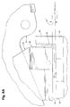
- FIGS. 8 and 8A illustrate the beginning of the process for shearing the structural steel angle 52.
- the adjustment member 134 has been moved forwardly with the shaft 148 to position the guide member pin 132 at a location which pivots the arm 84 so that the edges of the movable blades 81 and 82 define a very small angle, about 0.1° relative to the opposing edges of the stationary blade assembly blade 61, 62, and 63.
- This angle is measured when the arms are at the top of the normal stroke providing sufficient clearance for positioning of an angle iron having 9.525 mm (3/8") thick legs.
- the top of stroke blade angle would be slightly more or less, respectively, than the 0.1° angle shown.
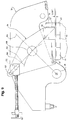
- FIGS. 9 and 9A illustrate the positions of the components where the movable shear blade 82 has just contacted the angle iron 52.
- the angle between the bottom of the movable blade 82 and the top edges of the stationary blades 61, 62 and 63 is 0.008° -- and this is very close to 0°.
- the vertical edge of the movable shear blade 82 is substantially parallel to the vertical leg of the angle iron 52
- the bottom, horizontal edge of the movable shear blade 82 is substantially parallel to the horizontal leg of the angle iron 52. Both legs of the angle iron 52 are essentially contacted substantially simultaneously by the edges of the movable shear blade 82.
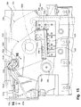
- FIGS. 10 and 10A illustrate the position of the movable shear blade 82 after a substantial thickness of the angle iron 52 has been penetrated, and the angle between the movable blades 81 and 82 on one hand and the stationary blades 61, 62, and 63 on the other hand is 0°. That is, the bottom edges of the movable shear blades 81 and 82 are substantially parallel to the top edges of the stationary shear blades 61, 62, and 63. For a 9.525 mm (3/8") thick angle iron 52, this position may be characterized as the "design basis" position.
- the bottom edges of the movable shear blades 81 and 82 are about 6.35 mm (1/4") above the top edges of the stationary blades 61, 62, and 63.
- This design basis arrangement wherein the upper, movable shear blades are substantially parallel to the lower, stationary blades when the spacing between the movable blades and stationary blades is 6.35 mm (1/4"), functions satisfactorily for various angle iron thicknesses ranging between about 9.525 mm (3/8") maximum thickness and about 3.175 mm (1/8") minimum thickness.
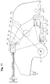
- FIGS. 11 and 11A illustrate this overlap and show that the movable shear blade assembly has now become tilted in the opposite direction. That is, the angle defined by the movable blades and the stationary blades has now reversed, or become negative. For the selected bottom of stroke position, the angle is about - 0.4°.
- the angle of the blade 82 relative to the stationary blades changes very little and is substantially 0°.
- the initial contact angle is 0.008°, and the angle becomes 0° as the blade 82 moves part way through the angle iron 52.
- the angle becomes slightly negative as the blade passes completely through the angle iron 52.
- the movable blade 82 moves through the angle iron 52 with the blade vertical edge substantially parallel to the angle iron vertical leg and with the blade horizontal edge substantially parallel to the angle iron horizontal leg.
- the legs of the angle iron 52 are cut substantially simultaneously and without significant binding.
- the pivot axis of the second arm 84 follows a circular arc path 160 (FIGS. 8, 9, 10, and 11).
- the radius of the arc path 160 (as defined between the arc path 160 and the first arm pivot axis in the bearing 28) is relatively large.
- the arc length traveled by the second arm 84 during the shearing process is relatively small.
- the corner or tip of the movable shear blade 82 moves along a path that is very close to being straight.
- the components are arranged so that the tip of the blade 82 moves along a large radius arc path that substantially corresponds to a straight line 162 (FIGS. 8, 9, 10, and 11) which bisects the vertex of the 90° inside corner angle of the stationary shear blade assembly.
- a straight line 162 (FIGS. 8, 9, 10, and 11) which bisects the vertex of the 90° inside corner angle of the stationary shear blade assembly.
- the line 162 also bisects the 90° outside corner angle defined by the movable shear blade 82 and passes through the pivot axis of the second arm 84 and through the center of the pin 132.
- the longitudinal axis of the arm slot 128 is a straight line 163 (FIGS. 12, 13, and 14) that passes through the center of the pin 132, through the second arm pivot axis, and through the vertex of the 90° angle outside corner of the shear blade 82.
- the fixed line 162 bisecting the 90° angle inside corner of the stationary shear blade assembly is substantially coincident with the straight line 163. Accordingly, in FIGS. 8-11, these two substantially coincident lines are shown as the one line 162.
- a straight line 164 can be drawn perpendicular to the line 162 and passing through the first arm pivot axis.
- the pivot axis of the second arm 84 is above the line 164 as illustrated in FIG. 8.
- the pivot axis of the second arm 84 moves closer to the line 164 as shown in FIG. 9.
- the pivot axis of the second arm 84 is coincident with the intersection of the lines 162 and 164.
- the tip of the blade 82 is on the straight line 162 that bisects the 90° angle inside corner of the stationary shear blades (and that necessarily also bisects the angle iron legs).
- the second arm pivot axis moves on the arc 160 beyond the perpendicular line 164.
- the tip of the blade 82 still remains very close to the straight line 162 that bisects the legs of the angle iron 52.
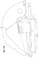
- FIGS. 12-14 illustrate the apparatus in use shearing a flat stock workpiece 54.
- Flat stock is most effectively sheared with at least one of the blade assemblies oriented at an angle relative to the other blade assembly. This provides a "scissors" cutting effect.
- the preferred angle depends upon the size and composition of the workpiece.
- the present apparatus permits the shear angle to be adjusted for cutting flat stock.
- the movable shear blade assembly is then adjusted so that it would have a -4.5° angle relative to the stationary blade assembly when about half of the flat stock 54 has been sheared (FIGS. 13 and 13A).
- the guide pin 132 is adjusted so that the second arm 84 pivots about its axis on the first arm 26 to orient the movable shear blade assembly to about a -5° angle when the shear blade assemblies are in the open position (i.e., with the movable shear blade assembly blades 81 and 82 at the top of the stroke as shown in FIGS. 12 and 12A).
- the movable shear blade assembly is at an angle of about -3.8° relative to the stationary shear blades 61, 62, and 63.
- the shearing angle varies less than about 1° from the desired shear angle between the initial contact of the movable shear blades with the flat stock and the point at which the movable blade edges pass beyond the bottom of the flat stock 54.
- the second arm 84 is initially oriented at a sufficient angle so that the edges of the movable blades 81 and 82 remain at an angle to the flat stock during the shearing stroke.
- the 90° angle outside corner of the movable shear blade 82 may be significantly displaced from the line 162 which bisects the 90° angle inside corner of the stationary shear blades 63 and 64.
- the line 163 extends upwardly from the 90° angle outside corner of the movable shear blade 82 through the second arm pivot axis and along the longitudinal axis of the slot 128.
- line 163 is skewed relative to, and crosses, the stationary blade inside corner bisecting line 162.
- line 164 is shown in a constant orientation perpendicular to the bisecting line 162 and passing through the pivot axis of the first arm 26.
- a modified, and preferred, form of the blade farm adjustment assembly is illustrated in the embodiment of the apparatus shown in FIGS. 15-18.
- the modified apparatus is designated generally by the reference numeral 20A in FIG. 15 and is substantially identical to the apparatus 20 described above with reference to FIGS. 1-14 except that the modified apparatus 20A has a second arm 84A with a modified upper end for cooperating with a modified adjustment assembly.
- the apparatus 20A includes a first arm 26A pivotally mounted with a bearing 28A to the frame having a front cover plate 22A and a rear cover plate 24A (FIGS. 16 and 18).
- the blade arm or second arm 84A is pivotally mounted with a shaft 108A to the first arm 26A in the same manner as the second arm 84 is mounted to the first arm 26 in the first embodiment described above with reference to FIGS. 1-14.
- the frame defines a workpiece receiving station having a stationary blade assembly comprising stationary shear blades 61A, 62A, 63A, and 64A.
- a movable shear blade assembly comprising shear blades 81A and 82A, is carried on the second arm 84A.
- a flat stock workpiece 54A is shown in the receiving station prior to being sheared.
- the stationary and movable shear blades of the apparatus 20A have substantially the same design, and operate in substantially the same way, as the shear blades of the apparatus 20 described above with reference to FIGS. 1-14.
- the upper end of the second arm 84A defines a slot 128A which functions as a guide way, and the slot is defined, in part, by a pair of spaced-apart guide surfaces or walls 128A' and 128A'' (FIG. 18).
- the walls 128A' and 128A'' each have an elongate straight portion, and the slot 128A defined between the wall straight portions is substantially elongate.
- the longitudinal axis of the elongate portion of the slot 128A passes through the second arm pivot axis and bisects the 90° angle outside corner of the movable shear blade assembly.
- the guide block 131A can move along the second arm slot 128A.
- the guide block 131A defines a generally cylindrical bore 136A (FIG. 18) for receiving a pin 132A.
- the guide block 131A receives the pin 132A in the bore 136A in a manner that permits the guide block 131A to rotate on the pin 132A in either direction of rotation.
- the pin 132A projects outwardly through an enlarged clearance slot 133A in the frame front cover plate 22A and through a bore 129A in an adjustment member or lever 134A.
- a retainer block 142A is welded to the front of the lever 134A.
- the retainer plate 142A defines a bore 143A (FIGS. 16 and 18) for receiving the pin 132A which projects therethrough and which is welded to the front surface of the retainer plate 142A.
- the adjustment lever 134A is pivotally mounted to the apparatus frame with a pivot pin 151A.
- the pin 151A is received in a cylindrical bore 153A in the frame rear cover plate 24A and is received in a cylindrical bore 155A in the frame front cover plate 22A.
- the pin 151A passes over the top of the first arm 26A as can be seen in FIG. 15.
- the pin 151A also passes through the end of the second arm slot 128A.
- the pin 151A extends outwardly through a bore 156A in the lever 134A.
- the outer end of the pin 151A extends through a bore 157A in the retainer plate 142A (FIGS. 16 and 18).
- the end of the pin 151A is welded to the retainer plate 142A which is, as explained above, welded to the front of the adjustment lever 134A.
- both pins 151A and 132A are fixed to the lever arm 134A.
- the pin 151A functions as a pivot shaft for the lever 134A intermediate first and second ends of the lever.
- the first end of the lever 134A at the left hand side of the machine as viewed in FIGS. 15-18, is adapted to be moved upwardly or downwardly to adjust the angle of the lever 134A relative to the frame.
- the lever 134A and the pivot pin 151A rotate together about the longitudinal pivot axis of the pin 151A.
- At the first end of the lever there is an adjustable latch assembly to secure the lever 134A in a selected one of a plurality of orientations relative to the frame.
- the front cover plate 22A of the frame defines a plurality of spaced-apart bores 171A.
- the bores 171A lie along a circular arc, the center of which is the longitudinal axis of the pin 151A.
- the first end of the lever 134A carries an adjustment latch assembly 173A (FIGS. 15-17).
- the assembly 173A includes a knob 175A connected with a cross pin 177A to a shaft 179A.
- the shaft 179A is received within a bushing 181A which is threadingly mounted in a threaded aperture 183A defined in the first end of the lever 134A.
- the bushing 181A defines a first bore 185A for receiving an outer portion of the shaft 179A and defines an enlarged bore 187A for receiving an inner portion of the shaft 179A and a helical, compression spring 189A which is disposed around the shaft 179A.
- the shaft 179A includes an enlarged distal end portion 191A which is adapted to enter into a selected one of the frame apertures 171A.
- the compression spring 189A is retained within the bore 187A by the enlarged portion 191A of the shaft 179A.
- the adjustment assembly knob 175A can be pulled outwardly, overcoming the biasing force of the spring 189A, to pull the shaft enlarged portion 191A out of the frame bore 171A.
- the lever 134A can then be pivoted to a new position, and the knob 175A can be released to permit the shaft enlarged portion 191A to be received in a new frame bore 171A so as to lock the lever 134A in the new orientation.
- the front surface of the frame front cover plate 22A can be provided with numbers or other indicia corresponding to a selected blade angle.
- the selected blade angle indicium is visible through an aperture 172A.
- the adjustment lever 134A is latched with the latch assembly 173A to maintain the pin 132A at the selected position. Subsequently, when the apparatus is operated to pivot the first arm 26A downwardly to shear a workpiece, the second arm 84A slides downwardly relative to the pin 132A and the guide block 131A. The guide block 131A remains retained within the slot 128A.
- the use of the lever 134A to select an initial orientation of the second arm 84A is effective in establishing a desired initial angle for the movable shear blades 81A and 82A. If the distance between the first arm pivot axis (defined by the bearing 28A) and the second arm pivot axis (defined by the shaft 108A) is great enough, the blade angle will not change very much during the shearing of the workpiece. Thus, a substantially optimum blade angle can be selected with this embodiment of the apparatus 20A for shearing operation of flat stock and/or angle iron in substantially the same manner as described above for the first embodiment of the apparatus 20 illustrated in FIGS. 1-14.
Landscapes
- Engineering & Computer Science (AREA)
- Mechanical Engineering (AREA)
- Shearing Machines (AREA)
Applications Claiming Priority (2)
| Application Number | Priority Date | Filing Date | Title |
|---|---|---|---|
| US08/073,123 US5394782A (en) | 1993-06-07 | 1993-06-07 | Shearing apparatus |
| US73123 | 1993-06-07 |
Publications (1)
| Publication Number | Publication Date |
|---|---|
| EP0630717A1 true EP0630717A1 (fr) | 1994-12-28 |
Family
ID=22111863
Family Applications (1)
| Application Number | Title | Priority Date | Filing Date |
|---|---|---|---|
| EP94108634A Withdrawn EP0630717A1 (fr) | 1993-06-07 | 1994-06-06 | Cisaille avec réglage de l'angle de la lame |
Country Status (2)
| Country | Link |
|---|---|
| US (1) | US5394782A (fr) |
| EP (1) | EP0630717A1 (fr) |
Cited By (4)
| Publication number | Priority date | Publication date | Assignee | Title |
|---|---|---|---|---|
| ES2206059A1 (es) * | 2002-10-28 | 2004-05-01 | Tariosan Xxi, S.L. | Sistema para cortar perfiles. |
| CN110315140A (zh) * | 2019-07-25 | 2019-10-11 | 马鞍山钢铁股份有限公司 | 一种型钢锯机角钢锯切的控制方法 |
| CN112518356A (zh) * | 2020-11-30 | 2021-03-19 | 上海骄成机电设备有限公司 | 一种极耳裁切装置 |
| CN114918991A (zh) * | 2022-07-19 | 2022-08-19 | 山东劳动职业技术学院(山东劳动技师学院) | 一种计算机主板加工用的剪切装置 |
Families Citing this family (3)
| Publication number | Priority date | Publication date | Assignee | Title |
|---|---|---|---|---|
| US7137328B1 (en) * | 2003-11-21 | 2006-11-21 | Tilton Richard H | Hydraulic press |
| US7418773B2 (en) | 2007-01-30 | 2008-09-02 | Peddinghaus Corporation | Punch and drill machine for a structural angle |
| US8021086B2 (en) * | 2007-03-28 | 2011-09-20 | Controlled Automation, Incorporated | Drilling apparatus and method |
Citations (3)
| Publication number | Priority date | Publication date | Assignee | Title |
|---|---|---|---|---|
| DE458678C (de) * | 1928-04-17 | Berlin Erfurter Maschinenfabri | Profileisen-Schneidmaschine mit aneinander vorbeischneidenden Messern | |
| DE7328336U (de) * | 1972-08-11 | 1973-12-06 | Tanaka I | Vorrichtung zum mechanischen Ab schneiden von Flanschen von profilierten Stahlbauteilen, wie H , I, U Profilen od dgl |
| US3866522A (en) * | 1973-07-27 | 1975-02-18 | Jr Harry L Oswalt | Metal working machine |
Family Cites Families (12)
| Publication number | Priority date | Publication date | Assignee | Title |
|---|---|---|---|---|
| US723599A (en) * | 1902-12-20 | 1903-03-24 | Ignaz Grimm | Combined split and bar-cutting power-shears. |
| US1259801A (en) * | 1916-11-03 | 1918-03-19 | Charles A Stich | Shearing and punching machine. |
| US3131589A (en) * | 1961-02-06 | 1964-05-05 | Cincinnati Shaper Co | Leveling and rake control for hydraulic shear |
| US3181407A (en) * | 1963-08-05 | 1965-05-04 | Pacific Ind Mfg Co | Shear machine with adjustable ram having means to immobilize said machine during adjustment |
| US3263541A (en) * | 1964-08-18 | 1966-08-02 | Wysong & Miles Company | Metal working machines |
| US3371569A (en) * | 1965-06-28 | 1968-03-05 | Pacific Press & Shear Corp | Shear machine or the like |
| US3701276A (en) * | 1970-07-15 | 1972-10-31 | Excel Mfg Ltd | Iron and metal working machinery |
| DE2525391C3 (de) * | 1975-06-06 | 1986-10-23 | Peddinghaus, Rolf, Dipl.-Ing., 5828 Ennepetal | Druckmittelbetätigte Schere, Lochstanze o.dgl. Maschine |
| AU552891B2 (en) * | 1981-05-26 | 1986-06-26 | Amada Company Limited | Sharing machine-adjustable stroke and clearance |
| US4660451A (en) * | 1985-09-20 | 1987-04-28 | Bjoerkheim Pekka | Scrap shearer |
| US4854201A (en) * | 1987-11-06 | 1989-08-08 | Topy Kogyo Kabushiki Kaisha | Valve hole punching apparatus for a wheel |
| US5170689A (en) * | 1991-05-20 | 1992-12-15 | Jim Dvorak | Metal working machine |
-
1993
- 1993-06-07 US US08/073,123 patent/US5394782A/en not_active Expired - Fee Related
-
1994
- 1994-06-06 EP EP94108634A patent/EP0630717A1/fr not_active Withdrawn
Patent Citations (3)
| Publication number | Priority date | Publication date | Assignee | Title |
|---|---|---|---|---|
| DE458678C (de) * | 1928-04-17 | Berlin Erfurter Maschinenfabri | Profileisen-Schneidmaschine mit aneinander vorbeischneidenden Messern | |
| DE7328336U (de) * | 1972-08-11 | 1973-12-06 | Tanaka I | Vorrichtung zum mechanischen Ab schneiden von Flanschen von profilierten Stahlbauteilen, wie H , I, U Profilen od dgl |
| US3866522A (en) * | 1973-07-27 | 1975-02-18 | Jr Harry L Oswalt | Metal working machine |
Cited By (7)
| Publication number | Priority date | Publication date | Assignee | Title |
|---|---|---|---|---|
| ES2206059A1 (es) * | 2002-10-28 | 2004-05-01 | Tariosan Xxi, S.L. | Sistema para cortar perfiles. |
| WO2004037474A1 (fr) * | 2002-10-28 | 2004-05-06 | Eisen Xxi, S.L. | Systeme permettant de decouper des profils |
| CN110315140A (zh) * | 2019-07-25 | 2019-10-11 | 马鞍山钢铁股份有限公司 | 一种型钢锯机角钢锯切的控制方法 |
| CN110315140B (zh) * | 2019-07-25 | 2020-11-27 | 马鞍山钢铁股份有限公司 | 一种型钢锯机角钢锯切的控制方法 |
| CN112518356A (zh) * | 2020-11-30 | 2021-03-19 | 上海骄成机电设备有限公司 | 一种极耳裁切装置 |
| CN114918991A (zh) * | 2022-07-19 | 2022-08-19 | 山东劳动职业技术学院(山东劳动技师学院) | 一种计算机主板加工用的剪切装置 |
| CN114918991B (zh) * | 2022-07-19 | 2022-11-04 | 山东劳动职业技术学院(山东劳动技师学院) | 一种计算机主板加工用的剪切装置 |
Also Published As
| Publication number | Publication date |
|---|---|
| US5394782A (en) | 1995-03-07 |
Similar Documents
| Publication | Publication Date | Title |
|---|---|---|
| US4974436A (en) | Cutting tool to facilitate bending of hollow tubing | |
| CA1180265A (fr) | Tondeuse | |
| US6520060B2 (en) | Cut-off mechanism for elongate stock | |
| US5394782A (en) | Shearing apparatus | |
| CA1274169A (fr) | Jeu de filieres coupe-tube | |
| CA2187144C (fr) | Systeme de positionnement d'outil motorise | |
| CN112170722B (zh) | 一种摆动式焊丝剪切装置 | |
| US4638703A (en) | Shear for different structural shapes | |
| US3918339A (en) | Rocking action shearing apparatus with a pivot axis for the movable blade inclined to the cutting edge of the stationary blade | |
| US6000268A (en) | Multifunction machine for modifying material in a bending brake | |
| US5170689A (en) | Metal working machine | |
| DE2624255B2 (de) | Schneidevorrichtung | |
| US20080289186A1 (en) | Scissor shear apparatus for shearing material | |
| US6993950B2 (en) | Rebar cutter and bender | |
| DE3233208C1 (de) | Ausklinkvorrichtung | |
| US4499803A (en) | Double cut die set with improved pull-across notching feature | |
| US4998349A (en) | Key-cutting device | |
| US4993297A (en) | Shearing blade mount for cut-off die set | |
| US4672835A (en) | Apparatus for bending sheet material | |
| DE69920763T2 (de) | Sägemaschine mit schwingbewegung | |
| US5408908A (en) | Cutting machine | |
| US7401539B2 (en) | Blade material cutting device | |
| US3996831A (en) | Metal shearing machine | |
| US6461232B1 (en) | Toe web cutter with stationary blade unit | |
| US3691890A (en) | Shearing machine |
Legal Events
| Date | Code | Title | Description |
|---|---|---|---|
| PUAI | Public reference made under article 153(3) epc to a published international application that has entered the european phase |
Free format text: ORIGINAL CODE: 0009012 |
|
| AK | Designated contracting states |
Kind code of ref document: A1 Designated state(s): DE ES GB IT |
|
| STAA | Information on the status of an ep patent application or granted ep patent |
Free format text: STATUS: THE APPLICATION IS DEEMED TO BE WITHDRAWN |
|
| 18D | Application deemed to be withdrawn |
Effective date: 19950629 |