EP0631216A2 - Procédé et circuit de contrôle pour régler la pression avec les vannes magnétiques par exemple pour contrôler la pression de tubulaires en matière plastique - Google Patents
Procédé et circuit de contrôle pour régler la pression avec les vannes magnétiques par exemple pour contrôler la pression de tubulaires en matière plastique Download PDFInfo
- Publication number
- EP0631216A2 EP0631216A2 EP94107603A EP94107603A EP0631216A2 EP 0631216 A2 EP0631216 A2 EP 0631216A2 EP 94107603 A EP94107603 A EP 94107603A EP 94107603 A EP94107603 A EP 94107603A EP 0631216 A2 EP0631216 A2 EP 0631216A2
- Authority
- EP
- European Patent Office
- Prior art keywords
- control
- pulse
- pressure
- solenoid valve
- solenoid valves
- Prior art date
- Legal status (The legal status is an assumption and is not a legal conclusion. Google has not performed a legal analysis and makes no representation as to the accuracy of the status listed.)
- Granted
Links
- 238000012360 testing method Methods 0.000 title claims abstract description 48
- 238000000034 method Methods 0.000 title claims description 14
- 239000004033 plastic Substances 0.000 title claims description 3
- 230000001105 regulatory effect Effects 0.000 title description 2
- 238000001208 nuclear magnetic resonance pulse sequence Methods 0.000 claims abstract description 13
- 230000001960 triggered effect Effects 0.000 claims abstract description 11
- 101001105816 Homo sapiens Vitamin K-dependent protein Z Proteins 0.000 claims description 12
- 102100021208 Vitamin K-dependent protein Z Human genes 0.000 claims description 12
- 238000011144 upstream manufacturing Methods 0.000 claims description 3
- 238000009530 blood pressure measurement Methods 0.000 claims description 2
- 230000005540 biological transmission Effects 0.000 claims 1
- 238000001514 detection method Methods 0.000 claims 1
- 230000000694 effects Effects 0.000 abstract description 4
- 230000000737 periodic effect Effects 0.000 abstract 1
- 238000010586 diagram Methods 0.000 description 5
- XLYOFNOQVPJJNP-UHFFFAOYSA-N water Substances O XLYOFNOQVPJJNP-UHFFFAOYSA-N 0.000 description 5
- 230000001276 controlling effect Effects 0.000 description 4
- JWBMZIJMSBFBIY-UHFFFAOYSA-N 1-(3-chloro-2,6-dihydroxy-4-methoxyphenyl)hexan-1-one Chemical compound CCCCCC(=O)C1=C(O)C=C(OC)C(Cl)=C1O JWBMZIJMSBFBIY-UHFFFAOYSA-N 0.000 description 2
- 101100420776 Arabidopsis thaliana SYN1 gene Proteins 0.000 description 2
- VUDQSRFCCHQIIU-UHFFFAOYSA-N DIF1 Natural products CCCCCC(=O)C1=C(O)C(Cl)=C(OC)C(Cl)=C1O VUDQSRFCCHQIIU-UHFFFAOYSA-N 0.000 description 2
- 101150001108 DIF1 gene Proteins 0.000 description 2
- 102100024409 Gametogenetin-binding protein 2 Human genes 0.000 description 2
- 101000833430 Homo sapiens Gametogenetin-binding protein 2 Proteins 0.000 description 2
- 230000032683 aging Effects 0.000 description 2
- 238000011161 development Methods 0.000 description 2
- 230000018109 developmental process Effects 0.000 description 2
- 230000004913 activation Effects 0.000 description 1
- 230000000903 blocking effect Effects 0.000 description 1
- 238000006243 chemical reaction Methods 0.000 description 1
- 230000001934 delay Effects 0.000 description 1
- 230000003111 delayed effect Effects 0.000 description 1
- 230000001419 dependent effect Effects 0.000 description 1
- 239000000463 material Substances 0.000 description 1
- 238000005259 measurement Methods 0.000 description 1
- 238000012544 monitoring process Methods 0.000 description 1
- 230000002265 prevention Effects 0.000 description 1
- 239000012815 thermoplastic material Substances 0.000 description 1
- 230000001052 transient effect Effects 0.000 description 1
- 238000013022 venting Methods 0.000 description 1
Images



Classifications
-
- G—PHYSICS
- G05—CONTROLLING; REGULATING
- G05D—SYSTEMS FOR CONTROLLING OR REGULATING NON-ELECTRIC VARIABLES
- G05D16/00—Control of fluid pressure
- G05D16/20—Control of fluid pressure characterised by the use of electric means
- G05D16/2006—Control of fluid pressure characterised by the use of electric means with direct action of electric energy on controlling means
- G05D16/2013—Control of fluid pressure characterised by the use of electric means with direct action of electric energy on controlling means using throttling means as controlling means
- G05D16/2026—Control of fluid pressure characterised by the use of electric means with direct action of electric energy on controlling means using throttling means as controlling means with a plurality of throttling means
- G05D16/2046—Control of fluid pressure characterised by the use of electric means with direct action of electric energy on controlling means using throttling means as controlling means with a plurality of throttling means the plurality of throttling means being arranged for the control of a single pressure from a plurality of converging pressures
- G05D16/2053—Control of fluid pressure characterised by the use of electric means with direct action of electric energy on controlling means using throttling means as controlling means with a plurality of throttling means the plurality of throttling means being arranged for the control of a single pressure from a plurality of converging pressures the plurality of throttling means comprising only a first throttling means acting on a higher pressure and a second throttling means acting on a lower pressure, e.g. the atmosphere
-
- G—PHYSICS
- G01—MEASURING; TESTING
- G01N—INVESTIGATING OR ANALYSING MATERIALS BY DETERMINING THEIR CHEMICAL OR PHYSICAL PROPERTIES
- G01N3/00—Investigating strength properties of solid materials by application of mechanical stress
- G01N3/08—Investigating strength properties of solid materials by application of mechanical stress by applying steady tensile or compressive forces
- G01N3/10—Investigating strength properties of solid materials by application of mechanical stress by applying steady tensile or compressive forces generated by pneumatic or hydraulic pressure
- G01N3/12—Pressure testing
-
- G—PHYSICS
- G01—MEASURING; TESTING
- G01N—INVESTIGATING OR ANALYSING MATERIALS BY DETERMINING THEIR CHEMICAL OR PHYSICAL PROPERTIES
- G01N2203/00—Investigating strength properties of solid materials by application of mechanical stress
- G01N2203/003—Generation of the force
- G01N2203/0042—Pneumatic or hydraulic means
- G01N2203/0048—Hydraulic means
-
- G—PHYSICS
- G01—MEASURING; TESTING
- G01N—INVESTIGATING OR ANALYSING MATERIALS BY DETERMINING THEIR CHEMICAL OR PHYSICAL PROPERTIES
- G01N2203/00—Investigating strength properties of solid materials by application of mechanical stress
- G01N2203/02—Details not specific for a particular testing method
- G01N2203/026—Specifications of the specimen
- G01N2203/0262—Shape of the specimen
- G01N2203/0274—Tubular or ring-shaped specimens
Definitions
- the invention relates to a method and a control circuit for pressure regulation in pressurized devices, e.g. for pressure testing of plastic pipes, according to the preamble of claim 1 or claim 8.
- the object of the invention is therefore to provide a method and a corresponding control circuit for pressure control by solenoid valves, with which it is possible to comply with the narrow tolerance limits set for the pressure test given the various boundary conditions in a test system.
- the invention takes into account the fact that the pull-in side of a solenoid valve is very much dependent on the pressure difference between the inlet and outlet of the valves.
- Tightening times are between 5 and 40 to 50 ms, for example.
- Uniformly long control pulses the duration of which must be longer than the longest possible tightening period, for example 100 ms, can therefore lead to very different valve opening times between, for example, 50 and 95 ms.
- the invention therefore takes a different path by starting from a respective first control pulse with a predetermined duration, e.g. 5 ms, if the deviation from the test pressure persists, the control pulses are repeated periodically, the duration of each subsequent control pulse being a predetermined time period, e.g. extended by 5 ms compared to the previous pulse.
- the solenoid valve finally pulls up in the course of the respective control pulse sequence for one of the control pulses, with the first opening control pulse remaining open for a maximum of 5 ms, for example, and the opening times being gradually increased with the subsequent control pulses.
- the pressure control by the individual solenoid valves can thus be metered in a simple manner with a suitable specification of the pulse extension time, since no calculations are necessary, but only the number of successive control pulses must be recorded.
- the associated extension of the standard time is irrelevant, however, since the test specimens generally only expand slowly.
- the structure of the solenoid valve control unit according to the invention results from the features of claim 8.
- the essential components are then a pulse stage for generating the control pulses with increasing pulse duration and a pulse counter for determining the respective pulse in a pulse train in conjunction with a down counter that can be preset thereby for determination the respective pulse duration.
- Further developments result from the further claims 9 to 12, which are in particular refer to an additional pause counter and to an additional switch for controlling the various solenoid valves
- test system shown in Figure 1 consists of several test stations ST1 to STn for testing pressure pipes made of thermoplastic materials for their life expectancy by artificially aging at elevated temperatures and / or elevated pressures. For safety reasons, this aging test is carried out with pressurized water. Accordingly, each of the test stations ST ... consists of a water supply bottle DWB filled with a test piece P connected via a solenoid valve MV4, both of which are filled with water from the water line W via the solenoid valve MV2. Then the water in the pressure supply bottle DWB and thus the test object P is pressurized with compressed gas via the compressed gas line DL and the solenoid valve MV1. Another solenoid valve MV3 is used to reduce the pressure if necessary.
- Pressure gauges M constantly monitor the prevailing test pressure and report it to the control device STE assigned to each test station ST ..., all of which are connected to a central control processor PROZ via a processor line system ST-BUS.
- This control processor controls the course of the test at the individual station ST in a manner known per se. For this purpose, the measured variables continuously determined by the individual control devices STE are transmitted to them so that they can be compared with the specified test parameters and in the event of deviations the necessary control commands can be issued, which are passed on by the control device STE concerned to the corresponding control devices.
- the individual test pressures at the individual test stations ST ... of a test system can be between 1 and 125 bar depending on the pipe material, the nominal pressure and the type of test. This requires a high supply pressure in the central supply network with the compressed gas line DL, which, depending on the test pressure to be set at the individual test stations, leads to different pressure differences P DIF1 and P DIF3 at the solenoid valves MV1 and MV3 and thus to very different tightening delays for the individual solenoid valves can lead.
- a separate solenoid valve control unit MVST is provided for the pressure regulating solenoid valves MV1 and MV3, which is acted upon by the respective control device STE with the control signals derived from the control commands of the central processor PROZ, as will be explained later.
- the solenoid valves MV1 react very differently depending on the pressure difference P DIF ... existing between the inlet and outlet, and the pressure increases associated with the opening of the solenoid valve MV1 are also different.
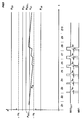
- P DIFy - solid line - in comparison to a much higher pressure difference P DIFx - dashed line - the solenoid valve MV1 reacts faster, namely after the tightening time t Ay compared to the longer tightening time t Ax with the higher pressure difference P DIFx .
- the pressure increase associated with the opening of the solenoid valve MV1 at a low pressure difference P DIFy is significantly lower and flatter in spite of the longer valve opening time in contrast to that at the higher pressure difference P DIFx .
- the MV3 solenoid valve for venting also reacts depending on the pressure difference P DIF ... with different effects on the test pressure, which is reduced at a lower pressure difference P DIFy and runs more flatly than at higher pressure differences P DIFx . Since P DIF1 is inversely proportional to P DIF3 , a slow pressure increase via the solenoid valve MV1 is usually associated with a strong pressure drop via the solenoid valve MV3.
- FIG. 3 shows the course of the pressure P M measured at one of the test stations ST ... of FIG. 1 over time t in a control according to the invention in a schematic representation, with P SET, the desired pressure to be maintained with the tolerance limits +1% and - 1% is shown.
- P U2 and P O2 continue to denote the switching thresholds, when falling below or exceeding the coarse control takes effect in accordance with continuous pulse operation and when they are exceeded or undershot until the next switching threshold P U1 or P O1 the fine control according to the pulse sequence operation according to the invention is carried out. However, there is no regulation between the two switching thresholds P U1 and P O1 .
- the switching threshold P U2 is calculated, based on the highest possible pressure difference in the system, in such a way that exceeding the tolerance limit is reliably avoided by a pressure increase triggered by the control pulses. The same applies to the downward regulation with regard to the switching threshold P02.
- each cycle Z ... lasts, for example, 100 ms, and in each cycle, every n stations ST1 STn are called once at the same time intervals to take over the respective measurement result P M provided by an analog / digital converter from the control computer PROZ and the corresponding control signals are determined .
- the measured value P M falls below the switching threshold P O1 in the cycle Z2, which is measured at the beginning of the cycle Z3 and causes the processor PROZ to activate the fine control effectively.
- the solenoid valve control unit emits the first control pulse MV1 OUT , which, however, has no effect because of the decisive response time t A1 .
- the extended control pulses MV1 OUT triggered in the subsequent cycles Z4 and Z5.
- the solenoid valve MV1 Only in cycle Z6 is the response time t A1 exceeded by the control pulse and the solenoid valve MV1 is opened for a short time for the first time, so that the test pressure P M rises slightly. Since too low a pressure is still measured at the beginning of cycle Z7, the control pulse sequence must be continued until a pressure P M above the switching threshold P U1 is measured at the beginning of cycle Z9. The pressure is increased gradually in fine doses.
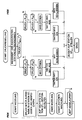
- FIG. 4 and FIG. 5 show the flow diagrams of the control programs running in the processor PROZ in this connection, FIG. 4 referring to an interruption routine called periodically for taking over the measured values from the individual stations STi and FIG. 5 to the pressure regulation routine in the main program of the controlling processor PROZ.
- the measured on the pressure gauge pressure P M M for the selected station STi is read and provided for the subsequent main program. Then the next station STi + 1 is switched to, which means that the end of this routine has been reached, so that it is possible to jump back to the main program and start the time monitoring for a new call of the interrupt routine.
- This interruption routine is run through n times in a test system n times in one of the cycles Z ... shown in FIG. 3, and all stations are activated at the same time intervals to record their measured values.
- the pressure control routine according to FIG. 5 is then called up, among other things, which reacts on the basis of the measured value available for a given station STi.
- a pointer to the next station STi + 1 is then set, so that the next station STi + 1 is checked when this routine is subsequently called up again.
- the commands "MV ... Open” or “MV ... Close” as well as “Clock MV ... On” or “Clock MV ... Off” transmitted by the processor PROZ to the respective station ST ... are issued by the Control unit STE in each case converted into a combination of three signals for solenoid valve control unit MVST, namely into an individual signal MV1 IN or MV3 IN for the selection of the solenoid valve MV1 or MV3 to be controlled in each case and into a signal TEA indicating the type of regulation together for both solenoid valves MV ....
- FIG. 6 shows the block diagram of the solenoid valve control unit MVST which processes these signals in connection with timing pulses CL.
- this solenoid valve control unit there is a turnout circuit consisting of an OR gate OR2 and, with AND gates U6 and U7, for individual control of one of the two solenoid valves MV1 or MV3 with the corresponding control pulses MV1 OUT or MV3 OUT .
- the selection is made directly by the control signals MV1 IN or MV3 IN , while the actual control pulses for the solenoid valves are supplied via the common OR gate OR2, namely either as a continuous pulse corresponding to the coarse control derived from the inverted control signal TEA or as a bistable flip-flop KS1 - a pulse level consisting of the two flip-flops KS1 and KS2 - delivered pulse sequence for fine control.
- the bistable flip-flop KS1 is set via the upstream AND gate U1 by the leading edge of a timing pulse CL when the second flip-flop KS2 is reset and no reset signal is effective via the AND gate U3.
- the control pulse thereby triggered at output Q releases the flip-flop KS3 via the inverted reset input R, which is subsequently set with the trailing edge of the controlling timing pulse CL via the AND gate U2.
- a pulse counter IZ which is reset and released by the inverted signal TEA, is switched through the OR gate OR1 by one step with each control pulse output by the flip-flop KS1.
- This counter is coupled to a reverse counter RZ, which can be loaded with the counter reading of the pulse counter IZ by setting the flip-flop KS3 and the downstream pulse shaper IG via the input L and can be reset step by step using the clock pulse CL.
- the pulse counter is set to the value 1 for the first pulse of the flip-flop KS1, to the value 2 for the second pulse, the duration of each control pulse supplied by the flip-flop KS1 is extended from pulse to pulse by the duration of one clock cycle period Clock pulses CL.
- the blocking time corresponding to the pause between the control pulses of the flip-flop KS1 can e.g. are predetermined by a periodically recurring time slice signal ZS, which coincides with the beginning of a cycle Z ... for a station ST ... from FIG.
- the pause duration can also be derived from a separate pause counter PZ, which is incremented by the timing pulses ZL and is released in each case when the flip-flop KS2 is set at the end of the control pulse triggered by the flip-flop KS1.
- PZ pause counter
- a 7-bit counter with a counting capacity of 128 there are, for example, intervals of 640 ms with a cycle period of 5 ms compared to a cycle time of e.g. 100ms.
Landscapes
- Physics & Mathematics (AREA)
- Fluid Mechanics (AREA)
- General Physics & Mathematics (AREA)
- Engineering & Computer Science (AREA)
- Automation & Control Theory (AREA)
- Health & Medical Sciences (AREA)
- Life Sciences & Earth Sciences (AREA)
- Chemical & Material Sciences (AREA)
- Analytical Chemistry (AREA)
- Biochemistry (AREA)
- General Health & Medical Sciences (AREA)
- Immunology (AREA)
- Pathology (AREA)
- Control Of Fluid Pressure (AREA)
- Measuring Fluid Pressure (AREA)
Applications Claiming Priority (2)
| Application Number | Priority Date | Filing Date | Title |
|---|---|---|---|
| DE4316560A DE4316560C2 (de) | 1993-05-18 | 1993-05-18 | Verfahren zur Druckregelung durch Magnetventile an unter Druck stehenden Einrichtungen, z.B. an Einrichtungen zur Druckprüfung bei Kunststoffrohren, sowie Steuerschaltung für Magnetventile |
| DE4316560 | 1993-05-18 |
Publications (3)
| Publication Number | Publication Date |
|---|---|
| EP0631216A2 true EP0631216A2 (fr) | 1994-12-28 |
| EP0631216A3 EP0631216A3 (fr) | 1995-02-01 |
| EP0631216B1 EP0631216B1 (fr) | 2000-04-05 |
Family
ID=6488349
Family Applications (1)
| Application Number | Title | Priority Date | Filing Date |
|---|---|---|---|
| EP94107603A Expired - Lifetime EP0631216B1 (fr) | 1993-05-18 | 1994-05-17 | Procédé et circuit de contrôle pour régler la pression avec les vannes magnétiques par exemple pour contrôler la pression de tubulaires en matière plastique |
Country Status (3)
| Country | Link |
|---|---|
| EP (1) | EP0631216B1 (fr) |
| AT (1) | ATE191571T1 (fr) |
| DE (1) | DE4316560C2 (fr) |
Cited By (1)
| Publication number | Priority date | Publication date | Assignee | Title |
|---|---|---|---|---|
| CN106644547A (zh) * | 2017-01-03 | 2017-05-10 | 无锡塔尔基热交换器科技有限公司 | 脉冲模拟装置 |
Families Citing this family (4)
| Publication number | Priority date | Publication date | Assignee | Title |
|---|---|---|---|---|
| DE10012405A1 (de) * | 2000-03-15 | 2001-09-20 | Mannesmann Rexroth Ag | Einrichtung zur Steuerung eines hydraulischen Aktuators |
| DE102017113756B4 (de) | 2017-06-21 | 2022-01-27 | Poppe+Potthoff Maschinenbau GmbH | Verfahren und Vorrichtung zur Druckprüfung von beliebigen Prüflingen, deren Volumen mit einer Flüssigkeit gefüllt wird |
| DE102023107494B4 (de) | 2022-12-30 | 2024-08-22 | Poppe + Potthoff Maschinenbau GmbH | Verfahren zur Druckprüfung von beliebigen Prüflingen |
| EP4430373B1 (fr) | 2022-12-30 | 2026-03-25 | Poppe + Potthoff Maschinenbau Gmbh | Procédé de test de la pression de tout objet à tester |
Family Cites Families (5)
| Publication number | Priority date | Publication date | Assignee | Title |
|---|---|---|---|---|
| DE3502276A1 (de) * | 1985-01-24 | 1986-07-24 | Wabco Westinghouse Fahrzeugbremsen GmbH, 3000 Hannover | Einrichtung zur stetigen steuerung eines normalerweise fuer unstetige betriebsweise ausgebildeten magnetventiles |
| JPH0668282B2 (ja) * | 1986-04-18 | 1994-08-31 | 三菱自動車工業株式会社 | 圧力応動式アクチュエータの制御装置 |
| US4766921A (en) * | 1986-10-17 | 1988-08-30 | Moog Inc. | Method of operating a PWM solenoid valve |
| JPH02280206A (ja) * | 1989-04-21 | 1990-11-16 | Eishin Giken:Kk | 圧力設定器 |
| US4974622A (en) * | 1990-01-23 | 1990-12-04 | Borg-Warner Automotive, Inc. | Self compensation for duty cycle control |
-
1993
- 1993-05-18 DE DE4316560A patent/DE4316560C2/de not_active Expired - Fee Related
-
1994
- 1994-05-17 AT AT94107603T patent/ATE191571T1/de not_active IP Right Cessation
- 1994-05-17 EP EP94107603A patent/EP0631216B1/fr not_active Expired - Lifetime
Cited By (2)
| Publication number | Priority date | Publication date | Assignee | Title |
|---|---|---|---|---|
| CN106644547A (zh) * | 2017-01-03 | 2017-05-10 | 无锡塔尔基热交换器科技有限公司 | 脉冲模拟装置 |
| CN106644547B (zh) * | 2017-01-03 | 2024-05-17 | 无锡塔尔基热交换器科技有限公司 | 脉冲模拟装置 |
Also Published As
| Publication number | Publication date |
|---|---|
| DE4316560A1 (de) | 1994-11-24 |
| EP0631216A3 (fr) | 1995-02-01 |
| ATE191571T1 (de) | 2000-04-15 |
| EP0631216B1 (fr) | 2000-04-05 |
| DE4316560C2 (de) | 1996-11-07 |
Similar Documents
| Publication | Publication Date | Title |
|---|---|---|
| DE2803675A1 (de) | Verfahren und vorrichtung zum kontrollierten festziehen von schraubverbindungselementen | |
| DE3715591C2 (fr) | ||
| DE3789268T2 (de) | Vorrichtung zur Unterbrechung eines Gasflusses. | |
| DE2555005C2 (fr) | ||
| DE3633113A1 (de) | Verfahren und vorrichtung zur automatischen erfassung der ansprechspannung eines elektromagnetischen bauteils, insbesondere eines magnetventils | |
| DE2532817A1 (de) | Elektronische brennstoffsteuereinrichtung | |
| DE4136415A1 (de) | Verfahren und vorrichtung zum pruefen des betriebs eiens solenoids | |
| WO2022218553A1 (fr) | Procédé de détection d'une défaillance dans un relais | |
| EP0617262B1 (fr) | Suppression de l'interférence dans un dosimètre à taux d'allégement avec réglage de fuzzy | |
| EP0631216B1 (fr) | Procédé et circuit de contrôle pour régler la pression avec les vannes magnétiques par exemple pour contrôler la pression de tubulaires en matière plastique | |
| DE4215682A1 (de) | Verfahren und vorrichtung zur korrektur des reguliereinsatzpunktes und der regulierintensitaet | |
| EP0066682B1 (fr) | Dispositif de positionnement | |
| EP2609301B1 (fr) | Procédé de règlage d'une turbogénérateur | |
| DE2243742A1 (de) | Geraet zur digitalen steuerung der groesse des bearbeitungsspaltes bei einem funkenerosionsbearbeitungsprozess | |
| EP0046317B1 (fr) | Procédé et dispositif pour détecter la direction d'un court-circuit | |
| EP1075696B1 (fr) | Procede et dispositif pour surveiller la montee en puissance lors du demarrage d'un reacteur nucleaire (surveillance d'excursion diversitaire) | |
| DE102021118552B3 (de) | Verfahren und Vorrichtungen zum Erkennen von ausgangsseitigen Leckagen bei einem Doppelkegel-Luftleistungsverstärker | |
| EP3521841A1 (fr) | Procédé de déclenchement d'un relais de protection de distance surveillant une zone | |
| DE19619629C1 (de) | Verfahren und Anordnung zur automatischen Überwachung von Fehlerstromschutzschaltern | |
| DE10229905B4 (de) | Verfahren und Vorrichtung zum Erfassen des Einschwingzeitpunkts eines Reglers | |
| DE19717871C2 (de) | Verfahren zur Steuerung von Turbinensystemen in Wasserkraftwerken | |
| DE3419752C2 (fr) | ||
| DE2836508C3 (de) | Verfahren zur Steuerung eines Druckregulierungssystems bei an einem bzw. gleichzeitig an mehreren Prüflingen, insbesondere Konststoffrohrabschnitten, erfolgenden Dauerbelastungsprüfungen | |
| DE69808458T2 (de) | Elektronisches steuergerät zur unterscheiding zwischen falschen kontakten und zeitweiligen kontakten in einer kettenfadenwächtervorrichtung für webmaschinen | |
| DE2920735C2 (fr) |
Legal Events
| Date | Code | Title | Description |
|---|---|---|---|
| PUAI | Public reference made under article 153(3) epc to a published international application that has entered the european phase |
Free format text: ORIGINAL CODE: 0009012 |
|
| PUAL | Search report despatched |
Free format text: ORIGINAL CODE: 0009013 |
|
| AK | Designated contracting states |
Kind code of ref document: A2 Designated state(s): AT BE GB IT NL |
|
| AK | Designated contracting states |
Kind code of ref document: A3 Designated state(s): AT BE GB IT NL |
|
| 17P | Request for examination filed |
Effective date: 19950721 |
|
| 17Q | First examination report despatched |
Effective date: 19970422 |
|
| GRAG | Despatch of communication of intention to grant |
Free format text: ORIGINAL CODE: EPIDOS AGRA |
|
| GRAG | Despatch of communication of intention to grant |
Free format text: ORIGINAL CODE: EPIDOS AGRA |
|
| GRAH | Despatch of communication of intention to grant a patent |
Free format text: ORIGINAL CODE: EPIDOS IGRA |
|
| GRAH | Despatch of communication of intention to grant a patent |
Free format text: ORIGINAL CODE: EPIDOS IGRA |
|
| GRAA | (expected) grant |
Free format text: ORIGINAL CODE: 0009210 |
|
| AK | Designated contracting states |
Kind code of ref document: B1 Designated state(s): AT BE GB IT NL |
|
| REF | Corresponds to: |
Ref document number: 191571 Country of ref document: AT Date of ref document: 20000415 Kind code of ref document: T |
|
| GBT | Gb: translation of ep patent filed (gb section 77(6)(a)/1977) |
Effective date: 20000516 |
|
| ITF | It: translation for a ep patent filed | ||
| EN | Fr: translation not filed | ||
| PLBE | No opposition filed within time limit |
Free format text: ORIGINAL CODE: 0009261 |
|
| STAA | Information on the status of an ep patent application or granted ep patent |
Free format text: STATUS: NO OPPOSITION FILED WITHIN TIME LIMIT |
|
| 26N | No opposition filed | ||
| PGFP | Annual fee paid to national office [announced via postgrant information from national office to epo] |
Ref country code: GB Payment date: 20010502 Year of fee payment: 8 |
|
| PGFP | Annual fee paid to national office [announced via postgrant information from national office to epo] |
Ref country code: BE Payment date: 20010518 Year of fee payment: 8 |
|
| PGFP | Annual fee paid to national office [announced via postgrant information from national office to epo] |
Ref country code: AT Payment date: 20010521 Year of fee payment: 8 |
|
| PGFP | Annual fee paid to national office [announced via postgrant information from national office to epo] |
Ref country code: NL Payment date: 20010531 Year of fee payment: 8 |
|
| REG | Reference to a national code |
Ref country code: GB Ref legal event code: IF02 |
|
| PG25 | Lapsed in a contracting state [announced via postgrant information from national office to epo] |
Ref country code: GB Free format text: LAPSE BECAUSE OF NON-PAYMENT OF DUE FEES Effective date: 20020517 Ref country code: AT Free format text: LAPSE BECAUSE OF NON-PAYMENT OF DUE FEES Effective date: 20020517 |
|
| PG25 | Lapsed in a contracting state [announced via postgrant information from national office to epo] |
Ref country code: BE Free format text: LAPSE BECAUSE OF NON-PAYMENT OF DUE FEES Effective date: 20020531 |
|
| PG25 | Lapsed in a contracting state [announced via postgrant information from national office to epo] |
Ref country code: NL Free format text: LAPSE BECAUSE OF NON-PAYMENT OF DUE FEES Effective date: 20021201 |
|
| GBPC | Gb: european patent ceased through non-payment of renewal fee |
Effective date: 20020517 |
|
| NLV4 | Nl: lapsed or anulled due to non-payment of the annual fee |
Effective date: 20021201 |
|
| PG25 | Lapsed in a contracting state [announced via postgrant information from national office to epo] |
Ref country code: IT Free format text: LAPSE BECAUSE OF NON-PAYMENT OF DUE FEES Effective date: 20050517 |