EP0631367B1 - Moto-réducteur intégré avec train d'engrenage sans jeu - Google Patents
Moto-réducteur intégré avec train d'engrenage sans jeu Download PDFInfo
- Publication number
- EP0631367B1 EP0631367B1 EP94304243A EP94304243A EP0631367B1 EP 0631367 B1 EP0631367 B1 EP 0631367B1 EP 94304243 A EP94304243 A EP 94304243A EP 94304243 A EP94304243 A EP 94304243A EP 0631367 B1 EP0631367 B1 EP 0631367B1
- Authority
- EP
- European Patent Office
- Prior art keywords
- motor
- gearhead
- output
- motors
- coupled
- Prior art date
- Legal status (The legal status is an assumption and is not a legal conclusion. Google has not performed a legal analysis and makes no representation as to the accuracy of the status listed.)
- Expired - Lifetime
Links
- 230000000712 assembly Effects 0.000 claims abstract description 20
- 238000000429 assembly Methods 0.000 claims abstract description 20
- 238000009420 retrofitting Methods 0.000 abstract description 2
- 238000007493 shaping process Methods 0.000 description 8
- 239000003990 capacitor Substances 0.000 description 1
- 230000009977 dual effect Effects 0.000 description 1
- 239000002184 metal Substances 0.000 description 1
- 238000000034 method Methods 0.000 description 1
- 238000012986 modification Methods 0.000 description 1
- 230000004048 modification Effects 0.000 description 1
Images

Classifications
-
- H—ELECTRICITY
- H02—GENERATION; CONVERSION OR DISTRIBUTION OF ELECTRIC POWER
- H02P—CONTROL OR REGULATION OF ELECTRIC MOTORS, ELECTRIC GENERATORS OR DYNAMO-ELECTRIC CONVERTERS; CONTROLLING TRANSFORMERS, REACTORS OR CHOKE COILS
- H02P6/00—Arrangements for controlling synchronous motors or other dynamo-electric motors using electronic commutation dependent on the rotor position; Electronic commutators therefor
- H02P6/06—Arrangements for speed regulation of a single motor wherein the motor speed is measured and compared with a given physical value so as to adjust the motor speed
-
- F—MECHANICAL ENGINEERING; LIGHTING; HEATING; WEAPONS; BLASTING
- F16—ENGINEERING ELEMENTS AND UNITS; GENERAL MEASURES FOR PRODUCING AND MAINTAINING EFFECTIVE FUNCTIONING OF MACHINES OR INSTALLATIONS; THERMAL INSULATION IN GENERAL
- F16H—GEARING
- F16H57/00—General details of gearing
- F16H57/12—Arrangements for adjusting or for taking-up backlash not provided for elsewhere
-
- H—ELECTRICITY
- H01—ELECTRIC ELEMENTS
- H01Q—ANTENNAS, i.e. RADIO AERIALS
- H01Q3/00—Arrangements for changing or varying the orientation or the shape of the directional pattern of the waves radiated from an antenna or antenna system
- H01Q3/02—Arrangements for changing or varying the orientation or the shape of the directional pattern of the waves radiated from an antenna or antenna system using mechanical movement of antenna or antenna system as a whole
-
- H—ELECTRICITY
- H02—GENERATION; CONVERSION OR DISTRIBUTION OF ELECTRIC POWER
- H02K—DYNAMO-ELECTRIC MACHINES
- H02K7/00—Arrangements for handling mechanical energy structurally associated with dynamo-electric machines, e.g. structural association with mechanical driving motors or auxiliary dynamo-electric machines
- H02K7/10—Structural association with clutches, brakes, gears, pulleys or mechanical starters
- H02K7/116—Structural association with clutches, brakes, gears, pulleys or mechanical starters with gears
- H02K7/1163—Structural association with clutches, brakes, gears, pulleys or mechanical starters with gears where at least two gears have non-parallel axes without having orbital motion
-
- H—ELECTRICITY
- H02—GENERATION; CONVERSION OR DISTRIBUTION OF ELECTRIC POWER
- H02P—CONTROL OR REGULATION OF ELECTRIC MOTORS, ELECTRIC GENERATORS OR DYNAMO-ELECTRIC CONVERTERS; CONTROLLING TRANSFORMERS, REACTORS OR CHOKE COILS
- H02P1/00—Arrangements for starting electric motors or dynamo-electric converters
-
- H—ELECTRICITY
- H02—GENERATION; CONVERSION OR DISTRIBUTION OF ELECTRIC POWER
- H02P—CONTROL OR REGULATION OF ELECTRIC MOTORS, ELECTRIC GENERATORS OR DYNAMO-ELECTRIC CONVERTERS; CONTROLLING TRANSFORMERS, REACTORS OR CHOKE COILS
- H02P5/00—Arrangements specially adapted for regulating or controlling the speed or torque of two or more electric motors
- H02P5/68—Arrangements specially adapted for regulating or controlling the speed or torque of two or more electric motors controlling two or more DC dynamo-electric motors
- H02P5/69—Arrangements specially adapted for regulating or controlling the speed or torque of two or more electric motors controlling two or more DC dynamo-electric motors mechanically coupled by gearing
-
- F—MECHANICAL ENGINEERING; LIGHTING; HEATING; WEAPONS; BLASTING
- F16—ENGINEERING ELEMENTS AND UNITS; GENERAL MEASURES FOR PRODUCING AND MAINTAINING EFFECTIVE FUNCTIONING OF MACHINES OR INSTALLATIONS; THERMAL INSULATION IN GENERAL
- F16H—GEARING
- F16H57/00—General details of gearing
- F16H57/12—Arrangements for adjusting or for taking-up backlash not provided for elsewhere
- F16H2057/121—Arrangements for adjusting or for taking-up backlash not provided for elsewhere using parallel torque paths and means to twist the two path against each other
- F16H2057/122—Arrangements for adjusting or for taking-up backlash not provided for elsewhere using parallel torque paths and means to twist the two path against each other by using two independent drive sources, e.g. electric motors
-
- G—PHYSICS
- G05—CONTROLLING; REGULATING
- G05B—CONTROL OR REGULATING SYSTEMS IN GENERAL; FUNCTIONAL ELEMENTS OF SUCH SYSTEMS; MONITORING OR TESTING ARRANGEMENTS FOR SUCH SYSTEMS OR ELEMENTS
- G05B2219/00—Program-control systems
- G05B2219/30—Nc systems
- G05B2219/41—Servomotor, servo controller till figures
- G05B2219/41034—Two motors driven in opposite direction to take up backlash
Definitions
- the present invention relates generally to motors, and more particularly, to an integrated gearhead motor assembly incorporating two motors and two gearhead assemblies that provides for relatively high torque output with minimal backlash for use in precision servo systems.
- hydraulically controlled drive systems have been employed to provide for a drive system that produces a large amount of torque.
- Such drive systems are used in antenna control systems, for example.
- the hydraulic drive systems inherently produce little or no backlash, and are therefore very accurate when used to control the pointing of an antenna.
- conventional hydraulic drive systems are prone to leakage which is a definite drawback.
- a backlash-free drive having two coaxial wave drives is disclosed in SU-A-727 919.
- an integrated gearhead motor system that produces relatively high torque output with minimal backlash.
- the system may incorporate AC or DC electric motors or air motors, for example.
- the system uses two axially mounted electric motor and gearhead assemblies.
- the two motor and gearhead assemblies are connected to concentric output drive shafts, and each output shaft mates to a respective one of the gears of a split gear assembly.
- the split gear assembly is coupled to a gear of the drive shaft of a device that is to be driven by the integrated gearhead motor assembly.
- a tachometer is coupled between the first motor and a controller that is used to control the respective torques provided by the two motors.
- the split gear assembly By modulating the relative amount of torque provided by the two motors, the split gear assembly removes the backlash from the gearhead assemblies and gear interfaces to the drive shaft of the device that is to be driven.
- the system does this as an integrated assembly, and is adapted to replace a conventional single gearhead motor or hydraulic motor assembly.
- a second embodiment replaces the electric motors with air motors.
- the gearhead motor system may form part of a drive system for driving an output device.
- the drive system comprises first and second motors having first and second output shafts, respectively.
- a first gearhead assembly is coupled to the first output shaft of the first motor and has a first output drive shaft.
- a second gearhead assembly is coupled to the second output shaft of the second motor and comprises a second output drive shaft that is concentric with the first output drive shaft of the first gearhead assembly.
- a split gear assembly having first and second gear portions is coupled to respective output drive shafts of the first and second gearhead assemblies. The first and second gear portions are coupled by way of a drive gear to the output device.
- the drive system may further comprise a position sensor coupled to the drive gear for providing a position output signal indicative of the relative angular position of the drive gear and that is used to control the amount of torque provided by the drive system.
- a tachometer is coupled to a selected motor that is adapted to provide an angular rate output signal that is used to control the amount of torque provided by the drive system.
- Control circuitry is coupled to the tachometer, to the position sensor, and to each of the motors for controlling the amount of torque provided by the drive system to the output device in response to the position and rate output signals.
- the drive system thus provides for a single integrated assembly that is adapted to eliminate gear train backlash.
- the motor system incorporates the two motors and two gearhead assemblies into a single assembly, reducing weight and space requirements.
- the design also permits retrofitting of the dual motor and gearhead motor assembly into existing single motor drive systems. Conventional anti-backlash systems that use torquer motors cannot provide the output torque of the present gearhead motor assembly.
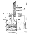
- Fig. 1 shows a cutaway side view of a drive system 10 comprising an integrated gearhead motor assembly 11 in accordance with the principles of the present invention.
- the integrated gearhead motor assembly 11 incorporates two motors and two gearhead assemblies to minimizes backlash produced by the system 10.
- the integrated gearhead motor assembly 11 is comprised of a housing 24, which may be comprised of metal or plastic, or the like.
- the first gearhead assembly 13 may be comprised of a model 3439129 gearhead assembly, manufactured by MPC, for example.
- the first gearhead assembly 13 has a first output shaft 18 that projects from an opening 25 in the housing 24.
- the first output shaft 18 of the first gearhead assembly 13 has a first diameter, which may be 9,52 mm (0.375 inches), for example.
- the first motor 12 may alternatively be comprised of an air motor.
- a second motor 14, which may be comprised of an electric motor, for example, and which is unique to the present invention, is coupled to a second gearhead assembly 15 by way of a second output shaft 17.
- the second motor 14 may alternatively be comprised of an air motor.
- the second gearhead assembly 15 is also unique to the present invention and is adapted to mate with the second motor 14 and cooperate with the first motor 13 and its output shaft 18.
- the uniqueness of the second motor 14 relates to an opening 26 in its center that permits the first output shaft 18 of the first motor 12 to project therethrough, and its output shaft 17.
- the uniqueness of the second gearhead assembly 15 relates to an opening 28 in its center that permits the first and second output shafts 17, 18 to project therethrough.
- the second gearhead assembly 15 has a second output shaft 19 that also projects from the opening 25 in the housing 24.
- the second output shaft 19 of the second gearhead assembly 15 is formed in the shape of a tube having an inner diameter through which the first output shaft 18 extends.
- the second output shaft 19 of the second gearhead assembly 15 has an inner diameter that is larger than the outer diameter of the first output shaft 18 first gearhead assembly 13, and which may be 9,83 mm (0.387 inches), for example.
- the output diameter of the output shaft of the second gearhead assembly 15 may be 19 mm (0.75 inches), for example.
- the first and second output shafts 18, 19 of the gearhead assemblies 13, 15 are free to rotate without interference with each other.
- the second motor 14 is also separated from the first gearhead assembly 13 and has the opening 26 in the center thereof through which the first output shaft 18 of the first gearhead assembly 13 projects.
- the two output shafts 18, 19 of the first and second gearhead assemblies 13, 15 are concentrically arranged and each output shaft 18, 19 mates to a respective gear 21, 22 of a split gear assembly 20.
- the split gear assembly 20 is coupled to a drive gear 29 of a drive shaft 27 of an output device 30 that is to be driven by the integrated gearhead motor assembly 11 or drive system 10.
- a tachometer 23 is disposed at one end of the housing 24 and is coupled to the first motor 12.
- the tachometer 23 may be comprised of a tachometer used on the model 3439129 motor, manufactured by MPC, for example.
- the tachometer 23 is also coupled by way of a controller 31 to internal control circuits of each of the motors 12, 14 and is adapted to control the amount of torque produced thereby that is coupled to the output device 30.
- Fig. 2 shows control circuitry comprising the controller 31 that is employed in the drive system 10 of Fig. 1.
- the controller 31 is coupled between the tachometer 23 and internal control circuits of the motors 12, 14.
- the controller 31 is comprised of an AC power source 33 that is coupled to each of the motors 12, 14.
- a position decoder 32 is coupled by way of an optional first phase sensitive detector 34 to a shaping amplifier circuit 35.
- the shaping amplifier circuit 35 is comprised of a shaping amplifier 36, and first and second filters 37, 38 that each comprise a resistor and a capacitor.
- the output of the shaping amplifier 36 is coupled to one input of a summing amplifier 41, whose output is coupled by way of a first control amplifier 42 to the internal control circuits of the first motor 12.
- the second input of the summing amplifier 41 is coupled to receive a torque bias input signal derived from a torque bias voltage source 46.
- the torque bias input signal is a fixed voltage that generates a desired torque difference between the output shafts 18, 19 of the first and second motors 12, 14.
- the output of the shaping amplifier 36 is also coupled by way of a second control amplifier 43 to the internal control circuits of the second motor 14.
- the tachometer 23 is coupled by way of an optional second phase sensitive detector 44 and a third filter circuit 45 to the input of the shaping amplifier circuit 35.
- the controller 31 and system 10 operates as follows and will be described with reference to Fig. 2.
- the first and second motors 13, 14 are powered by an AC voltage provided by the AC power source 33. Control voltages provided to each motor are independent of each other.
- a position transducer or sensor 32 such as an encoder or resolver, for example, provides position data from each of the first and second motors 13, 14.
- the tachometer 23 is utilized to provide rate data from each of the first and second motors 13, 14, by way of its respective motor shaft 18, 19. The position and rate data are combined using power techniques to compensate the overall servo loop for stable operation. This is accomplished by the shaping amplifier 36 and its associated components.
- the shaping amplifier output is routed to two independent outputs.
- the control amplifier for the second motor 14 has a conventional servo design, but the output for the first motor 13 has an additional summing amplifier that provides a desired level of anti-backlash torque.
- the anti-backlash torque may have either polarity, since it is always opposed by the torque from the second motor 14.
- the first and second motors 13, 14 turn at the same rate at all times since they are locked together by the split gear assembly 20 that is coupled to the drive gear 28 and output drive shaft 27 of the system 10.
- the drive system 10 of the present invention thus uses two axially mounted motors 12, 14 and gearhead assemblies 13, 15.
- the two motors 13, 15 and gearhead assemblies 12, 14 are mounted on concentric shafts 18, 19, and each shaft 18, 19 mates to the split gear assembly 20.
- the split gear assembly 20 is coupled to the drive shaft 27 of the device 30 that is to be driven.
- the tachometer 23 is coupled to the drive shaft 16 of the first motor 12 in order to derive rate data therefrom.
- the split gear assembly 20 By controlling the torque provided by each of the two motors 12, 14, the split gear assembly 20 removes the backlash produced by the gearhead assemblies 13, 15 and interfaces between gears 21, 22 and the drive gear 29 and drive shaft 27 of the device 30 that is to be driven.
- the present invention does this as an integrated assembly 11, and is adapted to replace a conventional single gearhead motor, such as the MPC model 3439129 motor, for example.
Landscapes
- Engineering & Computer Science (AREA)
- Power Engineering (AREA)
- General Engineering & Computer Science (AREA)
- Mechanical Engineering (AREA)
- Connection Of Motors, Electrical Generators, Mechanical Devices, And The Like (AREA)
- Gear Transmission (AREA)
- Control Of Motors That Do Not Use Commutators (AREA)
- Control Of Multiple Motors (AREA)
- Electric Propulsion And Braking For Vehicles (AREA)
Claims (9)
- Système moto-réducteur (11) pour l'entraînement d'un dispositif de sortie (30), ledit système moto-réducteur (11) comprenant:un premier moteur (12) ayant un premier arbre de sortie (16);un premier ensemble réducteur (13) couplé au premier arbre de sortie (16) du premier moteur (12), et qui comprend un premier arbre d'entraînement de sortie (18);un second moteur (14) ayant un second arbre de sortie (17);un second ensemble réducteur (15) couplé au second arbre de sortie (17) du second moteur (14), et qui comprend un second arbre d'entraînement de sortie (19), qui est concentrique par rapport au premier arbre d'entraînement de sortie (18) du premier ensemble réducteur (13); etun ensemble d'engrenages en deux parties (20) comprenant des première (21) et seconde (22) parties d'engrenages couplées aux arbres de sortie correspondants (18, 19) des premier et second ensembles réducteurs (13, 15), et dont les première (21) et seconde (22) parties d'engrenages sont couplées, par l'intermédiaire d'une roue dentée d'entraînement (29), au dispositif de sortie.
- Système moto-réducteur selon la revendication 1, comprenant en outre:
un tachymètre (23) couplé à un moteur sélectionné (12), qui est conçu pour produire un signal de sortie de vitesse angulaire, qui est utilisé pour régler le couple fourni par le système moto-réducteur (11). - Système moto-réducteur selon la revendication 1 ou la revendication 2, comprenant en outre:
un capteur de position (32) couplé à la roue dentée d'entraînement (29), pour produire un signal de sortie de position indiquant la position angulaire relative de la roue dentée d'entraînement (29), et qui est utilisé pour régler le couple fourni par le système moto-réducteur. - Système moto-réducteur selon la revendication 3, comprenant en outre:
un circuit de commande (31) couplé au tachymètre (23), au capteur de position (32), et à chacun des moteurs (12, 14), le circuit de commande (31) réglant le couple appliqué par le système moto-réducteur au dispositif de sortie (30) en réponse aux signaux de sortie de position et de vitesse angulaire. - Système d'entraînement (10) comprenant:un carter (24); etun système moto-réducteur (11) selon l'une quelconque des revendications précédentes, dans lequel le premier arbre d'entraînement de sortie (18) se projette depuis une ouverture (25) ménagée dans le carter (24), et le second arbre d'entraînement de sortie (19) se projette depuis l'ouverture ménagée dans le carter (24), le second arbre d'entraînement de sortie (19) étant concentrique par rapport au premier arbre d'entraînement de sortie (18).
- Système selon l'une quelconque des revendications précédentes, dans lequel les premier (12) et second (14) moteurs sont constitués de moteurs électriques.
- Système selon la revendication 6, dans lequel les premier (12) et second (14) moteurs sont constitués de moteurs électriques à courant alternatif.
- Système selon la revendication 6, dans lequel les premier (12) et second (14) moteurs sont constitués de moteurs électriques à courant continu.
- Système selon l'une quelconque des revendications précédentes, dans lequel les premier (12) et second (14) moteurs sont constitués de moteurs pneumatiques.
Applications Claiming Priority (2)
| Application Number | Priority Date | Filing Date | Title |
|---|---|---|---|
| US08/077,169 US5430361A (en) | 1993-06-14 | 1993-06-14 | Integrated anti-backlash gearhead motor |
| US77169 | 1993-06-14 |
Publications (2)
| Publication Number | Publication Date |
|---|---|
| EP0631367A1 EP0631367A1 (fr) | 1994-12-28 |
| EP0631367B1 true EP0631367B1 (fr) | 1997-10-08 |
Family
ID=22136477
Family Applications (1)
| Application Number | Title | Priority Date | Filing Date |
|---|---|---|---|
| EP94304243A Expired - Lifetime EP0631367B1 (fr) | 1993-06-14 | 1994-06-13 | Moto-réducteur intégré avec train d'engrenage sans jeu |
Country Status (8)
| Country | Link |
|---|---|
| US (1) | US5430361A (fr) |
| EP (1) | EP0631367B1 (fr) |
| JP (1) | JP2553825B2 (fr) |
| KR (1) | KR0123885B1 (fr) |
| CA (1) | CA2125587C (fr) |
| DE (1) | DE69406054T2 (fr) |
| ES (1) | ES2107749T3 (fr) |
| IL (1) | IL110009A (fr) |
Families Citing this family (17)
| Publication number | Priority date | Publication date | Assignee | Title |
|---|---|---|---|---|
| DE4344447B4 (de) * | 1993-12-24 | 2009-04-02 | Atmel Germany Gmbh | Konstantstromquelle |
| SE505599C2 (sv) * | 1995-05-09 | 1997-09-22 | Celsiustech Electronics Ab | Antennanordning |
| DE19825888A1 (de) * | 1998-06-10 | 1999-12-16 | Mannesmann Vdo Ag | Antriebseinheit mit Positionserfassung |
| DE19849996A1 (de) * | 1998-10-30 | 2000-05-04 | Zahnradfabrik Friedrichshafen | Verfahren zur Ansteuerung von Getrieben |
| US7428846B2 (en) * | 2006-12-21 | 2008-09-30 | Namco Machine & Gear Works Ltd. | Shaft encoder with anti-backlash gears |
| JP2009213190A (ja) * | 2008-02-29 | 2009-09-17 | Chiba Inst Of Technology | モータ装置 |
| US8353203B2 (en) * | 2008-10-17 | 2013-01-15 | Hamilton Sundstrand Corporation | Brake position sensor unit |
| US9709158B2 (en) * | 2012-08-27 | 2017-07-18 | Raytheon Company | Anti-backlash gear control device |
| AU2013337884B2 (en) * | 2012-10-31 | 2017-07-27 | Parker-Hannifin Corporation | Gear control system for vibration attenuation |
| JP6302346B2 (ja) * | 2013-05-14 | 2018-03-28 | キヤノン株式会社 | 超音波モータの駆動制御装置および駆動制御方法 |
| DE102014220728A1 (de) * | 2013-10-28 | 2015-05-21 | Schaeffler Technologies Gmbh & Co. Kg | Betätigungsvorrichtung mit Spindeltrieb und Rotationslagesensor |
| CN104806722B (zh) * | 2015-04-29 | 2017-03-22 | 东北大学 | 一种双电机差动驱动的双摆头结构 |
| EP3308228A1 (fr) * | 2015-06-10 | 2018-04-18 | ABB Schweiz AG | Procédé et système de commande servant à commander un jeu d'engrènement |
| DE102017207519A1 (de) * | 2017-05-04 | 2018-11-08 | GETRAG B.V. & Co. KG | Getriebe mit Schaltwalzenanordnung |
| JP7107007B2 (ja) * | 2018-06-13 | 2022-07-27 | 株式会社リコー | 駆動装置、駆動方法、及びプログラム |
| JP7555833B2 (ja) * | 2021-01-15 | 2024-09-25 | 芝浦機械株式会社 | 摩擦攪拌接合アタッチメント、摩擦攪拌接合ヘッド、および摩擦攪拌接合装置 |
| EP4607061B1 (fr) * | 2024-02-21 | 2025-12-31 | Jörg Beutler | Système d'entraînement |
Family Cites Families (16)
| Publication number | Priority date | Publication date | Assignee | Title |
|---|---|---|---|---|
| DE279432C (fr) * | ||||
| US1076614A (en) * | 1912-06-29 | 1913-10-21 | John G P Thomas | Winding apparatus. |
| US1221391A (en) * | 1915-05-20 | 1917-04-03 | Louis H Thullen | Feeding device. |
| US2740909A (en) * | 1953-06-09 | 1956-04-03 | Thompson Prod Inc | Electric differential transmission |
| US3161083A (en) * | 1960-01-14 | 1964-12-15 | Le Tourneau Westinghouse Compa | Plural motor variable speed gear drive |
| US3434025A (en) * | 1966-08-23 | 1969-03-18 | Northern Electric Co | Drive system employing dual motors |
| US3862444A (en) * | 1973-02-12 | 1975-01-21 | Union Spezial Corp | Super speed clutch motor |
| SU727919A1 (ru) * | 1977-12-29 | 1980-04-15 | Ордена Трудового Красного Знамени Научно-Исследовательский И Проектный Институт Строительных Металлоконструкций "Цниипроектстальконструкция" | Привод дл безлюфтового вращени платформы |
| US4158845A (en) * | 1978-03-31 | 1979-06-19 | The Boeing Company | Non-gimbaled pointer and tracking platform assembly |
| ATE17065T1 (de) * | 1981-08-14 | 1986-01-15 | Contraves Ag | Antriebsvorrichtung mit zwei zur ausschaltung der getriebelose gegeneinander verspannten motoren. |
| DE3444420A1 (de) * | 1984-12-04 | 1986-06-05 | Arnold 7312 Kirchheim Müller | Vorrichtung zur erzeugung von schwenkbewegungen |
| JPH0757113B2 (ja) * | 1987-08-18 | 1995-06-14 | 富士電機株式会社 | 電動機の速度制御装置 |
| KR950007694B1 (ko) * | 1988-03-28 | 1995-07-14 | 부라더 고교 가부시기가이샤 | 단축복합운동장치 |
| DD279432A1 (de) * | 1989-01-23 | 1990-06-06 | Mikromat Dresden Betrieb | Einrichtung zum spielfreien antrieb eines werkstueck- oder werkzeugtraegers |
| EP0428783B1 (fr) * | 1989-11-23 | 1994-01-19 | Siemens Aktiengesellschaft | Entraînement à pignons multiples à jeu nul |
| DE9110945U1 (de) * | 1991-09-04 | 1991-11-14 | Ortlepp, Wolfgang, Dipl.-Chem. Dr., 1000 Berlin | Mehrfach-Elektromotor und/oder -generator |
-
1993
- 1993-06-14 US US08/077,169 patent/US5430361A/en not_active Expired - Fee Related
-
1994
- 1994-06-10 CA CA002125587A patent/CA2125587C/fr not_active Expired - Fee Related
- 1994-06-13 DE DE69406054T patent/DE69406054T2/de not_active Expired - Fee Related
- 1994-06-13 IL IL110009A patent/IL110009A/en not_active IP Right Cessation
- 1994-06-13 ES ES94304243T patent/ES2107749T3/es not_active Expired - Lifetime
- 1994-06-13 EP EP94304243A patent/EP0631367B1/fr not_active Expired - Lifetime
- 1994-06-14 JP JP6132216A patent/JP2553825B2/ja not_active Expired - Lifetime
- 1994-06-14 KR KR1019940013301A patent/KR0123885B1/ko not_active Expired - Fee Related
Also Published As
| Publication number | Publication date |
|---|---|
| US5430361A (en) | 1995-07-04 |
| IL110009A (en) | 1998-04-05 |
| JP2553825B2 (ja) | 1996-11-13 |
| KR960003056A (ko) | 1996-01-26 |
| ES2107749T3 (es) | 1997-12-01 |
| CA2125587C (fr) | 1997-10-14 |
| DE69406054D1 (de) | 1997-11-13 |
| KR0123885B1 (ko) | 1997-12-05 |
| CA2125587A1 (fr) | 1994-12-15 |
| DE69406054T2 (de) | 1998-02-26 |
| JPH07143703A (ja) | 1995-06-02 |
| EP0631367A1 (fr) | 1994-12-28 |
Similar Documents
| Publication | Publication Date | Title |
|---|---|---|
| US5430361A (en) | Integrated anti-backlash gearhead motor | |
| JP2715340B2 (ja) | 駆動系統を接続する装置 | |
| US4281734A (en) | Multi-function control system | |
| US6258007B1 (en) | Multi-sensor harmonic drive actuator arrangement assembly | |
| US5086861A (en) | Electric rear wheel steering actuator | |
| US4533859A (en) | Motorized ball nut | |
| EP0195393B1 (fr) | Entraînement différentiel | |
| GB2141203A (en) | Electromechanical linear actuator | |
| GB2146300A (en) | Power assist steering gear assembly | |
| EP0281775A3 (fr) | Engrenage à vitesse variable pour outil électrique rotatif | |
| US4531427A (en) | Apparatus with a planetary gear set | |
| HK59095A (en) | An apparatus for controlling a movable object, and an elevator system having such an apparatus | |
| EP0376457A3 (fr) | Système de direction pour les roues d'un véhicule | |
| JPS61229619A (ja) | 自動車用駆動装置 | |
| US4756393A (en) | Apparatus for varying the damping characteristics of a shock absorber | |
| CN111122917A (zh) | 一种具备对称结构的天线罩测试转台方位基座 | |
| GB1440300A (en) | Direct-current stepping motor drive system | |
| US5932980A (en) | Method and device for controlling the rotation speed of an output shaft | |
| US12240591B2 (en) | Fly-by-wire servo actuator for primary flight control | |
| EP0024100A3 (fr) | Transmission | |
| EP0233407A3 (fr) | Dispositif pour déplacer pas à pas le bras de support d'un transducteur autour d'un axe et appareil de stockage d'informations pourvu du même dispositif | |
| US3530345A (en) | System and integral structure of an angular positioning and torque output servomechanism | |
| EP0403234A3 (fr) | Servo-mécanisme pour arbre tournant | |
| BR9302331A (pt) | Transmissao de mudanca de marchas composta | |
| IT1244319B (it) | Gruppo di trasmissione idrostatica particolarmente per macchine industriali. |
Legal Events
| Date | Code | Title | Description |
|---|---|---|---|
| PUAI | Public reference made under article 153(3) epc to a published international application that has entered the european phase |
Free format text: ORIGINAL CODE: 0009012 |
|
| AK | Designated contracting states |
Kind code of ref document: A1 Designated state(s): CH DE ES FR GB IT LI SE |
|
| 17P | Request for examination filed |
Effective date: 19950607 |
|
| 17Q | First examination report despatched |
Effective date: 19960524 |
|
| GRAG | Despatch of communication of intention to grant |
Free format text: ORIGINAL CODE: EPIDOS AGRA |
|
| GRAH | Despatch of communication of intention to grant a patent |
Free format text: ORIGINAL CODE: EPIDOS IGRA |
|
| GRAH | Despatch of communication of intention to grant a patent |
Free format text: ORIGINAL CODE: EPIDOS IGRA |
|
| GRAA | (expected) grant |
Free format text: ORIGINAL CODE: 0009210 |
|
| AK | Designated contracting states |
Kind code of ref document: B1 Designated state(s): CH DE ES FR GB IT LI SE |
|
| REG | Reference to a national code |
Ref country code: CH Ref legal event code: EP |
|
| REG | Reference to a national code |
Ref country code: CH Ref legal event code: NV Representative=s name: ISLER & PEDRAZZINI AG |
|
| REF | Corresponds to: |
Ref document number: 69406054 Country of ref document: DE Date of ref document: 19971113 |
|
| REG | Reference to a national code |
Ref country code: ES Ref legal event code: FG2A Ref document number: 2107749 Country of ref document: ES Kind code of ref document: T3 |
|
| ET | Fr: translation filed | ||
| ITF | It: translation for a ep patent filed | ||
| PLBE | No opposition filed within time limit |
Free format text: ORIGINAL CODE: 0009261 |
|
| STAA | Information on the status of an ep patent application or granted ep patent |
Free format text: STATUS: NO OPPOSITION FILED WITHIN TIME LIMIT |
|
| 26N | No opposition filed | ||
| REG | Reference to a national code |
Ref country code: GB Ref legal event code: 732E |
|
| REG | Reference to a national code |
Ref country code: ES Ref legal event code: PC2A |
|
| REG | Reference to a national code |
Ref country code: FR Ref legal event code: CD Ref country code: FR Ref legal event code: CA |
|
| REG | Reference to a national code |
Ref country code: GB Ref legal event code: IF02 |
|
| PGFP | Annual fee paid to national office [announced via postgrant information from national office to epo] |
Ref country code: FR Payment date: 20020513 Year of fee payment: 9 |
|
| PGFP | Annual fee paid to national office [announced via postgrant information from national office to epo] |
Ref country code: GB Payment date: 20020520 Year of fee payment: 9 |
|
| PGFP | Annual fee paid to national office [announced via postgrant information from national office to epo] |
Ref country code: SE Payment date: 20020521 Year of fee payment: 9 Ref country code: CH Payment date: 20020521 Year of fee payment: 9 |
|
| PGFP | Annual fee paid to national office [announced via postgrant information from national office to epo] |
Ref country code: DE Payment date: 20020523 Year of fee payment: 9 |
|
| PGFP | Annual fee paid to national office [announced via postgrant information from national office to epo] |
Ref country code: ES Payment date: 20020610 Year of fee payment: 9 |
|
| PG25 | Lapsed in a contracting state [announced via postgrant information from national office to epo] |
Ref country code: GB Free format text: LAPSE BECAUSE OF NON-PAYMENT OF DUE FEES Effective date: 20030613 |
|
| PG25 | Lapsed in a contracting state [announced via postgrant information from national office to epo] |
Ref country code: SE Free format text: LAPSE BECAUSE OF NON-PAYMENT OF DUE FEES Effective date: 20030614 Ref country code: ES Free format text: LAPSE BECAUSE OF NON-PAYMENT OF DUE FEES Effective date: 20030614 |
|
| PG25 | Lapsed in a contracting state [announced via postgrant information from national office to epo] |
Ref country code: LI Free format text: LAPSE BECAUSE OF NON-PAYMENT OF DUE FEES Effective date: 20030630 Ref country code: CH Free format text: LAPSE BECAUSE OF NON-PAYMENT OF DUE FEES Effective date: 20030630 |
|
| PG25 | Lapsed in a contracting state [announced via postgrant information from national office to epo] |
Ref country code: DE Free format text: LAPSE BECAUSE OF NON-PAYMENT OF DUE FEES Effective date: 20040101 |
|
| EUG | Se: european patent has lapsed | ||
| GBPC | Gb: european patent ceased through non-payment of renewal fee |
Effective date: 20030613 |
|
| REG | Reference to a national code |
Ref country code: CH Ref legal event code: PL |
|
| PG25 | Lapsed in a contracting state [announced via postgrant information from national office to epo] |
Ref country code: FR Free format text: LAPSE BECAUSE OF NON-PAYMENT OF DUE FEES Effective date: 20040227 |
|
| REG | Reference to a national code |
Ref country code: FR Ref legal event code: ST |
|
| REG | Reference to a national code |
Ref country code: ES Ref legal event code: FD2A Effective date: 20030614 |
|
| PG25 | Lapsed in a contracting state [announced via postgrant information from national office to epo] |
Ref country code: IT Free format text: LAPSE BECAUSE OF NON-PAYMENT OF DUE FEES;WARNING: LAPSES OF ITALIAN PATENTS WITH EFFECTIVE DATE BEFORE 2007 MAY HAVE OCCURRED AT ANY TIME BEFORE 2007. THE CORRECT EFFECTIVE DATE MAY BE DIFFERENT FROM THE ONE RECORDED. Effective date: 20050613 |