EP0631399B1 - Verfahren und Vorrichtung zur Interferenzunterdrückung und adaptiven Entzerrung bei Diversityempfang - Google Patents
Verfahren und Vorrichtung zur Interferenzunterdrückung und adaptiven Entzerrung bei Diversityempfang Download PDFInfo
- Publication number
- EP0631399B1 EP0631399B1 EP94304600A EP94304600A EP0631399B1 EP 0631399 B1 EP0631399 B1 EP 0631399B1 EP 94304600 A EP94304600 A EP 94304600A EP 94304600 A EP94304600 A EP 94304600A EP 0631399 B1 EP0631399 B1 EP 0631399B1
- Authority
- EP
- European Patent Office
- Prior art keywords
- signal
- decision
- diversity
- transversal
- produce
- Prior art date
- Legal status (The legal status is an assumption and is not a legal conclusion. Google has not performed a legal analysis and makes no representation as to the accuracy of the status listed.)
- Expired - Lifetime
Links
- 230000003044 adaptive effect Effects 0.000 title claims description 36
- 238000000034 method Methods 0.000 title description 2
- 230000002596 correlated effect Effects 0.000 claims description 29
- 230000001276 controlling effect Effects 0.000 claims description 15
- 230000000875 corresponding effect Effects 0.000 claims description 8
- 238000001914 filtration Methods 0.000 claims description 6
- 230000002452 interceptive effect Effects 0.000 description 20
- 238000005562 fading Methods 0.000 description 11
- 239000011159 matrix material Substances 0.000 description 11
- 238000005070 sampling Methods 0.000 description 11
- 239000013598 vector Substances 0.000 description 9
- 230000005540 biological transmission Effects 0.000 description 7
- 238000010586 diagram Methods 0.000 description 4
- 239000002243 precursor Substances 0.000 description 4
- 230000007547 defect Effects 0.000 description 2
- 230000009977 dual effect Effects 0.000 description 2
- 230000000694 effects Effects 0.000 description 2
- 230000003247 decreasing effect Effects 0.000 description 1
- 230000003111 delayed effect Effects 0.000 description 1
- 239000006185 dispersion Substances 0.000 description 1
- 230000003014 reinforcing effect Effects 0.000 description 1
- 230000017105 transposition Effects 0.000 description 1
Images

Classifications
-
- H—ELECTRICITY
- H04—ELECTRIC COMMUNICATION TECHNIQUE
- H04L—TRANSMISSION OF DIGITAL INFORMATION, e.g. TELEGRAPHIC COMMUNICATION
- H04L1/00—Arrangements for detecting or preventing errors in the information received
- H04L1/02—Arrangements for detecting or preventing errors in the information received by diversity reception
- H04L1/06—Arrangements for detecting or preventing errors in the information received by diversity reception using space diversity
-
- H—ELECTRICITY
- H04—ELECTRIC COMMUNICATION TECHNIQUE
- H04B—TRANSMISSION
- H04B7/00—Radio transmission systems, i.e. using radiation field
- H04B7/02—Diversity systems; Multi-antenna system, i.e. transmission or reception using multiple antennas
- H04B7/04—Diversity systems; Multi-antenna system, i.e. transmission or reception using multiple antennas using two or more spaced independent antennas
- H04B7/08—Diversity systems; Multi-antenna system, i.e. transmission or reception using multiple antennas using two or more spaced independent antennas at the receiving station
- H04B7/0837—Diversity systems; Multi-antenna system, i.e. transmission or reception using multiple antennas using two or more spaced independent antennas at the receiving station using pre-detection combining
- H04B7/0842—Weighted combining
- H04B7/0845—Weighted combining per branch equalization, e.g. by an FIR-filter or RAKE receiver per antenna branch
-
- H—ELECTRICITY
- H04—ELECTRIC COMMUNICATION TECHNIQUE
- H04L—TRANSMISSION OF DIGITAL INFORMATION, e.g. TELEGRAPHIC COMMUNICATION
- H04L25/00—Baseband systems
- H04L25/02—Details ; arrangements for supplying electrical power along data transmission lines
- H04L25/03—Shaping networks in transmitter or receiver, e.g. adaptive shaping networks
- H04L25/03006—Arrangements for removing intersymbol interference
- H04L25/03012—Arrangements for removing intersymbol interference operating in the time domain
- H04L25/03019—Arrangements for removing intersymbol interference operating in the time domain adaptive, i.e. capable of adjustment during data reception
- H04L25/03057—Arrangements for removing intersymbol interference operating in the time domain adaptive, i.e. capable of adjustment during data reception with a recursive structure
-
- H—ELECTRICITY
- H04—ELECTRIC COMMUNICATION TECHNIQUE
- H04B—TRANSMISSION
- H04B7/00—Radio transmission systems, i.e. using radiation field
- H04B7/02—Diversity systems; Multi-antenna system, i.e. transmission or reception using multiple antennas
- H04B7/04—Diversity systems; Multi-antenna system, i.e. transmission or reception using multiple antennas using two or more spaced independent antennas
- H04B7/08—Diversity systems; Multi-antenna system, i.e. transmission or reception using multiple antennas using two or more spaced independent antennas at the receiving station
- H04B7/0837—Diversity systems; Multi-antenna system, i.e. transmission or reception using multiple antennas using two or more spaced independent antennas at the receiving station using pre-detection combining
- H04B7/0842—Weighted combining
- H04B7/0848—Joint weighting
- H04B7/0851—Joint weighting using training sequences or error signal
-
- H—ELECTRICITY
- H04—ELECTRIC COMMUNICATION TECHNIQUE
- H04B—TRANSMISSION
- H04B7/00—Radio transmission systems, i.e. using radiation field
- H04B7/02—Diversity systems; Multi-antenna system, i.e. transmission or reception using multiple antennas
- H04B7/04—Diversity systems; Multi-antenna system, i.e. transmission or reception using multiple antennas using two or more spaced independent antennas
- H04B7/08—Diversity systems; Multi-antenna system, i.e. transmission or reception using multiple antennas using two or more spaced independent antennas at the receiving station
- H04B7/0837—Diversity systems; Multi-antenna system, i.e. transmission or reception using multiple antennas using two or more spaced independent antennas at the receiving station using pre-detection combining
- H04B7/0842—Weighted combining
- H04B7/0848—Joint weighting
- H04B7/0854—Joint weighting using error minimizing algorithms, e.g. minimum mean squared error [MMSE], "cross-correlation" or matrix inversion
-
- H—ELECTRICITY
- H04—ELECTRIC COMMUNICATION TECHNIQUE
- H04B—TRANSMISSION
- H04B7/00—Radio transmission systems, i.e. using radiation field
- H04B7/02—Diversity systems; Multi-antenna system, i.e. transmission or reception using multiple antennas
- H04B7/04—Diversity systems; Multi-antenna system, i.e. transmission or reception using multiple antennas using two or more spaced independent antennas
- H04B7/08—Diversity systems; Multi-antenna system, i.e. transmission or reception using multiple antennas using two or more spaced independent antennas at the receiving station
- H04B7/0837—Diversity systems; Multi-antenna system, i.e. transmission or reception using multiple antennas using two or more spaced independent antennas at the receiving station using pre-detection combining
- H04B7/0842—Weighted combining
- H04B7/0848—Joint weighting
- H04B7/0857—Joint weighting using maximum ratio combining techniques, e.g. signal-to- interference ratio [SIR], received signal strenght indication [RSS]
Definitions
- This invention relates to an interference cancellation apparatus, particularly to an interference cancellation apparatus for use in cancelling interfering waves and adaptively equalizing multi-path distortion, when subjected to broad-band interfering waves on fading diversity channels.
- such an interference cancellation apparatus is for use in combination with a diversity receiving system which has a plurality of diversity routes.
- the apparatus is operable as a decision feedback equalizer (DFE) which is supplied with diversity reception signals corresponding to the diversity routes to produce an equalized signal.
- DFE decision feedback equalizer
- a conventional interference cancellation apparatus comprises first and second transversal filters each of which has a plurality of controllable taps and which filter the first and the second diversity reception signals into first and second transversal filtered signals in accordance with first and second controllable tap gains, respectively, first and second tap gain controllers for controlling the first and the second controllable tap gains with reference to an error signal and a distributed signal distributed in each one of the taps in accordance with a predetermined adaptive algorithm, third transversal filter which has a plurality of taps and which filters a decision signal into a third transversal filtered signal in accordance with third controllable tap gains, third tap gain controller for controlling the third controllable tap gains with reference to the error signal and a distributed signal distributed in each tap in accordance with the predetermined adaptive algorithm, a decision unit for detecting a level of the equalized signal to decide a decision level for the equalized signal and to produce a decision signal representative of the decision level to supply the decision signal to the third transversal filter, an error producing unit for producing the error signal which is
- the conventional interference cancellation apparatus has defects with respect to an algorithm and a speed of the adaptive equalization.
- the conventional interference cancellation apparatus is subjected to disturbing or jamming waves sent from a flying object in addition to the interference from adjacent channels.
- LMS Least Mean Squares
- an interference cancellation apparatus is for use in combination with a diversity receiving system which has first and second diversity routes, the apparatus being supplied with first and second diversity reception signals corresponding to the first and the second diversity routes and being operable as a decision feedback equalizer to produce an equalized signal.
- the invention provides an interference cancellation apparatus for use in combination with a diversity receiving system, said apparatus being supplied with first and second diversity reception signals and being operable as a decision feedback equalizer to produce an equalized signal, said apparatus comprising:
- Fig. 1 illustration is made about a conventional interference cancellation apparatus which is for use in combination with a diversity receiving system which has two diversity routes.
- the illustrated conventional interference cancellation apparatus is applied to dual diversity receiving systems.
- the apparatus is operable as a decision feedback equalizer (DFE) which is supplied with first and second diversity reception signals 1 and 2 corresponding to the diversity routes to produce an equalized signal.
- DFE decision feedback equalizer
- the conventional interference cancellation apparatus comprises first and second transversal filters (will be called hereinunder first and second forward transversal filters) 301 and 302 each of which has a plurality of controllable taps and which filter the first and the second diversity reception signals 1 and 2 into first and second transversal filtered signals Sf1 and Sf2 in accordance with first and second controllable tap gains, respectively, first and second tap gain controllers 303 and 304 for controlling the first and the second controllable tap gains with reference to an error signal ⁇ L and a distributed signal distributed in each one of the taps in accordance with a predetermined adaptive algorithm, such as minimum means square error (MMSE) algorithm, third transversal filter (hereinunder called backward transversal filter) 305 which has a plurality of taps and which filters a decision signal S d into a third transversal filtered signal S b in accordance with third controllable tap gains, third tap gain controller 306 for controlling the third controllable tap gains with reference to the error signal ⁇
- MMSE minimum
- the first and the second forward transversal filters 301 and 302 are connected to respective analog to digital (A/D) converters, demodulators, and the like corresponding to respective diversity routes, although they are not shown in Fig. 1.
- A/D analog to digital
- a pre-cursor distortion is removed by the first or the second forward transversal filter 301 or 302 while a backward cursor distortion is removed by the backward transversal filter 305.
- the first diversity reception signal 1 is deprived of its pre-cursor distortion by the first forward transversal filter 301 to produce the first transversal filtered signal S f1 while the second diversity reception signal 2 is deprived of its pre-cursor distortion by the second forward transversal filter 302 to produce the second transversal filtered signal S f2 .
- the first and the second transversal filtered signals S f1 and S f2 are combined by the adder 308 to produce the combined signal S p .
- the decision signal S d is supplied to the backward transversal filter 305.
- a backward cursor distortion remaining in the diversity combined signal S p is assumed by the backward transversal filter 305.
- the diversity combined signal S p is deprived of the assumed post-cursor distortion by the second subtractor 310 to produce a diversity combined and subtracted signal Sr.
- an adaptive equalization means an operation for removing multi-path intersymbol interference against variable impulse responses.
- each tap gain is controlled by the first and the second tap gain controllers 303 and 304 and by the third tap gain controller 306 in accordance with a predetermined algorithm by the use of the error signal ⁇ L and distributed signals distributed in each tap of the first and the second forward transversal filters 301 and 302, and the backward transversal filter 305.
- the error signal ⁇ L is indicative of a difference between an input and an output of the decision unit 307.
- such a conventional interference cancellation apparatus is included in a diversity receiver which is for use in a fast digital transmission (10M bps) on such multi-path fading channels as represented by tropospheric scatter propagation.
- a changing speed of the fading is very small when compared with the above-referred transmission speed.
- control of the tap gain is generally carried out in accordance with Least Mean Squares (LMS) algorithm.
- LMS Least Mean Squares
- a tap gain at a certain sampling time n is C n
- a tap gain at a sampling time n+1 is adjusted by the equation (1):
- C n+1 C n - ⁇ n u n
- ⁇ represents an adjusting factor
- ⁇ n represents the first error signal at the sampling time n while u n represents the distributed signal distributed in each tap.
- interference cancellation is effectively carried out, when broad-band interfering waves are present independent from desired signal waves on multi-path fading environments, as described in the above-mentioned reference.
- This is based on that such a diversity system is operable as a kind of power inversion adaptive array and so that diversity signals are combined to countervail the interfering waves each other between the diversity routes.
- the diversity system is operable not as a signal reinforcing system originally expected thereto but as an interference cancellation system, explicit diversity effect cannot be achieved.
- the conventional interference cancellation apparatus has defects with respect to an algorithm and a speed of the adaptive equalization.
- the conventional interference cancellation apparatus is subjected to disturbing or jamming waves sent from a flying object in addition to the interference from adjacent channels.
- a changing speed of the interference waves becomes larger than that of the fading.
- it becomes difficult that removal of the interference and multipath distortion should be followed in accordance with the above-mentioned LMS algorithm.
- each eigenvalue in the correlated matrix becomes far uneven when the interfering waves are supplied to the conventional interference cancellation apparatus in addition that the convergence speed of the conventional adaptive interference cancellation apparatus is small. In this case, it becomes more serious that the adaptive convergence speed is small.
- Peter Monsen refers to in the above-mentioned reference an application of Kalman algorithm as one of the adaptive algorithms.
- Kalman algorithm causes another problem of too much time of computing to apply the Kalman algorithm, since it requires complicated processing. Accordingly, it is at present difficult for the Kalman algorithm to be applied to fast transmission system.
- the illustrated interference cancellation apparatus comprises similar parts which are operable with likewise named signals.
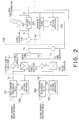
- Figs. 2 and 3 illustration is made about the interference cancellation apparatus which is for use in combination with a diversity receiving system which has two diversity routes.
- the illustrated interference cancellation apparatus is applied to dual diversity receiving system, as is similar to the conventional one illustrated in Fig. 1.
- the apparatus is operable as a decision feedback equalizer (DFE) which is supplied with first and second diversity reception signals 1 and 2 corresponding to the diversity routes to produce an equalized signal.
- DFE decision feedback equalizer
- the interference cancellation apparatus comprises first and second forward transversal filters 101 and 102 which have a plurality of first and second taps, the first and the second forward transversal filters 101 and 102 filtering the first and the second diversity reception signals 1 and 2 into first and second transversal filtered signals Sf 1 and Sf 2 in accordance with first and second controllable tap gains, respectively; first and second tap gain controllers 103 and 104 for controlling the first and the second controllable tap gains with reference to a first error signal ⁇ 1 and a distributed signal distributed in each one of the first and the second taps in accordance with a predetermined adaptive algorithm, such as minimum mean square error (MMSE) algorithm; a backward transversal filter 105 which has a plurality of third taps and which filters a decision signal S d into a third transversal filtered signal S b in accordance with third controllable tap gains; third tap gain controller 106 for controlling the third controllable tap gains with reference to the first error signal 1 and a third distributed signal distributed
- MMSE minimum
- the diversity combining section 158 comprises an adder 108 for calculating a total sum of a first complex multiplied signal Sc 1 and a second complex multiplied signal Sc 2 to produce a total sum signal S p representative of the total sum; first and second complex multipliers 112 and 113 for complexly multiplying the first and the second transversal filtered signals Sf 1 and Sf 2 by the first and the second correlated values ⁇ and ⁇ to produce first and second complex multiplied signals Sc 1 and Sc 2 , respectively; first and second correlators 114 and 115 for correlating the first and the second transversal filtered signals Sf 1 and Sf 2 with a second error signal ⁇ 2 in each of the first and the second diversity routes to produce first and second correlation signals indicative of the first and the second correlated values ⁇ and ⁇ , respectively; and a second error producing unit, such as a subtractor (hereinunder called a third subtractor) 111 for producing the second error signal ⁇ 2 indicative of a difference between the total sum signal S p and the decision
- the above-mentioned equalized signal is a multilevel signal having a plurality of levels greater than two.
- the decision unit 107 detects which one of the levels the multilevel signal has as a decision level to produce a decision signal representative of the decision level.
- the first and the second forward transversal filters 101 and 102 are connected to respective analog to digital (A/D) converters, demodulators, and the like corresponding to respective diversity routes, although they are not shown in Fig. 2.
- A/D analog to digital
- the first and the second forward transversal filters 101 and 102 produces the first and the second transversal filtered signals S f1 and S f2 which are deprived of each pre-cursor distortion thereby, respectively.
- the first and the second transversal filtered signals S f1 and S f2 are diversity combined by the diversity combining section 158 to produce a diversity combined signal Sp.
- the backward transversal filter 105 produces a third transversal filtered signal S b which is deprived of its post-cursor distortion thereby in response to a decision signal S d from the decision unit 107.
- the third transversal filtered signal S b is subtracted by the second subtractor 110 to produce the subtracted signal S r .
- the decision unit 107 produces the decision signal S d and supplies the decision signal S d to the backward transversal filter 105 as an input signal.
- the first subtractor 109 calculates a difference between input and output signals of the decision unit 107, namely, the difference between the subtracted signal S r and the decision signal S d , to produce the first error signal ⁇ 1 .
- the first and the second tap gain controllers 103 and 104 adjust each tap factor of the first and the second transversal filtered signals S f1 and S f2 .
- the third tap gain controller 106 adjusts a tap factor of the third transversal filtered signal S b in response to the first error signal ⁇ 1 .
- the first and the second complex multipliers 112 and 113 carry out each complex multiply to produce first and second complex multiplied signals Sc 1 and Sc 2 .
- the third subtractors 111 calculates a difference between the diversity combined signal S p and the decision signal S d to produce the second error signal ⁇ 2 .
- the first and the second correlators 114 and 115 correlate the second error signal ⁇ 2 and the first and the second transversal filtered signals S f1 and S f2 through each diversity route to produce first and second correlation signals indicative of the first and the second correlated values ⁇ and ⁇ .
- the first and the second correlation signals are supplied to the first and the second complex multipliers 112 and 113 through each diversity route.
- the first and the second complex multipliers 112 and 113 carry out each complex multiply between the first and the second correlated values ⁇ and ⁇ and the first and the second transversal filtered signals S f1 and S f2 to produce the first and the second complex multiplied signals Sc 1 and S c2 .
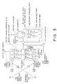
- desired signal wave source 201 having a sampling value S n
- an interference wave source 202 having a sampling value J n
- an impulse response h 2 in the transmission system responsive to the second diversity reception signal 2 at the sampling value S n an impulse response g 1 in the transmission system responsive to the first diversity reception signal 1 at the sampling value J n
- threefold shift registers 211 and 212 each of which has T/2 interval (T: symbolic cycle)
- first and second multiplier groups 213 and 214 each of which consists of three multipliers
- a twofold shift register 215 which has T interval
- a third multiplier group 216 which consists of two multipliers, first and second adders 217 and 218, a decision unit 107, first, second, and third subtractors 109, 110, and 111.
- tap factor vectors produced by the first and the second tap gain controllers 103 and 104 are depicted by C' and W', respectively.
- the first diversity reception signal 1 is defined as a first input signal r 1 in Fig. 2.
- the r 1 is multiplied with the tap factor vector C' by the convolution processing on the first forward transversal filter 101.
- the first transversal filtered signal S f1 comes to be representative of r 1 *C'.
- the first transversal filtered signal S f1 is then multiplied with the tap factor ⁇ on the first complex multiplier 112. Consequently, the first complex multiplied signal Sc 1 comes to be representative of r 1 * ⁇ C'.
- the second diversity reception signal 2 is defined as a second input signal r 2 in Fig. 2.
- the r 2 is multiplied with the tap factor vector W' by the convolution processing on the second forward transversal filter 102.
- the second transversal filtered signal S f2 comes to be representative of r 2 *W'.
- the second transversal filtered signal S f2 is then multiplied with the tap factor ⁇ on the second complex multiplier 113 Consequently, the second complex multiplied signal Sc 2 comes to be representative of r 2 * ⁇ W'.
- the desired wave signals 201(S n ) and 202(J n ) are broad-band modulated signals independent from each other, and that mutual correlation between symbols which are spaced from each other by more than one symbol is null. It is also assumed that Rayleigh fadings which are independent from each other are added to the impulse responses h 1 , h 2 , g 1 , and g 2 .
- C, W, D represent tap factor vectors of the first and the second forward transversal filters 101 and 102, and the backward transversal filter 105, respectively.
- Each of C, W, D is represented by the following equation (9).
- h 1 and h 2 represent sampling value vectors of impulse responses h 1 and h 2 , respectively.
- Each of h 1 and h 2 is represented by the following equation (10).
- the left-side of the normal equation is a correlated matrix of the Monsen's DFE.
- the correlated matrix of the Monsen's DFE is 8 x 8 in size, when applied to the system illustrated in Fig. 3.
- a performance function ⁇ at the time n based on mean square value of the first error signal is represented by the following equation (11).
- ⁇ min represents a critical minimum value of the performance function
- ⁇ 0 represents an error vector between an initial value and an ideal solution concerning all the taps
- q i represents an intrinsic vector concerning the tap of i turn
- ⁇ i represents an eigenvalue in the correlated matrix of 8 x 8
- ⁇ represents a tap adjusting factor in the LMS algorithm.
- the second error signal 2 produced by the third subtractor 111 there is introduced the second error signal 2 produced by the third subtractor 111, as illustrated in Fig. 2. Consequently, there is introduced a secondary MMSE correlated loop which comprises the first and the second correlators 114 and 115, and the first and the second complex multipliers 112 and 113 in addition to the primary MMSE correlated loop.
- tap factors ⁇ and ⁇ multiplied by the first and the second complex multipliers 112 and 113 are sequentially renewed so that mean square value of the second error signal ⁇ 2 may be minimized.
- the secondary MMSE correlated loop is equal to an LMS correlated loop which is often used in an adaptive array.
- the secondary MMSE correlated loop is similar in operation to a nulling in an antenna pattern against undesired interfering and disturbing waves. Namely, in the secondary MMSE correlated loop, the tap factors ⁇ and ⁇ are controlled so that interfering waves in diversity routes may be cancelled each other at a reciprocal condition.
- the LMS array provides a fast convergence characteristic under such severe circumstances that desired to undesired signals ratio (D/U) comes to be negative.
- D/U desired to undesired signals ratio
- the secondary MMSE correlated loop responses more sensitively to the interfering and disturbing waves than to the multipath distortion.
- first and the second complex multipliers 112 and 113 are not transversal filters and so that operations of the first and the second complex multipliers 112 and 113 are restricted to a control of amplitudes and phases of the diversity input signals.
- the first and the second complex multipliers 112 and 113 are not capable of such a transversal filtering adaptive equalization.
- the first and the second complex multipliers 112 and 113 are absorbed in an anti-phase combination of the interfering and disturbing waves.
- the primary MMSE correlated loop with the first error signal ⁇ 1 there is carried out an adjustment of the tap factors of the first and the second forward transversal filters 101 and 102, and the backward transversal filter 105 so that multipath distortion due to variable elements h 1 and g 2 in the propagation paths may be removed.
- the secondary MMSE correlated loop with the second error signal ⁇ 2 there is carried out an anti-phase cancellation of received interfering waves which is due to variable elements h 2 and g 1 in the propagation paths.
- the first MMSE control system is for use in the adaptive equalization while the second MMSE control system is for use in the interference cancellation.
- the adaptive equalization and the interference cancellation can be parallely processed at the same time. Consequently, both the adaptive equalization and the interference cancellation can be carried out at a high speed in the interference cancellation apparatus of the present invention, as compared with the conventional one.
- the interference cancellation apparatus may be subjected to an environment in which the above-mentioned interfering waves are more fastly variable than the multipath waves.
- the response speed of the second MMSE control system should be predetermined to be larger than that of the first MMSE control system.
- the adjusting factor of the second MMSE control system should be made larger than that of the first MMSE control system, with respect to algorithms, such as the aforesaid LMS algorithm, for adjusting the tap factors.
- algorithms such as the aforesaid LMS algorithm
- a component indicating such electric power in a correlated matrix is generally called a "trace".
- the "trace” is defined by the equation (12).
- an MMSE control system with an LMS algorithm must comply with the following inequality (13) so as to be converged. 0 ⁇ ⁇ ⁇ (2/tr[R])
- the eigenvalue is decreased by the quantity of the electric power of the interfering waves. Consequently, it is possible that the value of the right part, (2/tr[R]) in the inequality (13) becomes large. It is therefore not necessary that the adjusting factor ⁇ in the first MMSE control system is made too small. Accordingly, the convergence performance of the first MMSE control system is not so deteriorated.
- the adaptive equalization and the interference cancellation are processed in parallel by the first and the second MMSE control systems, so that the control of the adaptive equalization and the interference cancellation can be converged at a high speed.
- an excellent performance of both the adaptive equalization and the interference cancellation is achieved with respect not only to interferring waves which are variable faster than those of multipath fading but also to interfering waves by which the aforesaid D/U ratio becomes negative.
- the equalized signal may be a binary signal specified by a binary level.
- the decision unit 107 detects whether or not the binary level of the equalized signal exceeds a predetermined threshold level to decide a detected binary level for the equalized signal and to produce a decision signal representative of the judged binary level.
Landscapes
- Engineering & Computer Science (AREA)
- Computer Networks & Wireless Communication (AREA)
- Signal Processing (AREA)
- Power Engineering (AREA)
- Radio Transmission System (AREA)
- Filters That Use Time-Delay Elements (AREA)
- Cable Transmission Systems, Equalization Of Radio And Reduction Of Echo (AREA)
Claims (5)
- Interferenzunterdrückungsvorrichtung zur Verwendung in Kombination mit einem Diversity-Empfangssystem, wobei die Vorrichtung mit ersten und zweiten Diversity-Empfangssignalen (1 und 2)versorgt ist und als ein Entscheidungsrückkopplungsentzerrer betreibbar ist zum Erzeugen eines entzerrten Signals, wobei die Vorrichtung aufweist:wobei die ersten und zweiten Transversalmittel (101 und 102), ersten und zweiten Steuermittel (103 und 104), dritten Transversalfiltermittel (105), dritten Steuermittel (106), Entscheidungsmittel (107), erste Substrahiermittel (109) und zweite Subtrahiermittel (110) betreibbar sind als eine erste Regelschleife zum Steuern der ersten und zweiten steuerbaren Anzapfungsgewinne und den dritten steuerbaren Anzapfungsgewinne unter Berücksichtigung des ersten Fehlersignals (ε1);erste und zweite Transversalfiltermittel (101 und 102) zum Filtern der ersten und zweiten Diversity-Empfangssignale (1 und 2) zu ersten und zweiten transversal gefilterten Signalen (Sf1 und Sf2) in Übereinstimmung mit ersten bzw. zweiten steuerbaren Anzapfungsgewinnen;erste und zweite Steuermittel (103 und 104) zum Steuern der ersten und zweiten steuerbaren Anzapfungsgewinne unter Berücksichtigung eines ersten Fehlersignals (ε1) in Übereinstimmung mit einem vorbestimmten adaptiven Algorithmus;dritte Transversalfiltermittel (105) zum Filtern eines Entscheidungssignals (Sd) zu einem dritten transversal gefilterten Signal (Sb) in Übereinstimmung mit dritten steuerbaren Anzapfungsgewinnen;dritte Steuermittel (106) zum Steuern der dritten steuerbaren Anzapfungsgewinne unter Berücksichtigung des ersten Fehlersignals (ε1) in Übereinstimmung mit dem vorbestimmten adaptiven Algorithmus;Entscheidungsmittel (107) zum Ermitteln eines Werts des entzerrten Signals als ein Entscheidungswert zum Erzeugen eines Entscheidungssignals (Sd), welches den Entscheidungswert repräsentiert, und zum Anlegen des Entscheidungssignals (Sd) an die dritten Transversalfiltermittel (105);erste Subtrahiermittel (109) zum Erzeugen des ersten Fehlersignals (ε1), welches einen Unterschied zwischen einem subtrahierten Signal (Sr) und dem Entscheidungssignal (Sd) anzeigt, wobei das erste Fehlersignal (ε1) an die ersten, zweiten und dritten Steuermittel (103, 104 und 105) angelegt ist;Diversity-Kombiniermittel (158) zum Kombinieren der ersten und zweiten transversal gefilterten Signale (Sf1) und (Sf2) zum Erzeugen eines kombinierten Signals (Sp); undzweite Subtrahiermittel (110) zum Subtrahieren des dritten transversal gefilterten Signals (Sb) von den kombinierten Signal (Sp) zum Anlegen des subtrahierten Signals (Sr) an die Entscheidungsmittel (107) und die ersten Subtrahiermittel (109);
dadurch gekennzeichnet, daß die Diversity-Kombiniermittel (158) als eine zweite Regelschleife betreibbar sind und umfassenAddiermittel (108) zum Berechnen einer Gesamtsumme eines ersten komplexen multiplizierten Signals (Sc1) und eines zweiten komplexen multiplizierten Signals (Sc2) zum Erzeugen eines Gesamtsummensignals als das kombinierte Signal (Sp), welches die Gesamtsumme repräsentiert;erste und zweite komplexe Multipliziermittel (112 und 113) zum komplexen Multiplizieren der ersten und zweiten transversal gefilterten Signale (Sf1 und Sf2) mit ersten und zweiten korrelierten Werten α und β, um die ersten bzw. zweiten komplexen multiplizierten Signale (Sc1 bzw. Sc2) zu erzeugen;erste und zweite Korreliationsmittel (114 und 115) zum Korrelieren der ersten und zweiten transversal gefilterten Signale (Sf1 und Sf2) mit einem zweiten Fehlersignal (ε2) in jedem der beiden, dem ersten und zweiten Diversitypfad zum Erzeugen von ersten und zweiten Korrelationssignalen, welche die ersten und zweiten korrelierten Werte α bzw. β darstellen; unddritte Subtrahiermittel (111) zum Erzeugen des zweiten Fehlersignals (ε2) welches eine Differenz zwischen dem Gesamtsummensignal (Sp) und dem Entscheidungssignal (Sd) anzeigt, wobei das zweite Fehlersignal (ε2) an die ersten bzw. zweiten Korrelationsmittel (114 und 115) angelegt ist. - Interferenzunterdrückungsvorrichtung nach Anspruch 1, dadurch gekennzeichnet, daß der vorbestimmte adaptive Algorithmus ein minimum-mean-square-Fehler-Algorithmus ist, und die zweite Regelschleife betrieben ist in Übereinstimmung mit einem zusätzlichen vorbestimmten adaptiven Algorithmus des minimum-mean-square-Fehler-Algorithmus.
- Vorrichtung nach einem der vorhergehenden Ansprüche, dadurch gekennzeichnet, daß das Diversity-Empfangssystem erste und zweite Diversitypfade aufweist, wobei erste und zweite Diversity-Empfangssignale (1) und (2) den ersten und zweiten Diversitypfaden entsprechen, und wobei erste und zweiten Transversalfiltermittel (101 und 102) mit einer Mehrzahl von ersten und zweiten Anzapfungen versehen sind,die ersten und zweiten Steuermittel (103 und 104) die ersten und zweiten steuerbaren Anzapfungsgewinne unter Berücksichtigung des ersten Fehlersignals (ε1) und ferner unter Berücksichtigung eines verteilten Signals steuern, daß in jede der beiden, der ersten und zweiten, Anzapfungen in Übereinstimmung mit einem vorbestimmten adaptiven Algorithmus verteilt ist;dritte Transversalfiltermittel (105) mit einer Mehrzahl von dritten Anzapfungen versehen sind unddie dritten Steuermittel (106) die dritte steuerbare Anzapfungsgewinne unter Berücksichtigung des ersten Fehlersignals (ε1) und ferner unter Berücksichtigung eines dritten verteilten Signals steuern, welches in jeder der dritten Anzapfungen in Übereinstimmung mit den vorbestimmten adaptiven Algorithmus verteilt ist.
- Interferenzunterdrückungsvorrichtung nach einem der vorhergehenden Ansprüche, dadurch gekennzeichnet, daß das entzerrte Signal ein binäres Signal ist, welches mittels eines binären Werts spezifiziert ist, wobei die Entscheidungsmittel ermitteln, ob oder ob nicht der binäre Wert des entzerrten Signals einen vorbestimmten Stellenwert überschreitet, um über einen erkannten Binärwert für das entzerrte Signal zu entscheiden und um ein Entscheidungssignal zu erzeugen, das für den ermittelten Binärwert repräsentativ ist.
- Interferenzunterdrückungsvorrichtung nach einem der Ansprüche 1-3, dadurch gekennzeichnet, daß das entzerrte Signal ein Multilevelsignal mit einer Mehrzahl von Werten größer als zwei ist, wobei die Entscheidungsmittel einen der Werte des Multilevelsignals als einen Entscheidungswert ermitteln, um ein Entscheidungssignal zu erzeugen, welches für den Entscheidungswert repräsentativ ist.
Applications Claiming Priority (3)
| Application Number | Priority Date | Filing Date | Title |
|---|---|---|---|
| JP15543993 | 1993-06-25 | ||
| JP5155439A JP2885612B2 (ja) | 1993-06-25 | 1993-06-25 | 干渉波除去装置 |
| JP155439/93 | 1993-06-25 |
Publications (2)
| Publication Number | Publication Date |
|---|---|
| EP0631399A1 EP0631399A1 (de) | 1994-12-28 |
| EP0631399B1 true EP0631399B1 (de) | 2002-03-13 |
Family
ID=15606063
Family Applications (1)
| Application Number | Title | Priority Date | Filing Date |
|---|---|---|---|
| EP94304600A Expired - Lifetime EP0631399B1 (de) | 1993-06-25 | 1994-06-24 | Verfahren und Vorrichtung zur Interferenzunterdrückung und adaptiven Entzerrung bei Diversityempfang |
Country Status (3)
| Country | Link |
|---|---|
| US (1) | US5524125A (de) |
| EP (1) | EP0631399B1 (de) |
| JP (1) | JP2885612B2 (de) |
Cited By (16)
| Publication number | Priority date | Publication date | Assignee | Title |
|---|---|---|---|---|
| US7071776B2 (en) | 2001-10-22 | 2006-07-04 | Kyocera Wireless Corp. | Systems and methods for controlling output power in a communication device |
| US7116954B2 (en) | 2001-04-11 | 2006-10-03 | Kyocera Wireless Corp. | Tunable bandpass filter and method thereof |
| US7154440B2 (en) | 2001-04-11 | 2006-12-26 | Kyocera Wireless Corp. | Phase array antenna using a constant-gain phase shifter |
| US7164329B2 (en) | 2001-04-11 | 2007-01-16 | Kyocera Wireless Corp. | Tunable phase shifer with a control signal generator responsive to DC offset in a mixed signal |
| US7174147B2 (en) | 2001-04-11 | 2007-02-06 | Kyocera Wireless Corp. | Bandpass filter with tunable resonator |
| US7176845B2 (en) | 2002-02-12 | 2007-02-13 | Kyocera Wireless Corp. | System and method for impedance matching an antenna to sub-bands in a communication band |
| US7180467B2 (en) | 2002-02-12 | 2007-02-20 | Kyocera Wireless Corp. | System and method for dual-band antenna matching |
| US7184727B2 (en) | 2002-02-12 | 2007-02-27 | Kyocera Wireless Corp. | Full-duplex antenna system and method |
| US7221243B2 (en) | 2001-04-11 | 2007-05-22 | Kyocera Wireless Corp. | Apparatus and method for combining electrical signals |
| US7248845B2 (en) | 2004-07-09 | 2007-07-24 | Kyocera Wireless Corp. | Variable-loss transmitter and method of operation |
| US7394430B2 (en) | 2001-04-11 | 2008-07-01 | Kyocera Wireless Corp. | Wireless device reconfigurable radiation desensitivity bracket systems and methods |
| EP2015468A1 (de) * | 2007-07-10 | 2009-01-14 | SIAE Microelettronica S.p.A. | Basisbandkombinator für digitale Funkverbindungen |
| US7548762B2 (en) | 2005-11-30 | 2009-06-16 | Kyocera Corporation | Method for tuning a GPS antenna matching network |
| US7720443B2 (en) | 2003-06-02 | 2010-05-18 | Kyocera Wireless Corp. | System and method for filtering time division multiple access telephone communications |
| US7746292B2 (en) | 2001-04-11 | 2010-06-29 | Kyocera Wireless Corp. | Reconfigurable radiation desensitivity bracket systems and methods |
| US7916806B2 (en) | 1997-09-16 | 2011-03-29 | At&T Mobility Ii Llc | Transmitter diversity technique for wireless communications |
Families Citing this family (46)
| Publication number | Priority date | Publication date | Assignee | Title |
|---|---|---|---|---|
| DE4434723C1 (de) * | 1994-09-28 | 1995-06-14 | Siemens Ag | Adaptives Netzwerk |
| JP3287971B2 (ja) * | 1995-01-31 | 2002-06-04 | 松下電器産業株式会社 | データ受信装置 |
| JP3325735B2 (ja) * | 1995-01-31 | 2002-09-17 | 松下電器産業株式会社 | データ受信装置 |
| JP3270289B2 (ja) * | 1995-03-15 | 2002-04-02 | 日本電気株式会社 | 判定帰還形等化器 |
| JPH08315511A (ja) * | 1995-05-18 | 1996-11-29 | Fujitsu Ltd | 判定フィードバック・イコライザ及び2入力判定スライス設定方法 |
| EP0813301A1 (de) * | 1996-06-10 | 1997-12-17 | TOSHIBA Electronics Europe GmbH | Digitales adaptives Filter |
| FR2750270B1 (fr) * | 1996-06-21 | 1998-08-07 | Alcatel Telspace | Egaliseur-combineur pour recepteur en diversite, recepteur integrant un tel egaliseur-combineur, et procede de reception en diversite correspondant |
| US6067319A (en) * | 1996-09-04 | 2000-05-23 | Integrated Device Technology, Inc. | Method for equalization of a quadrature amplitude modulated signal |
| KR100470009B1 (ko) * | 1996-09-18 | 2005-06-01 | 코닌클리케 필립스 일렉트로닉스 엔.브이. | 간섭검출회로,간섭검출방법,수신기및fm수신기 |
| KR100226698B1 (ko) * | 1996-12-28 | 1999-10-15 | 전주범 | 직교 주파수 분할 다중화 수신 시스템의 채널 등화 장치 |
| JP2980053B2 (ja) * | 1997-03-28 | 1999-11-22 | 日本電気株式会社 | 干渉波除去装置 |
| EP0872964A1 (de) * | 1997-04-09 | 1998-10-21 | Nec Corporation | Verfahren und Vorrichtung zum verbesserten Diversity-Empfang in einem digitalen Radiokommunikationssystem |
| US5901343A (en) * | 1997-05-09 | 1999-05-04 | Lockheed Martin Corporation | Adaptive cross polarization Interference canceler for use at intermediate frequencies |
| US6101228A (en) * | 1997-05-22 | 2000-08-08 | Conexant Systems, Inc. | Receiver of wideband digital signal in the presence of a narrow band interfering signal |
| DE69839960D1 (de) * | 1997-06-03 | 2008-10-16 | Nippon Telegraph & Telephone | Adaptive gruppensender/empfänger |
| CA2276207C (en) | 1997-10-31 | 2003-02-18 | At&T Wireless Services, Inc. | Low complexity maximum likelihood detection of concatenated space codes for wireless applications |
| US6144697A (en) * | 1998-02-02 | 2000-11-07 | Purdue Research Foundation | Equalization techniques to reduce intersymbol interference |
| US6327302B1 (en) * | 1998-08-28 | 2001-12-04 | Ericsson Inc. | Fast adaptive equalizer for wireless communication systems |
| US6320919B1 (en) | 1998-11-30 | 2001-11-20 | Ericsson Inc. | Adaptive channel characterization using decoded symbols |
| EP1157474A1 (de) * | 1999-03-10 | 2001-11-28 | Nokia Mobile Phones Ltd. | Nichtüberwachter, anpassbarer chiptrennfilter für cdma endstation |
| JP2001203619A (ja) * | 2000-01-19 | 2001-07-27 | Matsushita Electric Ind Co Ltd | 無線基地局装置及び無線通信方法 |
| JP4581288B2 (ja) * | 2000-05-09 | 2010-11-17 | パナソニック株式会社 | 復調器 |
| US7116730B2 (en) * | 2000-05-09 | 2006-10-03 | Matsushita Electric Industrial Co., Ltd. | Demodulation apparatus |
| US20020106040A1 (en) * | 2001-02-02 | 2002-08-08 | Sarnoff Corporation | Method and apparatus for reducing multipath distortion in a wireless ian system |
| AU2001264906A1 (en) * | 2000-05-22 | 2001-12-03 | Sarnoff Corporation | Method and apparatus for reducing multipath distortion in a wireless lan system |
| US6480151B2 (en) | 2000-12-29 | 2002-11-12 | Lockheed Martin Corporation | GPS receiver interference nuller with no satellite signal distortion |
| US6819911B2 (en) | 2001-04-02 | 2004-11-16 | General Dynamics Decision Systems, Inc. | Active interference suppressor utilizing recombinant transmultiplexing |
| US6990137B2 (en) | 2001-05-17 | 2006-01-24 | Qualcomm, Incorporated | System and method for received signal prediction in wireless communications systems |
| US7170924B2 (en) | 2001-05-17 | 2007-01-30 | Qualcomm, Inc. | System and method for adjusting combiner weights using an adaptive algorithm in wireless communications system |
| US7133477B2 (en) * | 2002-01-02 | 2006-11-07 | Intel Corporation | Robust low complexity multi-antenna adaptive minimum mean square error equalizer |
| US6993311B2 (en) * | 2002-02-20 | 2006-01-31 | Freescale Semiconductor, Inc. | Radio receiver having an adaptive equalizer and method therefor |
| EP1512025B1 (de) * | 2002-06-11 | 2007-03-28 | Worcester Polytechnic Institute | Rekonfigurierbares geolokationssystem |
| US6697424B1 (en) * | 2003-05-06 | 2004-02-24 | Industrial Technology Research Institute | Fast convergent pipelined adaptive decision feedback equalizer using post-cursor processing filter |
| JP4213023B2 (ja) * | 2003-05-29 | 2009-01-21 | 富士通株式会社 | 適応制御装置及び適応制御方法 |
| US7369607B2 (en) * | 2004-02-26 | 2008-05-06 | 2Wire, Inc. | Multicarrier communication using a time domain equalizing filter |
| US8194722B2 (en) * | 2004-10-11 | 2012-06-05 | Broadcom Corporation | Various methods and apparatuses for impulse noise mitigation |
| US7953163B2 (en) * | 2004-11-30 | 2011-05-31 | Broadcom Corporation | Block linear equalization in a multicarrier communication system |
| US7852950B2 (en) * | 2005-02-25 | 2010-12-14 | Broadcom Corporation | Methods and apparatuses for canceling correlated noise in a multi-carrier communication system |
| US9374257B2 (en) * | 2005-03-18 | 2016-06-21 | Broadcom Corporation | Methods and apparatuses of measuring impulse noise parameters in multi-carrier communication systems |
| JP4693462B2 (ja) * | 2005-03-31 | 2011-06-01 | 富士通テン株式会社 | ダイバシティ受信装置および方法 |
| US7813439B2 (en) * | 2006-02-06 | 2010-10-12 | Broadcom Corporation | Various methods and apparatuses for impulse noise detection |
| WO2009113462A1 (ja) * | 2008-03-11 | 2009-09-17 | 日本電気株式会社 | 波形等化回路および波形等化方法 |
| US8605837B2 (en) * | 2008-10-10 | 2013-12-10 | Broadcom Corporation | Adaptive frequency-domain reference noise canceller for multicarrier communications systems |
| IT1393478B1 (it) * | 2009-04-02 | 2012-04-27 | Siae Microelettronica Spa | Sistema di protezione per ponti radio digitali a modulazione adattativa operanti in diversita' |
| PL226101B1 (pl) * | 2015-02-10 | 2017-06-30 | Sławomir Szechniuk | Sposob redukcji zaklocen i szumow w ukladach z dwoma torami sygnalow oraz filtr fazowy |
| CN110146848B (zh) * | 2019-05-22 | 2023-06-23 | 西安电子科技大学 | 基于分数阶最小均方的调频连续波雷达自干扰消除方法 |
Family Cites Families (5)
| Publication number | Priority date | Publication date | Assignee | Title |
|---|---|---|---|---|
| JPS5927133B2 (ja) * | 1979-02-21 | 1984-07-03 | 日本電気株式会社 | 適応型受信機 |
| US4281411A (en) * | 1979-06-25 | 1981-07-28 | Signatron, Inc. | High speed digital communication receiver |
| JP2503715B2 (ja) * | 1990-03-30 | 1996-06-05 | 日本電気株式会社 | 適応受信機 |
| JP2982504B2 (ja) * | 1992-07-31 | 1999-11-22 | 日本電気株式会社 | 適応受信機 |
| JP2780576B2 (ja) * | 1992-08-05 | 1998-07-30 | 日本電気株式会社 | 干渉波除去装置 |
-
1993
- 1993-06-25 JP JP5155439A patent/JP2885612B2/ja not_active Expired - Fee Related
-
1994
- 1994-06-24 EP EP94304600A patent/EP0631399B1/de not_active Expired - Lifetime
- 1994-06-27 US US08/265,754 patent/US5524125A/en not_active Expired - Fee Related
Cited By (23)
| Publication number | Priority date | Publication date | Assignee | Title |
|---|---|---|---|---|
| US8355475B2 (en) | 1997-09-16 | 2013-01-15 | At&T Mobility Ii Llc | Diversity technique for wireless communications |
| US9203499B2 (en) | 1997-09-16 | 2015-12-01 | At&T Mobility Ii Llc | Transmitter diversity technique for wireless communications |
| US7916806B2 (en) | 1997-09-16 | 2011-03-29 | At&T Mobility Ii Llc | Transmitter diversity technique for wireless communications |
| US8237620B2 (en) | 2001-04-11 | 2012-08-07 | Kyocera Corporation | Reconfigurable radiation densensitivity bracket systems and methods |
| US7174147B2 (en) | 2001-04-11 | 2007-02-06 | Kyocera Wireless Corp. | Bandpass filter with tunable resonator |
| US7164329B2 (en) | 2001-04-11 | 2007-01-16 | Kyocera Wireless Corp. | Tunable phase shifer with a control signal generator responsive to DC offset in a mixed signal |
| US7746292B2 (en) | 2001-04-11 | 2010-06-29 | Kyocera Wireless Corp. | Reconfigurable radiation desensitivity bracket systems and methods |
| US7154440B2 (en) | 2001-04-11 | 2006-12-26 | Kyocera Wireless Corp. | Phase array antenna using a constant-gain phase shifter |
| US7221327B2 (en) | 2001-04-11 | 2007-05-22 | Kyocera Wireless Corp. | Tunable matching circuit |
| US7221243B2 (en) | 2001-04-11 | 2007-05-22 | Kyocera Wireless Corp. | Apparatus and method for combining electrical signals |
| US7265643B2 (en) | 2001-04-11 | 2007-09-04 | Kyocera Wireless Corp. | Tunable isolator |
| US7394430B2 (en) | 2001-04-11 | 2008-07-01 | Kyocera Wireless Corp. | Wireless device reconfigurable radiation desensitivity bracket systems and methods |
| US7116954B2 (en) | 2001-04-11 | 2006-10-03 | Kyocera Wireless Corp. | Tunable bandpass filter and method thereof |
| US7509100B2 (en) | 2001-04-11 | 2009-03-24 | Kyocera Wireless Corp. | Antenna interface unit |
| US7071776B2 (en) | 2001-10-22 | 2006-07-04 | Kyocera Wireless Corp. | Systems and methods for controlling output power in a communication device |
| US7176845B2 (en) | 2002-02-12 | 2007-02-13 | Kyocera Wireless Corp. | System and method for impedance matching an antenna to sub-bands in a communication band |
| US7184727B2 (en) | 2002-02-12 | 2007-02-27 | Kyocera Wireless Corp. | Full-duplex antenna system and method |
| US7180467B2 (en) | 2002-02-12 | 2007-02-20 | Kyocera Wireless Corp. | System and method for dual-band antenna matching |
| US7720443B2 (en) | 2003-06-02 | 2010-05-18 | Kyocera Wireless Corp. | System and method for filtering time division multiple access telephone communications |
| US8478205B2 (en) | 2003-06-02 | 2013-07-02 | Kyocera Corporation | System and method for filtering time division multiple access telephone communications |
| US7248845B2 (en) | 2004-07-09 | 2007-07-24 | Kyocera Wireless Corp. | Variable-loss transmitter and method of operation |
| US7548762B2 (en) | 2005-11-30 | 2009-06-16 | Kyocera Corporation | Method for tuning a GPS antenna matching network |
| EP2015468A1 (de) * | 2007-07-10 | 2009-01-14 | SIAE Microelettronica S.p.A. | Basisbandkombinator für digitale Funkverbindungen |
Also Published As
| Publication number | Publication date |
|---|---|
| EP0631399A1 (de) | 1994-12-28 |
| JPH0715381A (ja) | 1995-01-17 |
| US5524125A (en) | 1996-06-04 |
| JP2885612B2 (ja) | 1999-04-26 |
Similar Documents
| Publication | Publication Date | Title |
|---|---|---|
| EP0631399B1 (de) | Verfahren und Vorrichtung zur Interferenzunterdrückung und adaptiven Entzerrung bei Diversityempfang | |
| US5119401A (en) | Decision feedback equalizer including forward part whose signal reference point is shiftable depending on channel response | |
| EP0720334B1 (de) | Entscheidungsrückgekoppelter Entzerrer zur Auslösung von kurzen und langen Mehrpfadkomponenten, unter Verwendung von entsprechend verzörgerten Entscheidungssymbolen | |
| EP0680154B1 (de) | Interferenzunterdrückung mit einer leistungsinvertierenden adaptiven Antennenanordnung und einem adaptiven Entzerrer nach dem Verfahren des kleinsten quadratischen Fehlers | |
| US6144697A (en) | Equalization techniques to reduce intersymbol interference | |
| US4328585A (en) | Fast adapting fading channel equalizer | |
| EP0684706B1 (de) | Replikherstellendes adaptives demodulationsverfahren und dieses verwendender demodulator | |
| JP2669393B2 (ja) | 干渉波除去装置 | |
| EP0757456B1 (de) | Diversity-Empfänger | |
| US20020150155A1 (en) | Convergence speed, lowering the excess noise and power consumption of equalizers | |
| EP1413106B1 (de) | Entzerrer mit software definierbarer Blockweiser Anpassung der Entscheidungsrückkopplung | |
| EP1624634A2 (de) | Verfahren und Einrichtung zum Empfangen von Signalen in einem MIMO-System | |
| KR19990076683A (ko) | 다이버시티 신호의 어레이 프로세싱을 사용하여심볼간 간섭을 줄이는 방법 및 장치 | |
| US20050232347A1 (en) | Apparatus and method for noise enhancement reduction in an adaptive equalizer | |
| EP1530300B1 (de) | Verfahren und Vorrichtung zur Entzerrerung in einem Empfänger eines CDMA Systems | |
| EP1563657B1 (de) | Entzerrer zur abtastwertweisen entscheidungsrueckmeldung im transformationsbereich | |
| US20070165735A1 (en) | Method and apparatus for supporting transmit diversity in a receiver | |
| US6650702B1 (en) | Blind initialization of decision feedback equalizer using an antenna array | |
| KR100202944B1 (ko) | 에러 궤환을 이용한 결정 궤환 등화기 | |
| JP2503715B2 (ja) | 適応受信機 | |
| US7535954B2 (en) | Method and apparatus for performing channel equalization in communication systems | |
| EP0690589B1 (de) | Anordnung zur Kompensation der Interferenz in einem digitalen Mikrowellenrelaissystem | |
| JPH03284014A (ja) | 判定帰還形等化器 | |
| KR100767692B1 (ko) | 등화기 | |
| US20070260659A1 (en) | Computing Filter Coefficients for an Equalizer in a Communication Receiver |
Legal Events
| Date | Code | Title | Description |
|---|---|---|---|
| PUAI | Public reference made under article 153(3) epc to a published international application that has entered the european phase |
Free format text: ORIGINAL CODE: 0009012 |
|
| AK | Designated contracting states |
Kind code of ref document: A1 Designated state(s): FR GB IT |
|
| 17P | Request for examination filed |
Effective date: 19941018 |
|
| 17Q | First examination report despatched |
Effective date: 19980310 |
|
| GRAG | Despatch of communication of intention to grant |
Free format text: ORIGINAL CODE: EPIDOS AGRA |
|
| GRAG | Despatch of communication of intention to grant |
Free format text: ORIGINAL CODE: EPIDOS AGRA |
|
| GRAG | Despatch of communication of intention to grant |
Free format text: ORIGINAL CODE: EPIDOS AGRA |
|
| GRAH | Despatch of communication of intention to grant a patent |
Free format text: ORIGINAL CODE: EPIDOS IGRA |
|
| GRAH | Despatch of communication of intention to grant a patent |
Free format text: ORIGINAL CODE: EPIDOS IGRA |
|
| REG | Reference to a national code |
Ref country code: GB Ref legal event code: IF02 |
|
| GRAA | (expected) grant |
Free format text: ORIGINAL CODE: 0009210 |
|
| AK | Designated contracting states |
Kind code of ref document: B1 Designated state(s): FR GB IT |
|
| ET | Fr: translation filed | ||
| PLBE | No opposition filed within time limit |
Free format text: ORIGINAL CODE: 0009261 |
|
| STAA | Information on the status of an ep patent application or granted ep patent |
Free format text: STATUS: NO OPPOSITION FILED WITHIN TIME LIMIT |
|
| 26N | No opposition filed |
Effective date: 20021216 |
|
| PGFP | Annual fee paid to national office [announced via postgrant information from national office to epo] |
Ref country code: FR Payment date: 20030610 Year of fee payment: 10 |
|
| PGFP | Annual fee paid to national office [announced via postgrant information from national office to epo] |
Ref country code: GB Payment date: 20030618 Year of fee payment: 10 |
|
| PG25 | Lapsed in a contracting state [announced via postgrant information from national office to epo] |
Ref country code: GB Free format text: LAPSE BECAUSE OF NON-PAYMENT OF DUE FEES Effective date: 20040624 |
|
| GBPC | Gb: european patent ceased through non-payment of renewal fee |
Effective date: 20040624 |
|
| PG25 | Lapsed in a contracting state [announced via postgrant information from national office to epo] |
Ref country code: FR Free format text: LAPSE BECAUSE OF NON-PAYMENT OF DUE FEES Effective date: 20050228 |
|
| REG | Reference to a national code |
Ref country code: FR Ref legal event code: ST |
|
| PG25 | Lapsed in a contracting state [announced via postgrant information from national office to epo] |
Ref country code: IT Free format text: LAPSE BECAUSE OF NON-PAYMENT OF DUE FEES Effective date: 20050624 |