EP0631932B1 - Verfahren und Vorrichtung für das automatische Zusammensetzen von becherförmi- gen Körpern - Google Patents
Verfahren und Vorrichtung für das automatische Zusammensetzen von becherförmi- gen Körpern Download PDFInfo
- Publication number
- EP0631932B1 EP0631932B1 EP94109003A EP94109003A EP0631932B1 EP 0631932 B1 EP0631932 B1 EP 0631932B1 EP 94109003 A EP94109003 A EP 94109003A EP 94109003 A EP94109003 A EP 94109003A EP 0631932 B1 EP0631932 B1 EP 0631932B1
- Authority
- EP
- European Patent Office
- Prior art keywords
- bodies
- duct
- elements
- radially
- engagement
- Prior art date
- Legal status (The legal status is an assumption and is not a legal conclusion. Google has not performed a legal analysis and makes no representation as to the accuracy of the status listed.)
- Expired - Lifetime
Links
Images




Classifications
-
- B—PERFORMING OPERATIONS; TRANSPORTING
- B65—CONVEYING; PACKING; STORING; HANDLING THIN OR FILAMENTARY MATERIAL
- B65B—MACHINES, APPARATUS OR DEVICES FOR, OR METHODS OF, PACKAGING ARTICLES OR MATERIALS; UNPACKING
- B65B7/00—Closing containers or receptacles after filling
- B65B7/16—Closing semi-rigid or rigid containers or receptacles not deformed by, or not taking-up shape of, contents, e.g. boxes or cartons
- B65B7/28—Closing semi-rigid or rigid containers or receptacles not deformed by, or not taking-up shape of, contents, e.g. boxes or cartons by applying separate preformed closures, e.g. lids, covers
-
- A—HUMAN NECESSITIES
- A61—MEDICAL OR VETERINARY SCIENCE; HYGIENE
- A61J—CONTAINERS SPECIALLY ADAPTED FOR MEDICAL OR PHARMACEUTICAL PURPOSES; DEVICES OR METHODS SPECIALLY ADAPTED FOR BRINGING PHARMACEUTICAL PRODUCTS INTO PARTICULAR PHYSICAL OR ADMINISTERING FORMS; DEVICES FOR ADMINISTERING FOOD OR MEDICINES ORALLY; BABY COMFORTERS; DEVICES FOR RECEIVING SPITTLE
- A61J3/00—Devices or methods specially adapted for bringing pharmaceutical products into particular physical or administering forms
- A61J3/07—Devices or methods specially adapted for bringing pharmaceutical products into particular physical or administering forms into the form of capsules or similar small containers for oral use
- A61J3/071—Devices or methods specially adapted for bringing pharmaceutical products into particular physical or administering forms into the form of capsules or similar small containers for oral use into the form of telescopically engaged two-piece capsules
- A61J3/074—Filling capsules; Related operations
Definitions
- the present invention relates to apparatus for the assembly of containers and was developed with particular attention to its possible use, for example, in the automatic assembly of containers for small toys, trinkets and the like intended to be inserted as "surprises" in food products or the like.
- the surprise is of a type requiring assembly and a sheet of assembly instructions and/or a sheet of transfers to be applied to the surprise must be put into the container as well as the component parts: usually, this sheet or sheets are rolled into a tube for insertion in one of the two cup-like bodies, in contact with its inner surface.
- the object of the present invention is to provide a solution to the last of the problems described above (that is the automatic assembly of the container), the other problems being solved by arrangements which are the subject of other European patent applications, filed on the same date by the same applicant.
- a container (little barrel), generally indicated 1 is of the type commonly used to hold small toys, trinkets or the like ("surprises"), usually of a type requiring assembly, inside hollow products, for example hollow food products such as confectionery (chocolate eggs and the like).
- surprises small toys, trinkets or the like
- hollow food products for example hollow food products such as confectionery (chocolate eggs and the like).
- the container 1 is usually constituted by two cup-like bodies 2, 3, of flexible plastics material, intended for engagement by their open ends in a general male-female arrangement.
- one of the two bodies has at its open end a cylindrical neck portion 4 intended to penetrate the open end of the other body 2. This is in order to ensure secure end-to-end engagement, which is usually further strengthened by the presence of ribs 4a on the outer surface of the neck portion 4 for engagement in cooperating grooves (not shown in the drawings) in the inner surface of the open end of the body 2.
- the surprise, generally indicated S, is fitted into the body 3 (following various criteria, for example by adopting the solutions described in other patent applications for industrial invention filed on the same date by the same applicant) which is held with its open end upwards.
- the component parts (elements) of the surprise S (put into the container loose 1) project from the neck portion 4 of the body 3.
- the sheets F normally carry the instructions for assembling the surprise and/or transfers for applying to the surprise itself.
- FIG 2 shows an apparatus (collector), generally indicated 10, for use according to the invention in the automatic assembly of containers such as the container 1 of Figure 1.
- the apparatus of the invention is able to close a plurality of containers 1, for example four, simultaneously.
- the apparatus 10 has a plurality of cavities 11 which define respective vertical-axis tubular ducts arranged in a gantry over a conveyor 12 (for example a motor-driven conveyor belt) on which the lower bodies 3 of the containers 1 advance horizontally in trays or pallets 13, the containers having been filled in advance (by means which are assumed to be known) with the surprises S and the sheets F.
- a conveyor 12 for example a motor-driven conveyor belt
- the trays 13 are constituted by matrix-type holding structures with several rows of vertical-axis apertures 14 for holding the bodies 3. In the embodiment illustrated, each row has four apertures 14 on which the apparatus 10 acts simultaneously.
- this result may be achieved by ensuring that the conveyor 12 transports the trays 13 in a direction perpendicular to the longer axis of the apparatus 10 and that the conveyor 12 is advanced (according to well known criteria which do not need to be described here) in such a way that, at each step, a corresponding row of apertures 14 (containing a corresponding row of bodies 3) is brought into alignment with the four vertical-axis cavities 11 in the apparatus 10.
- pusher members lower 15 and upper 16 respectively, constituted by pistons which are driven either pneumatically or electrically (for example electromagnetically).
- the lower pushers 15 pass through corresponding apertures (typically in a plate 12a - Figures 3 to 6) in the conveyor plane in which the conveyor 12 operates.
- the apertured plate 12a interrupts the active conveyor surface of the conveyor 12 itself: it is usually preferred for the conveyor 12, if it is constituted by a belt, to have a continuous surface which is thus free of openings through which the pusher members 15 could pass.
- the function of the pushers 15 is to lift the bodies 3 from the apertures 14 in the trays 13 and to push them up into the chambers 11 in the apparatus 10.
- the purpose of this is to couple them, inside these chambers, with the cooperating upper bodies 2, each of which is carried on the lower end by one of the upper pushers 16.
- the bodies 2 are held on the lower ends of the pushers 16 by suction means, not shown in the drawings.
- the pushers 16 may be able to move horizontally so that they can pick up the upper bodies 2 automatically from a supply, alignment and orientation structure (not shown).
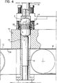
- FIGs 3 to 6 illustrate the structure of the apparatus of the invention in greater detail with specific reference to one only of the chambers 11: it will be understood that the structure illustrated in Figures 3 to 6 is reproduced identically, or almost identically, in all the other chambers of the apparatus 10.
- Each chamber 11 is constituted by a vertical-axis duct whose cross-section corresponds to the cross-section of the containers 1 to be assembled (circular in the embodiment illustrated).
- each chamber 11 includes an upper portion or section 17 and a lower portion or section 18, open to the upper pusher 16 and to the lower pusher 15 respectively.
- the lower portion 18 of the chamber 11 is able to contract radially so that, at rest, its cross-section is at least marginally smaller than the cross-section of the (circular) open ends of the bodies 2 and 3.
- the apparatus 10, or at least the parts constituting the vertical-axis chamber 11, is usually made of a material (such as TEFLON) which is resilient as well as self-lubricating, easily cleaned and suitable for contact with food products.
- a material such as TEFLON
- the lower portion 18 of the chamber 11 has a plurality of resiliently yielding tongues 20 integrally formed with the material defining the chamber 11 and equiangularly spaced around the periphery of the portion 18 itself, the tongues converging, in their unstressed or rest position, towards the inside of the chamber 11 but each being able to open resiliently towards the outside when a body, such as a body 3, moves upwardly through the chamber or duct 11.
- the lower end of each tongue 20 is substantially aligned with the cross circumference of the lower end of the chamber 11 while, in the unstressed condition, the upper end projects distinctly into the chamber 11.
- the inner edges of the various tongues 20 (for example six, each with an angular extent of around 60°) associated with each chamber 11 jointly define, in the unstressed condition shown in Figure 3, a lower portion 18 of the chamber 11 which, starting from a lower opening having the same cross-sectional shape as the apertures 14 in the trays 13, generally tapers upwards (in an approximately frustoconical shape in the embodiment illustrated).
- the flexibility of the tongues 20 means that they offer flexible resistance, with the ability to widen, to any body passing upwardly through the chamber 11 (it will be seen that this is the case for the bodies 3).
- each tongue 20 by an L-shaped body pivoted at its corner about a horizontal axis so that its main arm extends, overall, approximately along the axis of the chamber and its secondary arm extends radially from this axis away from the axis itself, the free end being acted on by resilient means which urge the L-shaped body into a rest position in which the side of the arm facing into the chamber 11 projects into the chamber 11 itself in an arrangement similar to that of the tongues 20.
- the pushers 15 and 16 By controlling the pushers 15 and 16 to move simultaneously or virtually simultaneously (after the pushers have been aligned exactly with the row of apertures 14 holding the bodies 3), it is possible to insert the bodies 2 and 3 into the chambers 11.
- the upper bodies 2 are transferred downwards by the pushers 16 which descend, pushing the bodies 2 into the upper portions 17 of the chambers 11, for example until the open end of each body 2 bears against the upper ends of the tongues 20 which project into each chamber 11.
- the pushers 15 lift the bodies 3 (which contain the surprises S and the sheets F) into the lower portion 18 (see the sequence illustrated in Figures 3 and 4).
- the container 1 When the assembly operation is completed, the container 1 is inside the chamber 11 and can, for example, be returned to the tray 13 in which it was held before by a downward movement of the pusher members 15, 16 ( Figure 6). Should this be desired, the container 1 may also be left for a moment inside the apparatus 10 (where it is held by the resilient action of the tongues 20) and discharged in a different position, possibly after the apparatus 10 as a whole has been moved by the action of additional pusher members.
Landscapes
- Health & Medical Sciences (AREA)
- Veterinary Medicine (AREA)
- Mechanical Engineering (AREA)
- Chemical & Material Sciences (AREA)
- Medicinal Chemistry (AREA)
- Pharmacology & Pharmacy (AREA)
- Life Sciences & Earth Sciences (AREA)
- Animal Behavior & Ethology (AREA)
- General Health & Medical Sciences (AREA)
- Engineering & Computer Science (AREA)
- Public Health (AREA)
- Automobile Manufacture Line, Endless Track Vehicle, Trailer (AREA)
- Control And Other Processes For Unpacking Of Materials (AREA)
- Container Filling Or Packaging Operations (AREA)
- Toys (AREA)
- Specific Conveyance Elements (AREA)
- Supplying Of Containers To The Packaging Station (AREA)
- Auxiliary Devices For And Details Of Packaging Control (AREA)
- Automatic Assembly (AREA)
- Packages (AREA)
- Lining Or Joining Of Plastics Or The Like (AREA)
Claims (20)
- Vorrichtung für das Zusammensetzen von Behältern, die zwei im allgemeinen schalenförmige Körper (2, 3) besitzen, die durch das Eingreifen ihrer offenen Enden zusammenpassen, wobei zumindest ein Körper (3) zum Zeitpunkt des Zusammensetzens Teile (S, F) enthält, die dazu neigen, radial aus dem offenen Ende (4) herauszuragen, wobei die Vorrichtung einen Aufbau aufweist, der einen Kanal (11) bildet, in den sich die Körper (2, 3) aufeinander zu bewegen können, sowie eine Drückeinrichtung aufweist, um die Körper so vorzuschieben, daß sie mit ihren Enden in Eingriff treten, wobei der Kanal (11) zumindest einen Teil (18) enthält, der sich radial so zusammenziehen kann, daß sein Querschnitt im Ruhezustand zumindest ein wenig kleiner als der Umriß der offenen Enden der Körper (2, 3) ist; und
wobei die Drückeinrichtung (15, 16) die Körper (2, 3) in einen Endeingriff im radial zusammenziehbaren Teil (18) vorschiebt, womit während der Eingreifphase der radial zusammenziehbare Teil (18) des Kanals (11) eine Rückhaltekraft auf die Teile (S,F) ausübt, die zum Herausragen neigen, wodurch sichergestellt wird, daß sie radial innerhalb der offenen Enden (4) zurückgehalten werden, so daß die offenen Enden der Körper (2, 3) in Eingriff gebracht werden können, ohne daß die Teile (S, F) dazwischentreten. - Vorrichtung gemäß Anspruch 1, dadurch gekennzeichnet, daß die Vorrichtung einen Tragaufbau (13) für zumindest einen (3) der beiden schalenförmigen Körper (2, 3) aufweist, dadurch gekennzeichnet, daß die Drückeinrichtung (15) auf den zumindest einen Körper (3) wirkt, um ihn aus dem Tragaufbau herauszudrücken, wodurch der Eingriff der Enden außerhalb des Tragaufbaus (13) erfolgt.
- Vorrichtung gemäß Anspruch 2, dadurch gekennzeichnet, daß der Tragaufbau von einer Wanne (13) gebildet wird, die eine Vielzahl von Aufnahmeöffnungen (14) in einem im allgemeinen matrixartigen Aufbau enthält, wobei jede Öffnung zumindest einen Körper (3) aufnehmen kann.
- Vorrichtung gemäß Anspruch 1 oder 3, dadurch gekennzeichnet, daß die Vorrichtung eine Vielzahl von Kanälen (11) aufweist, womit eine Vielzahl von Behältern (1) durch den Eingriff von entsprechenden schalenförmigen Körpern (2, 3) gleichzeitig hergestellt werden kann.
- Vorrichtung gemäß irgendeinem der bisherigen Ansprüche, dadurch gekennzeichnet, daß die Achse des Kanals (11) vertikal verläuft.
- Vorrichtung gemäß irgendeinem der bisherigen Ansprüche, dadurch gekennzeichnet, daß der radial zusammenziehbare Teil (18) von einer Vielzahl von Elementen (20) gebildet wird, die zwischen einer Ruhestellung, in der die Elemente (20) in den Kanal (11) vorspringen, und einer Stellung bewegbar sind, in der sie geöffnet sind, wobei sie durch jene Kraft in diese Stellung gedrückt werden, die der zumindest eine (3) der schalenförmigen Körper auf sie ausübt.
- Vorrichtung gemäß Anspruch 6, dadurch gekennzeichnet, daß die bewegbaren Elemente (20) elastisch nachgebende Elemente sind.
- Vorrichtung gemäß Anspruch 6 oder 7, dadurch gekennzeichnet, daß die bewegbaren Elemente (20) rund um den Umfang des Kanals (11) in gleichen Winkelabständen beabstandet sind.
- Vorrichtung gemäß irgendeinem der bisherigen Ansprüche, dadurch gekennzeichnet, daß die Wände des Kanals (11) aus einem selbstschmierenden Material bestehen.
- Verfahren gemäß irgendeinem der Ansprüche 6 bis 8, dadurch gekennzeichnet, daß die bewegbaren Elemente (20) gemeinsam mit jenem Material hergestellt werden, aus dem der Kanal (11) besteht.
- Verfahren für das Zusammensetzen von Behältern, die zwei im allgemeinen schalenförmige Körper (2, 3) besitzen, die durch das Eingreifen ihrer offenen Enden zusammenpassen, wobei zumindest einer (3) der Körper zum Zeitpunkt des Zusammensetzens Teile (S, F) enthält, die dazu neigen, radial aus dem offenen Ende (4) herauszuragen, wobei das Verfahren folgende Schritte aufweist:- Ausbilden eines Kanals (11), in dem sich die Körper (2, 3) aufeinander zu bewegen (15, 16) können, um den Endeingriff zu erreichen; Wobei der Kanal (11) zumindest einen Teil (18) enthält, der sich radial so zusammenziehen kann, daß sein Querschnitt im Ruhezustand zumindest ein wenig kleiner als der Umriß der offenen Enden der Körper (2, 3) ist; und- Vorschieben (15, 16) der Körper (2, 3) in einen Endeingriff im radial zusammenziehbaren Teil (18), womit während der Eingreifphase der radial zusammenziehbare Teil (18) des Kanals (11) eine Rückhaltekraft auf die Teile (S, F) ausübt, die zum Herausragen neigen, wodurch sie radial innerhalb dieses offenen Endes zurückgehalten werden, und wodurch sichergestellt wird, daß die offenen Enden der Körper (2, 3) in Eingriff gelangen, ohne daß die Teile (S, F) dazwischentreten.
- Verfahren gemäß Anspruch 11, dadurch gekennzeichnet, daß das Verfahren einen Schritt, um einen Tragaufbau (13) für zumindest einen (3) der beiden schalenförmigen Körper (2, 3) zu liefern, sowie einen Schritt aufweist, um den zumindest einen Körper (3) aus dem Tragaufbau (13) herauszudrücken, wodurch der Eingriff der Enden außerhalb des Tragaufbaus (13) erfolgt.
- Verfahren gemäß Anspruch 12, dadurch gekennzeichnet, daß der Tragaufbau von einer Wanne (13) gebildet wird, die eine Vielzahl von Aufnahmeöffnungen (14) in einem im allgemeinen matrixartigen Aufbau enthält, wobei jede Öffnung zumindest einen Körper (3) aufnehmen kann.
- Verfahren gemäß Anspruch 13, dadurch gekennzeichnet, daß eine Vielzahl von Kanälen (11) vorgesehen ist, womit eine Vielzahl von Behältern (1) durch den Endeingriff von entsprechenden schalenförmigen Körpern (2, 3) gleichzeitig hergestellt werden kann.
- Verfahren gemäß irgendeinem der bisherigen Ansprüche 11 bis 14, dadurch gekennzeichnet, daß der Kanal (11) so angeordnet ist, daß seine Achse vertikal verläuft.
- Verfahren gemäß irgendeinem der bisherigen Ansprüche 11 bis 15, dadurch gekennzeichnet, daß das Verfahren einen Schritt aufweist, um eine Vielzahl von Elementen (20) zu liefern, die den radial zusammenziehbaren Teil (18) bilden und zwischen einer Ruhestellung, in der die Elemente (20) in den Kanal (11) vorspringen, und einer Stellung bewegbar sind, in der sie geöffnet sind, wobei sie durch jene Kraft in diese Stellung gedrückt werden, die von zumindest einem schalenförmigen Körper (2, 3) ausgeübt wird.
- Verfahren gemäß Anspruch 16, dadurch gekennzeichnet, daß die bewegbaren Elemente von elastisch nachgebenden Elementen (20) gebildet werden.
- Verfahren gemäß Anspruch 16 oder 17, dadurch gekennzeichnet, daß das Verfahren einen Schritt aufweist, um die bewegbaren Elemente (20) rund um den Umfang des Kanals (11) in gleichen Winkelabständen zu beabstanden.
- Verfahren gemäß irgendeinem der bisherigen Ansprüche 11 bis 13, dadurch gekennzeichnet, daß der Kanal (11) mit Wänden aus einem selbstschmierenden Material hergestellt ist.
- Verfahren gemäß irgendeinem der Ansprüche 16 bis 18, dadurch gekennzeichnet, daß das Verfahren einen Schritt aufweist, um die bewegbaren Elemente (20) gemeinsam mit jenem Material herzustellen, aus dem der Kanal (11) besteht.
Priority Applications (1)
| Application Number | Priority Date | Filing Date | Title |
|---|---|---|---|
| SI9430024T SI0631932T1 (en) | 1993-06-29 | 1994-06-13 | Method and apparatus for the automatic assembly of cup-like bodies |
Applications Claiming Priority (2)
| Application Number | Priority Date | Filing Date | Title |
|---|---|---|---|
| ITTO930469A IT1260882B (it) | 1993-06-29 | 1993-06-29 | Dispositivo per l'assemblaggio di contenitori e relativo procedimento |
| ITTO930469 | 1993-06-29 |
Publications (2)
| Publication Number | Publication Date |
|---|---|
| EP0631932A1 EP0631932A1 (de) | 1995-01-04 |
| EP0631932B1 true EP0631932B1 (de) | 1997-01-08 |
Family
ID=11411585
Family Applications (1)
| Application Number | Title | Priority Date | Filing Date |
|---|---|---|---|
| EP94109003A Expired - Lifetime EP0631932B1 (de) | 1993-06-29 | 1994-06-13 | Verfahren und Vorrichtung für das automatische Zusammensetzen von becherförmi- gen Körpern |
Country Status (8)
| Country | Link |
|---|---|
| EP (1) | EP0631932B1 (de) |
| AT (1) | ATE147340T1 (de) |
| DE (1) | DE4421982C2 (de) |
| DK (1) | DK0631932T3 (de) |
| ES (1) | ES2096975T3 (de) |
| GR (1) | GR3022676T3 (de) |
| IT (1) | IT1260882B (de) |
| SI (1) | SI0631932T1 (de) |
Cited By (1)
| Publication number | Priority date | Publication date | Assignee | Title |
|---|---|---|---|---|
| CN102958809A (zh) * | 2010-06-30 | 2013-03-06 | 魔法生产集团股份有限公司 | 用于充装容器的装置和方法 |
Families Citing this family (6)
| Publication number | Priority date | Publication date | Assignee | Title |
|---|---|---|---|---|
| DE10142442B4 (de) | 2001-08-31 | 2006-04-27 | Siemens Ag | Gehäuse |
| DE202004015171U1 (de) * | 2004-09-29 | 2006-02-23 | Wepa Apothekenbedarf Gmbh & Co Kg | Kapselfüllgerät |
| WO2006092451A1 (es) * | 2005-03-02 | 2006-09-08 | Discapa, Sl | Instalación y método para el llenado, ensamblado y precintado de cápsulas, y elemento portador y cápsula aplicable a tal instalación |
| IT1399806B1 (it) | 2009-03-27 | 2013-05-03 | Magic Production Group S A | Articolo di trastullo e relativo procedimento |
| IT1401207B1 (it) | 2010-06-30 | 2013-07-12 | Magic Production Group S A | Dispositivo e procedimento per la chiusura di contenitori |
| ITTO20130336A1 (it) | 2013-04-24 | 2014-10-25 | Magic Production Group S A | Elemento per articoli di trastullo, sistema e procedimento relativi |
Family Cites Families (15)
| Publication number | Priority date | Publication date | Assignee | Title |
|---|---|---|---|---|
| DE451062C (de) * | 1926-02-17 | 1927-10-20 | Karl Wilhelm Schmidt | Einrichtung zum selbsttaetigen Fuellen von zweiteiligen Kapseln o. dgl. |
| DE1117471B (de) * | 1958-02-07 | 1961-11-16 | Hoefliger & Karg | Fuell- und Schliessmaschine fuer zweiteilige Kapseln |
| GB883467A (en) * | 1959-10-29 | 1961-11-29 | Hoefliger Otto | Apparatus for filling and sealing the cartridges of two-piece capsules and the like |
| US3527015A (en) * | 1968-10-07 | 1970-09-08 | Lilly Co Eli | Method and apparatus for filling capsules |
| US3601954A (en) * | 1968-11-15 | 1971-08-31 | Lilly Co Eli | Apparatus for conveying and filling capsules |
| US3707825A (en) * | 1970-12-23 | 1973-01-02 | Hanes Corp | Hosiery packaging machine |
| US3744212A (en) * | 1971-06-17 | 1973-07-10 | Koehring Co | Automatic plastic bottling system and method |
| DE2144913A1 (de) * | 1971-09-08 | 1973-03-15 | Kaupert Kg Dr Ing | Vorrichtung zum vereinzeln von gestapelten verpackungseinsaetzen |
| IT1069355B (it) * | 1976-03-05 | 1985-03-25 | Zanasi Nigris Spa | Perfezionamenti particolarmente nelle macchine automatiche per il confezionamento di dosi di prodotto medicinale entro capsule di gelatina |
| US4168599A (en) * | 1978-05-22 | 1979-09-25 | Hanes Corporation | Packaging system |
| US4403461A (en) * | 1980-02-29 | 1983-09-13 | Automatisme Et Technique | Device for sealing hard gelatin capsules and for packing a liquid product dose in the thus sealed capsule |
| IT1171950B (it) * | 1983-09-30 | 1987-06-10 | Mg 2 Spa | Procedimento per l'alimentazione, l'orientamento, il riempimento, la chiusura e l'espulsione di capsule ed impianto che attua tale procedimento |
| CH674800A5 (de) * | 1986-03-12 | 1990-07-31 | Warner Lambert Co | |
| IT1207675B (it) * | 1987-04-27 | 1989-05-25 | Mg 2 Spa | To farmaceutico macchina per l'umettatura di un coperchio da fissare su un fondello riempito per esempio con un prodot- |
| DE3735260A1 (de) * | 1987-10-17 | 1989-04-27 | Bosch Gmbh Robert | Verschliessvorrichtung fuer zweiteilige kapseln |
-
1993
- 1993-06-29 IT ITTO930469A patent/IT1260882B/it active IP Right Grant
-
1994
- 1994-06-13 EP EP94109003A patent/EP0631932B1/de not_active Expired - Lifetime
- 1994-06-13 ES ES94109003T patent/ES2096975T3/es not_active Expired - Lifetime
- 1994-06-13 DK DK94109003.7T patent/DK0631932T3/da active
- 1994-06-13 AT AT94109003T patent/ATE147340T1/de not_active IP Right Cessation
- 1994-06-13 SI SI9430024T patent/SI0631932T1/xx unknown
- 1994-06-23 DE DE4421982A patent/DE4421982C2/de not_active Expired - Fee Related
-
1997
- 1997-02-26 GR GR970400364T patent/GR3022676T3/el unknown
Cited By (2)
| Publication number | Priority date | Publication date | Assignee | Title |
|---|---|---|---|---|
| CN102958809A (zh) * | 2010-06-30 | 2013-03-06 | 魔法生产集团股份有限公司 | 用于充装容器的装置和方法 |
| CN102958809B (zh) * | 2010-06-30 | 2015-02-11 | 魔法生产集团股份有限公司 | 用于充装容器的装置和方法 |
Also Published As
| Publication number | Publication date |
|---|---|
| ITTO930469A1 (it) | 1994-12-29 |
| IT1260882B (it) | 1996-04-29 |
| GR3022676T3 (en) | 1997-05-31 |
| DE4421982C2 (de) | 2000-03-02 |
| SI0631932T1 (en) | 1999-02-28 |
| DK0631932T3 (da) | 1997-06-16 |
| ATE147340T1 (de) | 1997-01-15 |
| EP0631932A1 (de) | 1995-01-04 |
| ES2096975T3 (es) | 1997-03-16 |
| DE4421982A1 (de) | 1995-01-12 |
| ITTO930469A0 (it) | 1993-06-29 |
Similar Documents
| Publication | Publication Date | Title |
|---|---|---|
| EP0631932B1 (de) | Verfahren und Vorrichtung für das automatische Zusammensetzen von becherförmi- gen Körpern | |
| US7267075B2 (en) | Modular and reconfigurable frozen cone confection manufacturing system and method | |
| US11596170B2 (en) | Cone staging apparatus and related methods | |
| AU687364B2 (en) | Tablet dipping systems for apparatus for gelatin coating tablets | |
| US7584713B2 (en) | Conical shell grasping and retaining apparatus, method for coating inverted conical shells, and modular and reconfigurable frozen cone confection manufacturing system and method | |
| KR20220143603A (ko) | 용기 가공 기계 내의 처리 시스템 | |
| US4667808A (en) | Loading apparatus particularly useful for the loading or unstable containers | |
| US3659744A (en) | Process and apparatus for dispensing and filling containers | |
| US5529210A (en) | Method and apparatus for dispensing cup-like members | |
| EP0037947B1 (de) | Vorrichtung zum Zusammenfügen der Ober- und Unterteile von Petrischalen | |
| US6434912B1 (en) | Apparatus for depositing groups of edgewise standing, flat items into containers | |
| HUT70017A (en) | Method of producing tablets of gelatin coating and apparatus for making this method | |
| US3589938A (en) | Methods for applying liquid to articles without touching the articles | |
| US4465541A (en) | Grouping single dose containers | |
| US12446587B2 (en) | System and method for placing toppings on a product | |
| US2848098A (en) | Magnetic conveyor apparatus | |
| EP0109862B1 (de) | Verfahren und Vorrichtung zum Einsetzen von rohrförmigen Gegenständen in Behälter | |
| EP3640149B1 (de) | Vorrichtung und verfahren zum anbringen eines verschlusselements an einen aufnahmebehälter einer kartusche, insbesondere einer kartusche für elektronische zigaretten | |
| EP0148371A1 (de) | Fördereinrichtung mit Vorrichtungen zum Halten und Drehen der auf ihr transportierenden Gegenständen | |
| SK120996A3 (en) | Device for supplying measured amounts of products | |
| KR102952888B1 (ko) | 정렬 정밀도가 향상된 회오리감자 제조용 꼬치삽입구조체 및 꼬치삽입방법 | |
| CA2484723C (en) | Conical shell grasping and retaining apparatus, method for coating inverted conical shells, and modular and reconfigurable frozen cone confection manufacturing system and method | |
| KR20230128668A (ko) | 냉동 라자냐를 커팅하기 위한 장치 | |
| JPH0626768B2 (ja) | 粘着面を有する部品トレイ | |
| EP3778442A1 (de) | Transportvorrichtung |
Legal Events
| Date | Code | Title | Description |
|---|---|---|---|
| PUAI | Public reference made under article 153(3) epc to a published international application that has entered the european phase |
Free format text: ORIGINAL CODE: 0009012 |
|
| AK | Designated contracting states |
Kind code of ref document: A1 Designated state(s): AT BE CH DK ES FR GB GR IE IT LI LU MC NL PT SE |
|
| RAX | Requested extension states of the european patent have changed |
Free format text: SI PAYMENT 940611 |
|
| 17P | Request for examination filed |
Effective date: 19941217 |
|
| GRAG | Despatch of communication of intention to grant |
Free format text: ORIGINAL CODE: EPIDOS AGRA |
|
| 17Q | First examination report despatched |
Effective date: 19960125 |
|
| GRAH | Despatch of communication of intention to grant a patent |
Free format text: ORIGINAL CODE: EPIDOS IGRA |
|
| GRAH | Despatch of communication of intention to grant a patent |
Free format text: ORIGINAL CODE: EPIDOS IGRA |
|
| GRAA | (expected) grant |
Free format text: ORIGINAL CODE: 0009210 |
|
| AK | Designated contracting states |
Kind code of ref document: B1 Designated state(s): AT BE CH DK ES FR GB GR IE IT LI LU MC NL PT SE |
|
| AX | Request for extension of the european patent |
Free format text: SI PAYMENT 940611 |
|
| REF | Corresponds to: |
Ref document number: 147340 Country of ref document: AT Date of ref document: 19970115 Kind code of ref document: T |
|
| ITF | It: translation for a ep patent filed | ||
| REG | Reference to a national code |
Ref country code: CH Ref legal event code: NV Representative=s name: JACOBACCI & PERANI S.A. Ref country code: CH Ref legal event code: EP |
|
| ET | Fr: translation filed | ||
| REG | Reference to a national code |
Ref country code: IE Ref legal event code: FG4D Free format text: 71470 |
|
| REG | Reference to a national code |
Ref country code: ES Ref legal event code: FG2A Ref document number: 2096975 Country of ref document: ES Kind code of ref document: T3 |
|
| REG | Reference to a national code |
Ref country code: GR Ref legal event code: FG4A Free format text: 3022676 |
|
| REG | Reference to a national code |
Ref country code: DK Ref legal event code: T3 |
|
| PLBE | No opposition filed within time limit |
Free format text: ORIGINAL CODE: 0009261 |
|
| STAA | Information on the status of an ep patent application or granted ep patent |
Free format text: STATUS: NO OPPOSITION FILED WITHIN TIME LIMIT |
|
| 26N | No opposition filed | ||
| PGFP | Annual fee paid to national office [announced via postgrant information from national office to epo] |
Ref country code: MC Payment date: 19990617 Year of fee payment: 6 |
|
| PGFP | Annual fee paid to national office [announced via postgrant information from national office to epo] |
Ref country code: SE Payment date: 20000502 Year of fee payment: 7 |
|
| PGFP | Annual fee paid to national office [announced via postgrant information from national office to epo] |
Ref country code: DK Payment date: 20000512 Year of fee payment: 7 |
|
| PGFP | Annual fee paid to national office [announced via postgrant information from national office to epo] |
Ref country code: IE Payment date: 20000517 Year of fee payment: 7 Ref country code: AT Payment date: 20000517 Year of fee payment: 7 |
|
| PGFP | Annual fee paid to national office [announced via postgrant information from national office to epo] |
Ref country code: PT Payment date: 20000522 Year of fee payment: 7 Ref country code: CH Payment date: 20000522 Year of fee payment: 7 |
|
| PGFP | Annual fee paid to national office [announced via postgrant information from national office to epo] |
Ref country code: GB Payment date: 20000523 Year of fee payment: 7 |
|
| PGFP | Annual fee paid to national office [announced via postgrant information from national office to epo] |
Ref country code: NL Payment date: 20000524 Year of fee payment: 7 |
|
| PGFP | Annual fee paid to national office [announced via postgrant information from national office to epo] |
Ref country code: ES Payment date: 20000614 Year of fee payment: 7 |
|
| PGFP | Annual fee paid to national office [announced via postgrant information from national office to epo] |
Ref country code: BE Payment date: 20000615 Year of fee payment: 7 |
|
| PGFP | Annual fee paid to national office [announced via postgrant information from national office to epo] |
Ref country code: LU Payment date: 20000622 Year of fee payment: 7 |
|
| PGFP | Annual fee paid to national office [announced via postgrant information from national office to epo] |
Ref country code: GR Payment date: 20000628 Year of fee payment: 7 |
|
| PG25 | Lapsed in a contracting state [announced via postgrant information from national office to epo] |
Ref country code: MC Free format text: THE PATENT HAS BEEN ANNULLED BY A DECISION OF A NATIONAL AUTHORITY Effective date: 20000630 |
|
| PGFP | Annual fee paid to national office [announced via postgrant information from national office to epo] |
Ref country code: FR Payment date: 20000630 Year of fee payment: 7 |
|
| PG25 | Lapsed in a contracting state [announced via postgrant information from national office to epo] |
Ref country code: LU Free format text: LAPSE BECAUSE OF NON-PAYMENT OF DUE FEES Effective date: 20010613 Ref country code: IE Free format text: LAPSE BECAUSE OF NON-PAYMENT OF DUE FEES Effective date: 20010613 Ref country code: GB Free format text: LAPSE BECAUSE OF NON-PAYMENT OF DUE FEES Effective date: 20010613 Ref country code: DK Free format text: LAPSE BECAUSE OF NON-PAYMENT OF DUE FEES Effective date: 20010613 Ref country code: AT Free format text: LAPSE BECAUSE OF NON-PAYMENT OF DUE FEES Effective date: 20010613 |
|
| PG25 | Lapsed in a contracting state [announced via postgrant information from national office to epo] |
Ref country code: SE Free format text: LAPSE BECAUSE OF NON-PAYMENT OF DUE FEES Effective date: 20010614 Ref country code: ES Free format text: LAPSE BECAUSE OF NON-PAYMENT OF DUE FEES Effective date: 20010614 |
|
| PG25 | Lapsed in a contracting state [announced via postgrant information from national office to epo] |
Ref country code: LI Free format text: LAPSE BECAUSE OF NON-PAYMENT OF DUE FEES Effective date: 20010630 Ref country code: GR Free format text: LAPSE BECAUSE OF NON-PAYMENT OF DUE FEES Effective date: 20010630 Ref country code: CH Free format text: LAPSE BECAUSE OF NON-PAYMENT OF DUE FEES Effective date: 20010630 Ref country code: BE Free format text: LAPSE BECAUSE OF NON-PAYMENT OF DUE FEES Effective date: 20010630 |
|
| BERE | Be: lapsed |
Owner name: FERRERO S.P.A. Effective date: 20010630 |
|
| PG25 | Lapsed in a contracting state [announced via postgrant information from national office to epo] |
Ref country code: PT Free format text: LAPSE BECAUSE OF NON-PAYMENT OF DUE FEES Effective date: 20011231 |
|
| PG25 | Lapsed in a contracting state [announced via postgrant information from national office to epo] |
Ref country code: NL Free format text: LAPSE BECAUSE OF NON-PAYMENT OF DUE FEES Effective date: 20020101 |
|
| REG | Reference to a national code |
Ref country code: DK Ref legal event code: EBP |
|
| GBPC | Gb: european patent ceased through non-payment of renewal fee |
Effective date: 20010613 |
|
| EUG | Se: european patent has lapsed |
Ref document number: 94109003.7 |
|
| REG | Reference to a national code |
Ref country code: CH Ref legal event code: PL |
|
| PG25 | Lapsed in a contracting state [announced via postgrant information from national office to epo] |
Ref country code: FR Free format text: LAPSE BECAUSE OF NON-PAYMENT OF DUE FEES Effective date: 20020228 |
|
| NLV4 | Nl: lapsed or anulled due to non-payment of the annual fee |
Effective date: 20020101 |
|
| REG | Reference to a national code |
Ref country code: PT Ref legal event code: MM4A Free format text: LAPSE DUE TO NON-PAYMENT OF FEES Effective date: 20011231 |
|
| REG | Reference to a national code |
Ref country code: ES Ref legal event code: FD2A Effective date: 20030303 |
|
| PG25 | Lapsed in a contracting state [announced via postgrant information from national office to epo] |
Ref country code: IT Free format text: LAPSE BECAUSE OF NON-PAYMENT OF DUE FEES;WARNING: LAPSES OF ITALIAN PATENTS WITH EFFECTIVE DATE BEFORE 2007 MAY HAVE OCCURRED AT ANY TIME BEFORE 2007. THE CORRECT EFFECTIVE DATE MAY BE DIFFERENT FROM THE ONE RECORDED. Effective date: 20050613 |