EP0632214A1 - Riemengetriebe - Google Patents
Riemengetriebe Download PDFInfo
- Publication number
- EP0632214A1 EP0632214A1 EP94109823A EP94109823A EP0632214A1 EP 0632214 A1 EP0632214 A1 EP 0632214A1 EP 94109823 A EP94109823 A EP 94109823A EP 94109823 A EP94109823 A EP 94109823A EP 0632214 A1 EP0632214 A1 EP 0632214A1
- Authority
- EP
- European Patent Office
- Prior art keywords
- crowned
- belt
- drive
- pulley
- driven pulley
- Prior art date
- Legal status (The legal status is an assumption and is not a legal conclusion. Google has not performed a legal analysis and makes no representation as to the accuracy of the status listed.)
- Granted
Links
- 230000007246 mechanism Effects 0.000 title claims abstract description 37
- 230000005540 biological transmission Effects 0.000 title claims abstract description 33
- 230000009467 reduction Effects 0.000 claims abstract description 12
- 239000003638 chemical reducing agent Substances 0.000 description 9
- 230000008859 change Effects 0.000 description 1
- 239000004148 curcumin Substances 0.000 description 1
- 238000010586 diagram Methods 0.000 description 1
- 238000004519 manufacturing process Methods 0.000 description 1
- 230000004048 modification Effects 0.000 description 1
- 238000012986 modification Methods 0.000 description 1
- 238000005096 rolling process Methods 0.000 description 1
Images



Classifications
-
- F—MECHANICAL ENGINEERING; LIGHTING; HEATING; WEAPONS; BLASTING
- F16—ENGINEERING ELEMENTS AND UNITS; GENERAL MEASURES FOR PRODUCING AND MAINTAINING EFFECTIVE FUNCTIONING OF MACHINES OR INSTALLATIONS; THERMAL INSULATION IN GENERAL
- F16H—GEARING
- F16H55/00—Elements with teeth or friction surfaces for conveying motion; Worms, pulleys or sheaves for gearing mechanisms
- F16H55/32—Friction members
- F16H55/36—Pulleys
-
- F—MECHANICAL ENGINEERING; LIGHTING; HEATING; WEAPONS; BLASTING
- F16—ENGINEERING ELEMENTS AND UNITS; GENERAL MEASURES FOR PRODUCING AND MAINTAINING EFFECTIVE FUNCTIONING OF MACHINES OR INSTALLATIONS; THERMAL INSULATION IN GENERAL
- F16H—GEARING
- F16H7/00—Gearings for conveying rotary motion by endless flexible members
- F16H7/02—Gearings for conveying rotary motion by endless flexible members with belts; with V-belts
-
- F—MECHANICAL ENGINEERING; LIGHTING; HEATING; WEAPONS; BLASTING
- F16—ENGINEERING ELEMENTS AND UNITS; GENERAL MEASURES FOR PRODUCING AND MAINTAINING EFFECTIVE FUNCTIONING OF MACHINES OR INSTALLATIONS; THERMAL INSULATION IN GENERAL
- F16H—GEARING
- F16H55/00—Elements with teeth or friction surfaces for conveying motion; Worms, pulleys or sheaves for gearing mechanisms
- F16H55/32—Friction members
- F16H55/36—Pulleys
- F16H2055/363—Pulleys with special means or properties for lateral tracking of the flexible members running on the pulley, e.g. with crowning to keep a belt on track
-
- F—MECHANICAL ENGINEERING; LIGHTING; HEATING; WEAPONS; BLASTING
- F16—ENGINEERING ELEMENTS AND UNITS; GENERAL MEASURES FOR PRODUCING AND MAINTAINING EFFECTIVE FUNCTIONING OF MACHINES OR INSTALLATIONS; THERMAL INSULATION IN GENERAL
- F16H—GEARING
- F16H55/00—Elements with teeth or friction surfaces for conveying motion; Worms, pulleys or sheaves for gearing mechanisms
- F16H55/32—Friction members
- F16H55/36—Pulleys
- F16H2055/366—Pulleys with means providing resilience or vibration damping
Definitions
- the present invention relates to a belt transmission mechanism having a belt trained under tension around a crowned drive pulley and a crowned driven pulley.
- a belt transmission mechanism which comprises a drive pulley coupled to a motor, a driven pulley having a diameter that is the same as or different from the diameter of the drive pulley, and a flat belt trained around the drive and driven pulleys.
- the motor When the motor is energized, the driven pulley is rotated by the drive pulley and the belt at a predetermined transmission ratio.
- the transmission ratio between the drive and driven pulleys is determined by the diameters of the drive and driven pulleys and the speed at which the belt travels.
- the rotational speed of the motor is transmitted to the driven pulley while being reduced or increased to a certain rotational speed by the transmission ratio.
- drive and driven pulleys are crowned, i.e., have convex circumferential surfaces of arcuate cross section in the axial direction, for preventing the belt from being laterally dislodged from the drive and driven pulleys. If the tension of the belt varies, then the belt is elongated to different degrees on the drive and driven pulleys due to the combination of the radii of the convex surfaces of the crowned drive and driven pulleys, resulting in a change in the transmission ratio.
- the crowned drive pulley, the crowned driven pulley, and the belt have a speed reduction ratio which varies in a range of ⁇ 0.005 %, preferably ⁇ 0.0025 %, when the belt undergoes variations of tension.
- the diameters of the drive and driven pulleys and the radii of the crowns of the drive and driven pulleys which are selected to satisfy the above relationship are effective in equalizing any elongations of the belt on the outer circumferential surfaces of the drive and driven pulleys when the tension of the belt varies. Therefore, the speed reduction ratio of the belt transmission mechanism can be kept highly accurate irrespective of variations of the belt tension. Since no special mechanism for adjusting the tension of the belt is required, the belt transmission mechanism is relatively simple in overall structure and relatively inexpensive to manufacture.
- an image recording apparatus which incorporates a belt transmission mechanism according to the present invention has a housing 12 with a bent lid 16 openably and closably joined thereto by a hinge 14.
- the housing 12 has a chamber 18 defined therein that houses a magazine loading assembly 20.
- the magazine loading assembly 20 has a plurality of support bases 22a, 22b, 22c disposed in the chamber 18 and a presser 24 fixed to the lid 16.
- the magazine loading assembly 20 has a loaded magazine 26 which stores a roll of elongate unexposed film S. An end of the elongate unexposed film S which is drawn from a film outlet slot 28 of the magazine 26 is gripped by a pair of feed rollers 30 disposed in the chamber 18.
- a feed mechanism 34 is spaced a certain distance from the feed rollers 30 in the chamber 18.
- the feed mechanism 34 comprises a large-diameter drive drum 36 and a pair of nip rollers 38a, 38b held in rolling contact with the drive drum 36 through a resilient member (not shown).
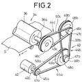
- the drive drum 36 can be rotated at a given speed by a belt transmission mechanism 40 according to the present invention.
- the belt transmission mechanism 40 comprises a first speed reducer 44a, a second speed reducer 44b, and a third speed reducer 44c which are operatively coupled between a rotational drive source 42 and the drive drum 36.
- the first speed reducer 44a comprises a first smaller-diameter drive pulley 46a mounted on a rotatable drive shaft 42a of the rotational drive source 42, a first larger-diameter driven pulley 48a spaced from the first smaller-diameter drive pulley 46a, and a first belt 50a trained around the first drive pulley 46a and the first driven pulley 48a.
- the second speed reducer 44b has a second smaller-diameter drive pulley 46b coaxially mounted on the first driven pulley 48a, a second larger-diameter driven pulley 48b spaced from the second smaller-diameter drive pulley 46b, and a second belt 50b trained around the second drive and driven pulleys 46b, 48b.
- the third speed reducer 44c has a third smaller-diameter drive pulley 46c coaxially mounted on the second driven pulley 48b, a third larger-diameter driven pulley 48c spaced from the third smaller-diameter drive pulley 46c, and a third belt 50c trained around the third drive and driven pulleys 46c, 48c.
- the second and third drive pulleys 46b, 46c are identical in structure to the first drive pulley 46a in that the second and third drive pulleys 46b, 46c have respective crowns 47b, 47c.
- the second and third driven pulleys 48b, 48c are identical in structure to the first driven pulley 48a in that the second and third driven pulleys 48b, 48c have respective crowns 49b, 49c.
- a pair of guide plates 52a, 52b is positioned on a feed path along which the film S is fed by the feed mechanism 34, and a cutter 54 comprising a pair of cutter blades for cutting off the film S into a predetermined length is disposed closely to the guide plates 52a, 52b.
- Two pairs of rollers 56, 58 are located downstream the cutter 54 along the feed path, the pair of rollers 58 being positioned near a film discharge slot 60 defined in a wall of the housing 12 remote from the lid 16.
- the film discharge slot 60 opens into a developing apparatus 62.
- the housing 12 accommodates therein a light beam scanner 70 disposed below the feed mechanism 34 for scanning the film S with a laser beam to record image information on the film S.
- the light beam scanner 70 has laser beam sources 72a, 72b for emitting a recording laser beam L1 and a synchronizing laser beam L2, respectively.
- the laser beam sources 72a, 72b are mounted on a reference plate 74 fixed to the housing 12.
- On the reference plate 74 there are disposed a mirror 76, a deflector 78 such as a galvanometer mirror, a scanning lens 80 such as an f ⁇ lens, and a mirror 82 jointly for scanning the film S with the recording laser beam L1 emitted from the laser beam source 72a.
- the synchronizing laser beam L2 emitted from the laser beam source 72b is guided toward a mirror 84 by the mirror 76, the galvanometer mirror 78, the scanning lens 80, and the mirror 82.
- the mirror 84 reflects the synchronizing laser beam L2 toward a reference grid plate 86 having a transmissive grid with a light guide bar 88 disposed closely behind the reference grid plate 86.
- Light detectors (not shown) are mounted on the respective opposite ends of the light guide bar 88 for detecting, as a pulse signal, the synchronizing laser beam L2 that has passed through the reference grid plate 86 and the light guide bar 88.
- the lid 14 is opened about the hinge 14 with respect to the housing 12, and the magazine 26 is loaded into the magazine loading assembly 20.
- the magazine 26 stores a roll of elongate unexposed film S therein, and an end of the film S is drawn through the film outlet slot 28 and gripped by the feed rollers 30.
- the lid 16 is closed, and the feed rollers 30 are rotated.
- the feed mechanism 34 and the feed rollers 30 are rotated in synchronism with each other while allowing the film S to sag to a certain extent between the feed mechanism 34 and the feed rollers 30.
- the rotational drive source 42 of the belt transmission mechanism 40 is energized to rotate the drive shaft 42a in the direction indicated by the arrow
- the first drive pulley 46a coupled to the drive shaft 42a is rotated in the same direction
- the first driven pulley 48a operatively connected to the first drive pulley 46a by the first belt 50a is rotated in the direction indicated by the arrow at a relatively low speed.
- the rotation from the first drive pulley 46a is transmitted to the drive drum 36 while being reduced in speed by the second drive pulley 46b, the second belt 50b, and the second driven pulley 48b of the second speed reducer 44b, and also by the third drive pulley 46c, the third belt 50c, and the third driven pulley 48c of the third speed reducer 44c. Therefore, the drive drum 36 is rotated at a considerably low speed in the direction indicated by the arrow for thereby feeding the film S gripped by the drive drum 36 and the nip rollers 38a, 38b in the auxiliary scanning direction indicated by the arrow X.
- the light beam scanner 70 is energized.
- the laser beam sources 72a, 72b are energized to emit respective laser beams L1, L2, which are reflected by the mirror 76 to the galvanometer mirror 78.
- the galvanometer mirror 78 as it swings back and forth deflects the laser beams L1, L2.
- the laser beam L1 travels through the scanning lens 80 and is reflected by the mirror 82 so as to be applied to and hence scan the film S between the nip rollers 38a, 38b.
- the laser beam L2 which is also reflected by the mirror 82 is reflected by the mirror 84, and passes the reference grid plate 86 into the light guide bar 88.
- the laser beam L2 is detected as a pulse signal by the light detectors on the respective opposite ends of the light guide bar 88.
- the pulse signal generated by the light detectors is frequency-multiplied into a synchronizing signal.
- the laser beam L1 scans the film S in the main scanning direction normal to the auxiliary scanning direction while at the same time the film S is being fed in the auxiliary scanning direction by the feed mechanism 34. Since the laser beam L1 is modulated by desired image information, the laser beam L1 records a two-dimensional image corresponding to the image information on the film S.
- the exposed film S is then guided by the guide plates 52a, 52b to travel along the feed path in the direction indicated by the arrow X, and delivered toward the film discharge slot 60 by the roller pairs 56, 58.
- the film S is cut to a desired length by the cutter 54.
- the cut film length is then discharged from the film discharge slot 60 and supplied into the developing apparatus 62.
- the developing apparatus 62 the image on the film length is developed into an original film plate, which may be used in any of various applications.
- D2/D1 k ⁇ R1/R2 (k ⁇ 1).
- This relationship of these diameters and radii is effective in causing the first belt 50a to elongate to substantially the same extent on the outer circumferential surfaces of the first drive and driven pulleys 46a, 48a, thereby reliably preventing the speed reduction ratio of the first speed reducer 44a from varying, even when the tension of the first belt 50a varies.
- the belt transmission mechanism 40 is relatively simple in overall structure and can be manufactured relatively inexpensively.
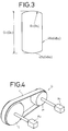
- the inventor experimentally determined the relationship between belt tensions and speed reduction ratios using differently dimensioned samples of a belt transmission mechanism G of different dimensions as shown in FIG. 4.
- the belt transmission mechanism G comprises a drive pulley H, a driven pulley I, and a belt J trained around the drive and driven pulleys H, I.
- Encoders K1, K2 are coupled respec tively to the drive and driven pulleys H, I.
- Any speed reduction ratio error should be limited to ⁇ 0.005 % or less, preferably ⁇ 0.0025 %, for the purpose of feeding the film S highly accurately in the auxiliary scanning direction.
Landscapes
- Engineering & Computer Science (AREA)
- General Engineering & Computer Science (AREA)
- Mechanical Engineering (AREA)
- Devices For Conveying Motion By Means Of Endless Flexible Members (AREA)
Applications Claiming Priority (2)
| Application Number | Priority Date | Filing Date | Title |
|---|---|---|---|
| JP158736/93 | 1993-06-29 | ||
| JP05158736A JP3083684B2 (ja) | 1993-06-29 | 1993-06-29 | ベルト伝動機構 |
Publications (2)
| Publication Number | Publication Date |
|---|---|
| EP0632214A1 true EP0632214A1 (de) | 1995-01-04 |
| EP0632214B1 EP0632214B1 (de) | 1997-01-15 |
Family
ID=15678215
Family Applications (1)
| Application Number | Title | Priority Date | Filing Date |
|---|---|---|---|
| EP94109823A Expired - Lifetime EP0632214B1 (de) | 1993-06-29 | 1994-06-24 | Riemengetriebe |
Country Status (4)
| Country | Link |
|---|---|
| US (1) | US5411444A (de) |
| EP (1) | EP0632214B1 (de) |
| JP (1) | JP3083684B2 (de) |
| DE (1) | DE69401465T2 (de) |
Cited By (2)
| Publication number | Priority date | Publication date | Assignee | Title |
|---|---|---|---|---|
| EP2045008A2 (de) | 2007-10-04 | 2009-04-08 | Evonik Degussa GmbH | Katalysator |
| WO2011104170A1 (en) | 2010-02-24 | 2011-09-01 | Evonik Degussa Gmbh | Thermally and mechanically stable precious metal-loaded catalysts |
Families Citing this family (17)
| Publication number | Priority date | Publication date | Assignee | Title |
|---|---|---|---|---|
| US5728252A (en) * | 1995-09-19 | 1998-03-17 | Polaroid Corporation | Method and apparatus for laminating image-bearing media |
| US6405833B1 (en) * | 2000-01-06 | 2002-06-18 | Otis Elevator Company | Flexible flat rope sheave assembly with separate shoulder and flange surfaces having varying friction properties |
| US6440019B1 (en) | 2000-08-17 | 2002-08-27 | The Boeing Company | Solar power system drive unit |
| US6672983B2 (en) | 2000-12-21 | 2004-01-06 | The Goodyear Tire & Rubber Company | Power transmission drive system |
| US6860500B2 (en) * | 2001-12-13 | 2005-03-01 | Fasst Company | Motorcycle handlebar with shock absorber |
| CN1997581B (zh) | 2004-08-04 | 2012-05-16 | 奥蒂斯电梯公司 | 升降机系统中采用的滑轮和组件 |
| JP4939190B2 (ja) * | 2006-11-30 | 2012-05-23 | 本田技研工業株式会社 | 小型車両用パワーユニット |
| DE102010050783A1 (de) * | 2010-11-10 | 2012-05-10 | Thyssenkrupp Presta Ag | Geräuscharmer Riementrieb |
| WO2014192438A1 (ja) * | 2013-05-28 | 2014-12-04 | 京セラドキュメントソリューションズ株式会社 | 金属ベルトおよび該金属ベルトを備える駆動機構 |
| JP5903412B2 (ja) * | 2013-08-08 | 2016-04-13 | 京セラドキュメントソリューションズ株式会社 | 駆動装置 |
| US9377097B2 (en) * | 2014-02-21 | 2016-06-28 | Kuhn North America, Inc. | Cartridge drive |
| JP2015191122A (ja) * | 2014-03-28 | 2015-11-02 | キヤノン株式会社 | 駆動伝達装置及び画像形成装置 |
| JP2017227844A (ja) * | 2016-06-24 | 2017-12-28 | キヤノン株式会社 | 動力伝達装置およびそれを備えた画像形成装置 |
| FR3090619B1 (fr) * | 2018-12-19 | 2021-01-01 | Saint Gobain Isover | Machine de fibrage à maintenance améliorée |
| JP7281069B2 (ja) * | 2019-01-08 | 2023-05-25 | 京セラドキュメントソリューションズ株式会社 | ベルト駆動装置、画像形成装置 |
| WO2021021577A1 (en) | 2019-07-26 | 2021-02-04 | Allied H2O, Inc. | Irrigation pumpjack |
| JP7472547B2 (ja) * | 2020-03-03 | 2024-04-23 | 京セラドキュメントソリューションズ株式会社 | 駆動伝達装置及び画像形成装置 |
Citations (2)
| Publication number | Priority date | Publication date | Assignee | Title |
|---|---|---|---|---|
| BE520967A (de) * | ||||
| JPH02118248A (ja) * | 1988-10-24 | 1990-05-02 | Fuji Photo Film Co Ltd | 金属ベルトの横ずれ防止構造 |
Family Cites Families (3)
| Publication number | Priority date | Publication date | Assignee | Title |
|---|---|---|---|---|
| US1290894A (en) * | 1916-11-21 | 1919-01-14 | Daniel R Bryan | Pulley and belting. |
| US3851535A (en) * | 1973-04-06 | 1974-12-03 | S Presentey | Special belt and pulley rim transmission device |
| DE68911794T2 (de) * | 1988-08-12 | 1994-07-07 | Bando Chemical Ind | Bandgetriebe und Riemenscheibe. |
-
1993
- 1993-06-29 JP JP05158736A patent/JP3083684B2/ja not_active Expired - Lifetime
-
1994
- 1994-06-24 DE DE69401465T patent/DE69401465T2/de not_active Expired - Fee Related
- 1994-06-24 EP EP94109823A patent/EP0632214B1/de not_active Expired - Lifetime
- 1994-06-29 US US08/267,234 patent/US5411444A/en not_active Expired - Lifetime
Patent Citations (2)
| Publication number | Priority date | Publication date | Assignee | Title |
|---|---|---|---|---|
| BE520967A (de) * | ||||
| JPH02118248A (ja) * | 1988-10-24 | 1990-05-02 | Fuji Photo Film Co Ltd | 金属ベルトの横ずれ防止構造 |
Non-Patent Citations (1)
| Title |
|---|
| PATENT ABSTRACTS OF JAPAN vol. 14, no. 339 (M - 1001) 23 July 1990 (1990-07-23) * |
Cited By (3)
| Publication number | Priority date | Publication date | Assignee | Title |
|---|---|---|---|---|
| EP2045008A2 (de) | 2007-10-04 | 2009-04-08 | Evonik Degussa GmbH | Katalysator |
| DE102007047430A1 (de) | 2007-10-04 | 2009-04-09 | Evonik Degussa Gmbh | Katalysator |
| WO2011104170A1 (en) | 2010-02-24 | 2011-09-01 | Evonik Degussa Gmbh | Thermally and mechanically stable precious metal-loaded catalysts |
Also Published As
| Publication number | Publication date |
|---|---|
| DE69401465D1 (de) | 1997-02-27 |
| EP0632214B1 (de) | 1997-01-15 |
| JP3083684B2 (ja) | 2000-09-04 |
| US5411444A (en) | 1995-05-02 |
| JPH0712186A (ja) | 1995-01-17 |
| DE69401465T2 (de) | 1997-04-30 |
Similar Documents
| Publication | Publication Date | Title |
|---|---|---|
| EP0632214B1 (de) | Riemengetriebe | |
| US5280368A (en) | Fixed full width array scan head calibration apparatus | |
| US4595957A (en) | Optical light bead scanning arrangement | |
| US4967233A (en) | Fixed full width array scan head calibration apparatus | |
| JPS6292572A (ja) | 光ビ−ム走査装置 | |
| US4896809A (en) | Feed device | |
| US5181715A (en) | Sheet conveying unit and system using the same | |
| EP0311821B1 (de) | Vorrichtung zum Transportieren von Dokumenten | |
| US4605971A (en) | Document reading device | |
| US6788435B2 (en) | Image reader for use in image forming apparatus | |
| EP0554476A1 (de) | Verfahren und Vorrichtung zum Abtasten und Digitalisieren | |
| US6384896B1 (en) | Microfilm search device | |
| US4694163A (en) | Apparatus for scanning sheet-shaped recording medium with a bending roller | |
| JPS63258339A (ja) | 副走査搬送機構 | |
| JPH0443469B2 (de) | ||
| JP3517472B2 (ja) | プリント用ヘッド装置 | |
| US4854672A (en) | Optical system for copier | |
| JPS62244837A (ja) | 光ビ−ム走査装置 | |
| JPS63258340A (ja) | シ−ト体搬送機構 | |
| JPH07303168A (ja) | シート搬送機構及び画像走査装置 | |
| JPH09267949A (ja) | 画像記録装置 | |
| JPH03227847A (ja) | 記録装置 | |
| US2206367A (en) | Soundhead | |
| JPH06312850A (ja) | 情報記録カードの駆動装置 | |
| JPH0667315A (ja) | 原稿走査装置 |
Legal Events
| Date | Code | Title | Description |
|---|---|---|---|
| PUAI | Public reference made under article 153(3) epc to a published international application that has entered the european phase |
Free format text: ORIGINAL CODE: 0009012 |
|
| AK | Designated contracting states |
Kind code of ref document: A1 Designated state(s): DE FR GB |
|
| 17P | Request for examination filed |
Effective date: 19950626 |
|
| GRAG | Despatch of communication of intention to grant |
Free format text: ORIGINAL CODE: EPIDOS AGRA |
|
| 17Q | First examination report despatched |
Effective date: 19960417 |
|
| GRAH | Despatch of communication of intention to grant a patent |
Free format text: ORIGINAL CODE: EPIDOS IGRA |
|
| GRAH | Despatch of communication of intention to grant a patent |
Free format text: ORIGINAL CODE: EPIDOS IGRA |
|
| GRAA | (expected) grant |
Free format text: ORIGINAL CODE: 0009210 |
|
| AK | Designated contracting states |
Kind code of ref document: B1 Designated state(s): DE FR GB |
|
| REF | Corresponds to: |
Ref document number: 69401465 Country of ref document: DE Date of ref document: 19970227 |
|
| ET | Fr: translation filed | ||
| PLBE | No opposition filed within time limit |
Free format text: ORIGINAL CODE: 0009261 |
|
| STAA | Information on the status of an ep patent application or granted ep patent |
Free format text: STATUS: NO OPPOSITION FILED WITHIN TIME LIMIT |
|
| 26N | No opposition filed | ||
| REG | Reference to a national code |
Ref country code: GB Ref legal event code: IF02 |
|
| REG | Reference to a national code |
Ref country code: GB Ref legal event code: 732E |
|
| REG | Reference to a national code |
Ref country code: FR Ref legal event code: TP Ref country code: FR Ref legal event code: CD |
|
| PGFP | Annual fee paid to national office [announced via postgrant information from national office to epo] |
Ref country code: FR Payment date: 20080617 Year of fee payment: 15 |
|
| PGFP | Annual fee paid to national office [announced via postgrant information from national office to epo] |
Ref country code: GB Payment date: 20090624 Year of fee payment: 16 Ref country code: DE Payment date: 20090529 Year of fee payment: 16 |
|
| GBPC | Gb: european patent ceased through non-payment of renewal fee |
Effective date: 20100624 |
|
| REG | Reference to a national code |
Ref country code: FR Ref legal event code: ST Effective date: 20110228 |
|
| PG25 | Lapsed in a contracting state [announced via postgrant information from national office to epo] |
Ref country code: DE Free format text: LAPSE BECAUSE OF NON-PAYMENT OF DUE FEES Effective date: 20110101 |
|
| PG25 | Lapsed in a contracting state [announced via postgrant information from national office to epo] |
Ref country code: FR Free format text: LAPSE BECAUSE OF NON-PAYMENT OF DUE FEES Effective date: 20100630 |
|
| PG25 | Lapsed in a contracting state [announced via postgrant information from national office to epo] |
Ref country code: GB Free format text: LAPSE BECAUSE OF NON-PAYMENT OF DUE FEES Effective date: 20100624 |