EP0632255A1 - Procédé de contrôle du rendement de dosage dans un dosomètre à taux d'allègement - Google Patents
Procédé de contrôle du rendement de dosage dans un dosomètre à taux d'allègement Download PDFInfo
- Publication number
- EP0632255A1 EP0632255A1 EP93110539A EP93110539A EP0632255A1 EP 0632255 A1 EP0632255 A1 EP 0632255A1 EP 93110539 A EP93110539 A EP 93110539A EP 93110539 A EP93110539 A EP 93110539A EP 0632255 A1 EP0632255 A1 EP 0632255A1
- Authority
- EP
- European Patent Office
- Prior art keywords
- metering
- dosing
- value
- level
- dlp
- Prior art date
- Legal status (The legal status is an assumption and is not a legal conclusion. Google has not performed a legal analysis and makes no representation as to the accuracy of the status listed.)
- Granted
Links
- 238000000034 method Methods 0.000 title claims abstract description 28
- 238000010606 normalization Methods 0.000 claims description 13
- 238000005259 measurement Methods 0.000 claims description 5
- 230000001419 dependent effect Effects 0.000 claims description 4
- 239000000463 material Substances 0.000 claims description 4
- 238000013213 extrapolation Methods 0.000 claims description 3
- 239000013590 bulk material Substances 0.000 abstract description 12
- 238000010586 diagram Methods 0.000 description 7
- 239000000047 product Substances 0.000 description 3
- 238000012544 monitoring process Methods 0.000 description 2
- 230000033228 biological regulation Effects 0.000 description 1
- 230000001276 controlling effect Effects 0.000 description 1
- 238000012886 linear function Methods 0.000 description 1
- 230000001105 regulatory effect Effects 0.000 description 1
- 239000013589 supplement Substances 0.000 description 1
- 238000005303 weighing Methods 0.000 description 1
Images


Classifications
-
- G—PHYSICS
- G05—CONTROLLING; REGULATING
- G05D—SYSTEMS FOR CONTROLLING OR REGULATING NON-ELECTRIC VARIABLES
- G05D7/00—Control of flow
- G05D7/06—Control of flow characterised by the use of electric means
- G05D7/0605—Control of flow characterised by the use of electric means specially adapted for solid materials
-
- G—PHYSICS
- G01—MEASURING; TESTING
- G01G—WEIGHING
- G01G11/00—Apparatus for weighing a continuous stream of material during flow; Conveyor belt weighers
- G01G11/08—Apparatus for weighing a continuous stream of material during flow; Conveyor belt weighers having means for controlling the rate of feed or discharge
- G01G11/086—Apparatus for weighing a continuous stream of material during flow; Conveyor belt weighers having means for controlling the rate of feed or discharge of the loss-in-weight feeding type
Definitions
- the invention relates to a method for controlling the metering capacity of a differential metering scale according to the preamble of claim 1.
- Differential dosing scales are used for the exact dosing of materials, especially bulk goods.
- the dosing rate i.e. the amount of material dispensed per unit of time, for example bulk material, is determined by continuously weighing the bulk material in the container of the differential metering weigher and determining the change in mass per unit of time.
- differential metering scales In order to be able to maintain the desired metering capacity as precisely as possible, differential metering scales have a corresponding metering control, whereby the actual metering capacity is continuously measured, compared with the target metering capacity and, in the event of a deviation, an actuating signal is emitted which indicates the conveying speed of the metering element, e.g. the speed of a Screw conveyor, influenced accordingly.
- control mode is preferably switched to control mode, the conveying speed of the metering element being set according to a predetermined scheme.
- This known method delivers satisfactory results if the same dosing performance as during the preceding emptying phase is to be present during the refilling phase.
- this known method cannot achieve a satisfactory accuracy of the metering capacity because the manipulated values have to be of different sizes due to the different target metering capacity.
- the invention is therefore based on the object of providing a control method of the type mentioned in the preamble of claim 1, which enables improved metering accuracy in the control mode in a simple manner, in particular even when the target metering power is changed.
- a device- and product-specific metering performance profile is first measured and stored or manually entered into the metering control, which consists of different actual metering values and the actuating signal values required to achieve these actual metering values, the respective container level being recorded as an additional parameter.
- a fill level compensation characteristic is measured and stored or manually entered into the dosing control, which is used to maintain one or more constant Dosing rates required control signal values depending on different container levels.
- these two characteristics i.e. the metering performance profile and the filling level compensation characteristic are connected to one another by first determining the difference value between the actuating signal value that is assigned to the container level of the metering performance profile stored as a parameter in the filling level compensation characteristic and that actuating signal that is assigned to an actual container level.
- the conveying speed is then controlled with such a control signal value, which is assigned a predeterminable metering capacity on the basis of the metering capacity profile and is corrected by the difference value determined from the level compensation characteristic.
- the metering performance profile is also taken into account, so that level compensation during control operation is possible not only with constant, but also with changing target metering rates.
- the level compensation characteristic can either be entered manually or determined automatically. This takes place at a constant dosing rate. If the target dosing capacity should differ from this constant dosing capacity in later control operation, this deviation can be taken into account by determining the dependency of the level compensation curve on the respective capacities. This results in a correction function for the difference values mentioned above.
- a correction function can be a linear function, for example.
- the control signal difference value is advantageously modified by means of a correction factor, which consists of the ratio of a certain metering rate to that constant metering rate at which the level compensation characteristic was determined.
- control signal differential values for correcting the control signal value are determined from the level compensation characteristic in order to be able to take into account different container levels.
- the respective control signal difference value can be determined in a single step by comparing the container level on which the metering performance profile is based with the actual container level or the assigned control signal values.
- the actuating signal difference value in two steps. This is advantageously done by first normalizing the metering performance profile determined at different container levels to a constant normalizing container level by means of normalization correction values obtained from the level compensation characteristic.
- the normalization correction value forms a first part of the control signal difference value.
- a residual correction value for the correction of the actuating signal is then determined on the basis of the normalized metering power profile from the fill level compensation characteristic, which together with the corresponding normalization correction value gives the entire difference value for correcting the actuating signal.
- the residual correction value is determined from the difference between that control signal value that is assigned to the normalization container level and that control signal value that is assigned to an actual container level.
- the object is achieved by the features of claim 4.
- This alternative embodiment differs from of the embodiment according to claim 1 only in that metering capacity / container level values are determined for the level compensation characteristic at one or more constant control signal values and not control signal / container level values at one or more constant metering capacities.
- the fill level compensation curve of the alternative embodiment thus indicates the change in the actual metering output as a function of different container levels at a constant control signal value. From this filling level compensation characteristic, a dosing performance difference value is determined, which is used to correct the dosing performance profile and thus to correct the control signal value for a predetermined target dosing performance.
- the bulk density of the material to be dosed is advantageously stored as an additional parameter in the dosing performance profile and used to correct the control signal value.
- three to ten, in particular six, preferably regularly spaced, actual dosing performance values and the actuating signal values required to achieve these actual dosing performance values are advantageously stored and further, in particular intermediate values are determined by, in particular linear, interpolation or extrapolation. This enables a quick determination of the dosing performance profile and a small memory requirement.
- At least one theoretical operating point which is determined from the metering performance profile and the filling level compensation characteristic and is determined from the predeterminable metering performance, the corrected actuating signal value associated therewith and the container level, is compared with at least one operating point measured during control operation, the consists of the measured actual dosing capacity, the actual control signal value of the controller and the measured tank level.
- a correction value taking into account the deviation of the theoretical from the measured working point for the further correction of the theoretical actuating signal value for the control operation is then formed and / or an alarm is issued if the deviation of the theoretical working point from the measured working point exceeds a predeterminable maximum value.
- the theoretical working point can be adapted to changing product properties, for example changing bulk density, by constant measurement and comparison between the theoretical and the actual working point. This is done, for example, by continuously comparing the actually determined actuating signal value for the measured actual metering output with the theoretical actuating signal value that should be calculated by the machine control system for this actual metering output, whereupon the ratio of the actual actuating signal value / theoretical actuating signal value a correction constant for the dosing performance profile is calculated. This adjustment of the theoretical operating point leads to a further increase in dosing accuracy during control operation.
- the monitoring of the deviation between the theoretical and the measured operating point which is provided as a supplement or as an alternative to this, has its significance in that, for example, leaks in the refilling flap of a container filling device and associated inaccuracies can be discovered during the control operation. If the product trickles into the container due to a leaky refill flap, the dosage is too high without such monitoring, since the weight in the container does not decrease in accordance with the actual metering performance and the differential metering scale adjusts accordingly. With By means of the comparison between the theoretical and the actual working point, taking into account both the dosing performance profile and the filling level compensation characteristic, an excessive shift in the actual working point can be determined.
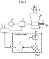
- FIG. 1 shows a differential dosing scale with a container 1, to which bulk material can be fed via a filling shaft 2 of a filling device.
- a flap 3 inside the feed chute 2 regulates the supply of the bulk material.
- the bulk material is discharged from the container 1 by means of a metering device in the form of a metering screw 4 with a predeterminable metering rate.
- a metering device in the form of a metering screw 4 with a predeterminable metering rate.
- the weight of the bulk material within the container 1 is continuously measured by means of a scale 5 and the change in weight per unit time is calculated in a differentiator 6 of a metering control.
- This actual metering power is compared with a predefinable target metering power ⁇ target by means of a comparison element 7 and the deviation is fed to a PID controller 8, which outputs a corresponding control signal value N to a motor controller 9.
- the motor controller 9 compares the control signal value N with the actual speed value of the metering screw 4 or the motor 11, which is output by a tachometer 10 of a drive motor 11, and, if necessary, outputs a corresponding control signal to the motor 11 to increase or decrease the metering screw speed in order to match the actual metering power to bring the target dosing performance into agreement.
- this control mode is switched to a control mode during the start phase, the refilling phase, when the set metering power is changed and during a fault locking phase, in order to avoid inaccurate metering.
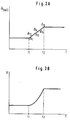
- control mode it may be desirable to change the target metering rate according to a predetermined scheme.
- a predetermined scheme for example, as can be seen from Fig. 2A, a constant increase in the target metering rate between times t1 and t2, the target metering rates ⁇ 1 to ⁇ 6 to be achieved.
- control signal values N required to achieve such metering output values are shown schematically in FIG. 2B. If a metering power profile described below is not linear, the course of the control signal values as a function of time is also not linear in order to achieve a linear ramp according to FIG. 2A, for example.
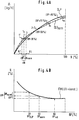
- FIG. 3A shows the dosing performance profile DLP in the form of a diagram, the actual dosing performance ⁇ being plotted on the ordinate and the desired control signal values N desired as a percentage of the maximum desired control signal value on the abscissa.
- the curve which is non-linear in the present case, but which can also have other, for example, linear forms, indicates which actuating signal values, that is to say speeds, are required in order to obtain corresponding actual metering capacities for a specific differential weigher and a specific bulk material.
- a metering capacity that does not increase proportionally to the speed results in particular from the fact that with certain screw metering devices the metering screw is no longer properly filled with increasing speed.
- the dosing performance profile DLP is expediently determined by, for example, measuring the required speeds for four different dosing performances and either automatically storing the corresponding values in the dosing control or entering them manually in the dosing control. These values are represented by points 1-4 in Fig. 3A. In addition, the associated container levels BP are saved or entered, at which these values have been reached.
- the individual measuring points 1 - 4 of the dosing performance profile DLP are arithmetically connected to one another by the dosing control, for example by linear interpolation. In the case of a linear interpolation, the dosing performance profile DLP does not consist of a continuous curve, as shown, but of a series of individual lines with possibly different slopes.
- a fill level compensation characteristic shown in FIG. 3B is stored in the dosing control.
- the filling level compensation characteristic which in the present case is non-linear, but can also have other, for example linear, forms, indicates which control signal values N should be required in order to maintain constant metering rates ⁇ at different container levels BP.
- the fill level compensation characteristic according to FIG. 3B is expediently determined by measuring, for example, five control signal values at constant metering power and the associated container level BP during a previous control operation. The values can then either be entered manually into the dosing control or saved automatically. The filling level compensation curve is automatically calculated from these values by the dosing control.
- This measuring point i.e. the metering capacity ⁇ 1 and the control signal value N1 was determined and stored at a container level of 30%. If now in control mode with specification of the metering output ⁇ 1 the container level is not 30% but, for example, 80%, those control signal values are first determined from the level compensation characteristic of FIG. 3B, which are assigned to container levels of 30% and 80%. The difference between these two control signal values results in the control signal difference value ⁇ N.
- the control signal value N 1 of the metering performance profile DLP is corrected accordingly, so that a corrected control value N'1 is obtained with which the conveying speed of the metering device is controlled.
- control signal values N for other points in the metering performance profile are corrected in a corresponding manner.
- control signal difference values ⁇ N could be determined for different dosing capacities be that a separate level compensation characteristic is recorded and stored for each conceivable metering capacity, as shown in FIG. 5. However, this would require too much computing and storage effort.
- Different metering capacities are therefore expediently taken into account in the filling level compensation characteristic in that a single or a few filling level compensation curves are recorded and stored and different metering capacities are taken into account by means of a correction function.
- This correction function can consist in the fact that a correction factor is formed from the ratio of a certain dosing performance to that dosing performance at which the filling level compensation characteristic was recorded.
- Such a correction factor is based on the mostly correct assumption that the actuating signal difference value ⁇ N is proportional to the metering capacity.
- the dosing performance profile characterized by these measuring points and recorded at different container levels is initially standardized to a uniform container level.
- This normalization container level BP norm should be 50% in the example shown.
- the metering performance profile is normalized to the normalizing container level in the same way as the correction of the actuating signal difference value, as has been described with reference to FIGS. 3A and 3B. Representative of measuring points 2, 3 and 4 of FIG. 4A, this is described below with reference to measuring point 1. Measuring point 1 of FIG. 4A was recorded at a container level of 30%, so that first of all the control signal value N which is assigned to the container level of 30% is determined from the filling level compensation characteristic of FIG. 4B. Then the actuating value that is assigned to the normalization tank level BP norm of 50% is determined from the level compensation characteristic FHK. The difference between the two manipulated values is designated ⁇ N norm in FIG. 4B. The correction of the measuring point 1 of the dosing performance profile DLP from FIG. 4A by means of the normalizing difference value ⁇ N norm gives the point 1 n .
- the intermediate step due to the normalization of the dosing performance profile is advantageous when determining the actuating signal difference value ⁇ N, since this means that different measuring points of the dosing performance profile, i.e. For different dosing capacities, a fixed comparison tank level is created, with which tank levels that deviate therefrom can be compared in the later control mode.
- the bulk density can also be saved as a parameter. This enables the difference values .DELTA.N to be additionally corrected for correcting the control signal values by means of a bulk density correction factor.
- FIG. 6A shows a dosing performance profile DLP which corresponds to the dosing performance profile of FIG. 4A.
- the N / BP fill level compensation characteristic described with reference to FIG. 4B is not used to correct the control signal values, but a ⁇ / BP fill level compensation characteristic FHK shown in FIG. 6B.
- This level compensation characteristic indicates how the actual dosing capacity changes depending on different container levels with a constant control signal value.
- a metering performance difference value ⁇ _ is first determined from the level compensation characteristic of FIG. 6B. This difference value determination is carried out in the same way as the determination of the actuating signal difference value ⁇ N from FIG. 3B or ⁇ N norm , ⁇ N 'from FIG. 4B.
- the dosing rate difference value ⁇ leads to a correction of point 1 in the dosing rate profile of FIG. 6A, whereby point 1 is obtained corr .
- a corresponding correction of points 3 and 4 of the metering performance profile DLP leads to points 3 corr and 4 corr , which together with points 1 corr and 2 determine a corrected metering performance profile DLP corr . Because the corrected Dosier ancientsprofils can now for a particular desired dosing rate, for example m to in Fig. 6A, the corrected set value N to be determined.
- dosing rate difference values ⁇ are used for the correction of the dosing rate profile DLP not only a single, but different dosing rate difference values ⁇ are used.
- the respective difference value depends in particular on the shape of the fill level compensation curve, the container level at which the points of the dosing performance profile DLP to be corrected were determined, and on the control signal value N at which the fill level compensation curve was recorded. It is also based on the 6A and 6B possible alternative embodiment possible to correct the control signal value N either in a one-stage or in a two-stage method according to the explanations for FIGS. 3A, 3B and 4A, 4B.
- the metering power difference value ⁇ can also be corrected in the same way as the actuating signal difference value ⁇ N by means of an additional correction factor, which results from the ratio of a specific actuating signal value to that actuating signal value at which the level compensation characteristic was recorded.
Landscapes
- Physics & Mathematics (AREA)
- General Physics & Mathematics (AREA)
- Engineering & Computer Science (AREA)
- Automation & Control Theory (AREA)
- Weight Measurement For Supplying Or Discharging Of Specified Amounts Of Material (AREA)
- Filling Or Emptying Of Bunkers, Hoppers, And Tanks (AREA)
- Treating Waste Gases (AREA)
Priority Applications (4)
| Application Number | Priority Date | Filing Date | Title |
|---|---|---|---|
| EP93110539A EP0632255B1 (fr) | 1993-07-01 | 1993-07-01 | Procédés de commande du taux d'alimentation dans un dosomètre différentiel |
| AT93110539T ATE153444T1 (de) | 1993-07-01 | 1993-07-01 | Verfahren zur steuerung der dosierleistung einer differentialdosierwaage |
| DE59306533T DE59306533D1 (de) | 1993-07-01 | 1993-07-01 | Verfahren zur Steuerung der Dosierleistung einer Differentialdosierwaage |
| JP6151279A JPH07139990A (ja) | 1993-07-01 | 1994-07-01 | 差動調量秤の調量能力の調整方法 |
Applications Claiming Priority (1)
| Application Number | Priority Date | Filing Date | Title |
|---|---|---|---|
| EP93110539A EP0632255B1 (fr) | 1993-07-01 | 1993-07-01 | Procédés de commande du taux d'alimentation dans un dosomètre différentiel |
Publications (2)
| Publication Number | Publication Date |
|---|---|
| EP0632255A1 true EP0632255A1 (fr) | 1995-01-04 |
| EP0632255B1 EP0632255B1 (fr) | 1997-05-21 |
Family
ID=8213034
Family Applications (1)
| Application Number | Title | Priority Date | Filing Date |
|---|---|---|---|
| EP93110539A Expired - Lifetime EP0632255B1 (fr) | 1993-07-01 | 1993-07-01 | Procédés de commande du taux d'alimentation dans un dosomètre différentiel |
Country Status (4)
| Country | Link |
|---|---|
| EP (1) | EP0632255B1 (fr) |
| JP (1) | JPH07139990A (fr) |
| AT (1) | ATE153444T1 (fr) |
| DE (1) | DE59306533D1 (fr) |
Cited By (6)
| Publication number | Priority date | Publication date | Assignee | Title |
|---|---|---|---|---|
| EP1225429A1 (fr) * | 2001-01-17 | 2002-07-24 | PAVAN S.p.A. | Procédé de dosage pour substances et appareil de dosage correspondant |
| WO2008000405A3 (fr) * | 2006-06-27 | 2008-02-14 | Helmut Roppelt | Procédé et dispositif permettant de tester un filtre à particules pour un moteur à combustion interne |
| CN112473548A (zh) * | 2020-11-19 | 2021-03-12 | 三一石油智能装备有限公司 | 一种混配车粉料输送计量的控制方法、控制装置及混配车 |
| CN113196019A (zh) * | 2018-09-07 | 2021-07-30 | 克特朗技术公司 | 用于对用于倾注物料的配量设备在其储存容器的再填充期间进行重力调节的方法及用于实施该方法的配量设备 |
| CN115468638A (zh) * | 2022-09-02 | 2022-12-13 | 中国矿业大学 | 一种减少失重秤用螺旋输送物料出料波动方法和系统 |
| EP4209858A1 (fr) * | 2022-01-07 | 2023-07-12 | Kikusui Seisakusho Ltd. | Dispositif d'alimentation en poudre |
Families Citing this family (1)
| Publication number | Priority date | Publication date | Assignee | Title |
|---|---|---|---|---|
| WO2011021994A1 (fr) | 2009-08-17 | 2011-02-24 | Fluor Technologies Corporation | Dispositifs et procédés dajout d'ingrédient à perte de poids |
Citations (5)
| Publication number | Priority date | Publication date | Assignee | Title |
|---|---|---|---|---|
| DE2658252A1 (de) * | 1976-04-19 | 1977-11-03 | Acrison Inc | Wiege-zufuhrsystem |
| DE2754527A1 (de) * | 1976-12-07 | 1978-06-15 | Acrison Inc | Waege-beschickungsvorrichtung |
| DE3300911A1 (de) * | 1982-01-28 | 1983-08-18 | K-Tron International, Inc., 85258 Scottsdale, Ariz. | Verfahren zur verbesserung der zufuehrgenauigkeit eines materialzufuehrungssystems sowie einrichtung zur durchfuehrung des verfahrens |
| EP0291553A1 (fr) * | 1987-05-21 | 1988-11-23 | Carl Schenck Ag | Méthode pour régler une balance de dosage différentielle, en particulier pour matériaux en vrac, et une balance de dosage différentielle pour l'application de la méthode |
| EP0425735A1 (fr) * | 1989-10-30 | 1991-05-08 | Brabender Technologie Kg | Dispositif de dosage par poids pour matière coulante |
-
1993
- 1993-07-01 DE DE59306533T patent/DE59306533D1/de not_active Expired - Fee Related
- 1993-07-01 EP EP93110539A patent/EP0632255B1/fr not_active Expired - Lifetime
- 1993-07-01 AT AT93110539T patent/ATE153444T1/de not_active IP Right Cessation
-
1994
- 1994-07-01 JP JP6151279A patent/JPH07139990A/ja active Pending
Patent Citations (5)
| Publication number | Priority date | Publication date | Assignee | Title |
|---|---|---|---|---|
| DE2658252A1 (de) * | 1976-04-19 | 1977-11-03 | Acrison Inc | Wiege-zufuhrsystem |
| DE2754527A1 (de) * | 1976-12-07 | 1978-06-15 | Acrison Inc | Waege-beschickungsvorrichtung |
| DE3300911A1 (de) * | 1982-01-28 | 1983-08-18 | K-Tron International, Inc., 85258 Scottsdale, Ariz. | Verfahren zur verbesserung der zufuehrgenauigkeit eines materialzufuehrungssystems sowie einrichtung zur durchfuehrung des verfahrens |
| EP0291553A1 (fr) * | 1987-05-21 | 1988-11-23 | Carl Schenck Ag | Méthode pour régler une balance de dosage différentielle, en particulier pour matériaux en vrac, et une balance de dosage différentielle pour l'application de la méthode |
| EP0425735A1 (fr) * | 1989-10-30 | 1991-05-08 | Brabender Technologie Kg | Dispositif de dosage par poids pour matière coulante |
Cited By (9)
| Publication number | Priority date | Publication date | Assignee | Title |
|---|---|---|---|---|
| EP1225429A1 (fr) * | 2001-01-17 | 2002-07-24 | PAVAN S.p.A. | Procédé de dosage pour substances et appareil de dosage correspondant |
| WO2008000405A3 (fr) * | 2006-06-27 | 2008-02-14 | Helmut Roppelt | Procédé et dispositif permettant de tester un filtre à particules pour un moteur à combustion interne |
| US7882724B2 (en) | 2006-06-27 | 2011-02-08 | Helmut Roppelt | Method and configuration for testing a particle filter for an internal combustion engine |
| CN113196019A (zh) * | 2018-09-07 | 2021-07-30 | 克特朗技术公司 | 用于对用于倾注物料的配量设备在其储存容器的再填充期间进行重力调节的方法及用于实施该方法的配量设备 |
| CN113196019B (zh) * | 2018-09-07 | 2024-02-02 | 克特朗技术公司 | 用于对用于倾注物料的配量设备在其储存容器的再填充期间进行重力调节的方法及用于实施该方法的配量设备 |
| CN112473548A (zh) * | 2020-11-19 | 2021-03-12 | 三一石油智能装备有限公司 | 一种混配车粉料输送计量的控制方法、控制装置及混配车 |
| EP4209858A1 (fr) * | 2022-01-07 | 2023-07-12 | Kikusui Seisakusho Ltd. | Dispositif d'alimentation en poudre |
| US12318966B2 (en) | 2022-01-07 | 2025-06-03 | Kikusui Seisakusho Ltd. | Powdery-material feeding device |
| CN115468638A (zh) * | 2022-09-02 | 2022-12-13 | 中国矿业大学 | 一种减少失重秤用螺旋输送物料出料波动方法和系统 |
Also Published As
| Publication number | Publication date |
|---|---|
| DE59306533D1 (de) | 1997-06-26 |
| JPH07139990A (ja) | 1995-06-02 |
| ATE153444T1 (de) | 1997-06-15 |
| EP0632255B1 (fr) | 1997-05-21 |
Similar Documents
| Publication | Publication Date | Title |
|---|---|---|
| DE2754527C2 (fr) | ||
| DE3721186C2 (fr) | ||
| DE19622637B4 (de) | Verfahren und Regelungssystem für eine Motordrehzahl mit veränderlicher Regelabweichung | |
| DE3706708C2 (fr) | ||
| EP3847426B1 (fr) | Procédé pour la régulation gravimétrique d'un doseur pour un produit en vrac pendant le remplissage du réservoir de stockage de celui-ci et doseur pour la mise en oeuvre du procédé | |
| DE3618337A1 (de) | Adaptive elektrische kontroll- und regeleinrichtung | |
| DE60013835T2 (de) | Verfahren zum befüllen eines behälters | |
| DE4141256C2 (de) | Verfahren zur Korrektur der dynamischen Unwucht eines drehbaren Körpers und Vorrichtung zur Durchführung des Verfahrens | |
| DE60313833T2 (de) | Bodenverarbeitungsmaschine | |
| DE1558551B2 (de) | Vorrichtung zum beschicken eines hochofens mit automatisch zugeteilten komponenten | |
| EP0291553B1 (fr) | Méthode pour régler une balance de dosage différentielle, en particulier pour matériaux en vrac, et une balance de dosage différentielle pour l'application de la méthode | |
| EP0632255B1 (fr) | Procédés de commande du taux d'alimentation dans un dosomètre différentiel | |
| DE2216143C3 (de) | Verfahren und Vorrichtungen zum gewichtsgenauen Abmessen von Gütern | |
| DE1277811B (de) | Verfahren und Vorrichtung zur Konstanthaltung der Zusammensetzung des Kopf- oder Bodenprodukts in einer Fraktionierkolonne | |
| DE3910028A1 (de) | Verfahren und vorrichtung zur masseflussregelung eines gefoerderten materials | |
| DE3152398C2 (de) | Vorrichtung zum Zusammenstellen von Artikeln | |
| DE4442834C2 (de) | Verfahren zur Ermittlung des Optimalwertes eines Verstärkungsfaktors eines Regelungssystems | |
| DE3517475C2 (fr) | ||
| DE2658252C2 (fr) | ||
| DE1803372A1 (de) | Verfahren und Vorrichtung zum Messen physikalischer Eigenschaften | |
| DE102010009753B4 (de) | Vorrichtung und Verfahren zur Dosierregelung von Schüttgut | |
| DE2903259A1 (de) | Verfahren zum dosieren von materialien mit wechselnden fliesseigenschaften | |
| DE1498988A1 (de) | Verfahren und Vorrichtung zum Messen des Feuchtigkeitsgehalts koernigen Materials | |
| DE2741510A1 (de) | Verfahren und regelanordnung zur durchsatzregelung einer sichterumlaufmahlanlage | |
| EP1181507B1 (fr) | Dispositif de regulation pour doseur a vis sans fin |
Legal Events
| Date | Code | Title | Description |
|---|---|---|---|
| PUAI | Public reference made under article 153(3) epc to a published international application that has entered the european phase |
Free format text: ORIGINAL CODE: 0009012 |
|
| AK | Designated contracting states |
Kind code of ref document: A1 Designated state(s): AT BE CH DE DK ES FR GB IE IT LI LU NL PT |
|
| 17P | Request for examination filed |
Effective date: 19950623 |
|
| GRAG | Despatch of communication of intention to grant |
Free format text: ORIGINAL CODE: EPIDOS AGRA |
|
| 17Q | First examination report despatched |
Effective date: 19960719 |
|
| GRAH | Despatch of communication of intention to grant a patent |
Free format text: ORIGINAL CODE: EPIDOS IGRA |
|
| GRAH | Despatch of communication of intention to grant a patent |
Free format text: ORIGINAL CODE: EPIDOS IGRA |
|
| GRAA | (expected) grant |
Free format text: ORIGINAL CODE: 0009210 |
|
| AK | Designated contracting states |
Kind code of ref document: B1 Designated state(s): AT BE CH DE DK ES FR GB IE IT LI LU NL PT |
|
| PG25 | Lapsed in a contracting state [announced via postgrant information from national office to epo] |
Ref country code: NL Free format text: LAPSE BECAUSE OF FAILURE TO SUBMIT A TRANSLATION OF THE DESCRIPTION OR TO PAY THE FEE WITHIN THE PRESCRIBED TIME-LIMIT Effective date: 19970521 Ref country code: IT Free format text: LAPSE BECAUSE OF FAILURE TO SUBMIT A TRANSLATION OF THE DESCRIPTION OR TO PAY THE FEE WITHIN THE PRESCRIBED TIME-LIMIT;WARNING: LAPSES OF ITALIAN PATENTS WITH EFFECTIVE DATE BEFORE 2007 MAY HAVE OCCURRED AT ANY TIME BEFORE 2007. THE CORRECT EFFECTIVE DATE MAY BE DIFFERENT FROM THE ONE RECORDED. Effective date: 19970521 Ref country code: GB Effective date: 19970521 Ref country code: FR Effective date: 19970521 Ref country code: ES Free format text: THE PATENT HAS BEEN ANNULLED BY A DECISION OF A NATIONAL AUTHORITY Effective date: 19970521 Ref country code: DK Effective date: 19970521 |
|
| REF | Corresponds to: |
Ref document number: 153444 Country of ref document: AT Date of ref document: 19970615 Kind code of ref document: T |
|
| REG | Reference to a national code |
Ref country code: CH Ref legal event code: EP |
|
| REF | Corresponds to: |
Ref document number: 59306533 Country of ref document: DE Date of ref document: 19970626 |
|
| PG25 | Lapsed in a contracting state [announced via postgrant information from national office to epo] |
Ref country code: LU Free format text: LAPSE BECAUSE OF NON-PAYMENT OF DUE FEES Effective date: 19970701 Ref country code: AT Free format text: LAPSE BECAUSE OF NON-PAYMENT OF DUE FEES Effective date: 19970701 |
|
| PG25 | Lapsed in a contracting state [announced via postgrant information from national office to epo] |
Ref country code: LI Free format text: LAPSE BECAUSE OF NON-PAYMENT OF DUE FEES Effective date: 19970731 Ref country code: CH Free format text: LAPSE BECAUSE OF NON-PAYMENT OF DUE FEES Effective date: 19970731 Ref country code: BE Effective date: 19970731 |
|
| PG25 | Lapsed in a contracting state [announced via postgrant information from national office to epo] |
Ref country code: PT Effective date: 19970821 |
|
| EN | Fr: translation not filed | ||
| NLV1 | Nl: lapsed or annulled due to failure to fulfill the requirements of art. 29p and 29m of the patents act | ||
| GBV | Gb: ep patent (uk) treated as always having been void in accordance with gb section 77(7)/1977 [no translation filed] |
Effective date: 19970521 |
|
| BERE | Be: lapsed |
Owner name: GERICKE G.M.B.H. Effective date: 19970731 |
|
| PLAV | Examination of admissibility of opposition |
Free format text: ORIGINAL CODE: EPIDOS OPEX |
|
| PLBQ | Unpublished change to opponent data |
Free format text: ORIGINAL CODE: EPIDOS OPPO |
|
| PLBI | Opposition filed |
Free format text: ORIGINAL CODE: 0009260 |
|
| PLAV | Examination of admissibility of opposition |
Free format text: ORIGINAL CODE: EPIDOS OPEX |
|
| PLBF | Reply of patent proprietor to notice(s) of opposition |
Free format text: ORIGINAL CODE: EPIDOS OBSO |
|
| REG | Reference to a national code |
Ref country code: CH Ref legal event code: PL |
|
| 26 | Opposition filed |
Opponent name: K-TRON TECHNOLOGIES INC. Effective date: 19980209 |
|
| REG | Reference to a national code |
Ref country code: IE Ref legal event code: FD4D Ref document number: 74071 Country of ref document: IE |
|
| PLBF | Reply of patent proprietor to notice(s) of opposition |
Free format text: ORIGINAL CODE: EPIDOS OBSO |
|
| PLBF | Reply of patent proprietor to notice(s) of opposition |
Free format text: ORIGINAL CODE: EPIDOS OBSO |
|
| PLBL | Opposition procedure terminated |
Free format text: ORIGINAL CODE: EPIDOS OPPC |
|
| PLBM | Termination of opposition procedure: date of legal effect published |
Free format text: ORIGINAL CODE: 0009276 |
|
| STAA | Information on the status of an ep patent application or granted ep patent |
Free format text: STATUS: OPPOSITION PROCEDURE CLOSED |
|
| 27C | Opposition proceedings terminated |
Effective date: 19980928 |
|
| PGFP | Annual fee paid to national office [announced via postgrant information from national office to epo] |
Ref country code: DE Payment date: 20000929 Year of fee payment: 8 |
|
| PG25 | Lapsed in a contracting state [announced via postgrant information from national office to epo] |
Ref country code: DE Free format text: LAPSE BECAUSE OF NON-PAYMENT OF DUE FEES Effective date: 20020501 |
|
| PLAB | Opposition data, opponent's data or that of the opponent's representative modified |
Free format text: ORIGINAL CODE: 0009299OPPO |