EP0632455B1 - Une méthode et un appareil pour assembler plusieurs unités à disque - Google Patents
Une méthode et un appareil pour assembler plusieurs unités à disque Download PDFInfo
- Publication number
- EP0632455B1 EP0632455B1 EP94302627A EP94302627A EP0632455B1 EP 0632455 B1 EP0632455 B1 EP 0632455B1 EP 94302627 A EP94302627 A EP 94302627A EP 94302627 A EP94302627 A EP 94302627A EP 0632455 B1 EP0632455 B1 EP 0632455B1
- Authority
- EP
- European Patent Office
- Prior art keywords
- disk drive
- electrical
- attachment plate
- set forth
- connector attachment
- Prior art date
- Legal status (The legal status is an assumption and is not a legal conclusion. Google has not performed a legal analysis and makes no representation as to the accuracy of the status listed.)
- Expired - Lifetime
Links
- 238000000034 method Methods 0.000 title claims description 22
- 210000001015 abdomen Anatomy 0.000 claims description 21
- 230000007246 mechanism Effects 0.000 claims description 13
- 239000000463 material Substances 0.000 claims description 4
- HCHKCACWOHOZIP-UHFFFAOYSA-N Zinc Chemical compound [Zn] HCHKCACWOHOZIP-UHFFFAOYSA-N 0.000 claims description 3
- 239000011701 zinc Substances 0.000 claims description 3
- 229910052725 zinc Inorganic materials 0.000 claims description 3
- 230000000717 retained effect Effects 0.000 claims 1
- 238000004806 packaging method and process Methods 0.000 description 3
- 230000008569 process Effects 0.000 description 2
- 230000006870 function Effects 0.000 description 1
- 238000004519 manufacturing process Methods 0.000 description 1
- 230000000750 progressive effect Effects 0.000 description 1
- 230000009467 reduction Effects 0.000 description 1
Images


Classifications
-
- G—PHYSICS
- G11—INFORMATION STORAGE
- G11B—INFORMATION STORAGE BASED ON RELATIVE MOVEMENT BETWEEN RECORD CARRIER AND TRANSDUCER
- G11B23/00—Record carriers not specific to the method of recording or reproducing; Accessories, e.g. containers, specially adapted for co-operation with the recording or reproducing apparatus ; Intermediate mediums; Apparatus or processes specially adapted for their manufacture
- G11B23/02—Containers; Storing means both adapted to cooperate with the recording or reproducing means
- G11B23/12—Bins for random storage of webs or filaments
Definitions
- the present invention is related to the field of computer systems. Specifically, the present invention relates to mechanisms in which are mounted disk drive units for use as desktop storage devices.
- disk drive units have normally been seated within a drive housing with secure connections at each side of the disk drive unit. This is because a disk drive unit, by virtue of the rotational pressures of the drive mechanism, normally creates vibrational forces in the plane of the disk when seated in the drive unit. This plane would be the horizontal plane when the disk drive unit is in the upright position. These vibrational forces are therefore normally dampened by securely fastening both sides of the drive unit to the housing or to the mounting structure.
- the need to fasten both sides of the drive unit normally requires enough room within the housing to fasten drive units stacked one on top of another, with room on both sides to insert fasteners (i.e. screws, bolts, connectors, etc.) to connect the drive unit to the holding structure.
- Other mounting schemes which have permitted two drives to be mounted side by side, include disk drive unit mounting mechanisms with slide-out arms to which the sides of a drive unit can be fastened, and the drive unit then inserted into the drive unit holder, with the slide-out arms of the second holder extracted and the second drive connected to the arms on each side of the drive and the second drive unit then inserted into the drive holder.
- This type of side-by-side arrangement requires enough space in the plane of the two drive units to accommodate the width of the two drive units, the width of the slide-out arms, connectors (i.e. screws, etc) on two sides of each drive, and on each side of each drive unit, the width of channel guides or other similar mechanisms in which the the slide-out arms would ride/travel.
- the disk drive housing mechanism must also normally have enough room to easily accommodate the related power units, cooling-fan and adequate room for the associated cables and cable connectors to be attached to the housing.
- the present invention is an apparatus and method for assembling a plurality of disk drive units into a single enclosure of minimal size, with minimal effort, thereby minimizing the packaging cost and module footprint size while meeting all required vibration standards.
- the present invention provides a disk drive housing apparatus and a method for mounting a plurality of disk drive units in a computer disk drive enclosure as defined respectively in claims 1 and 12.
- Said apparatus and method are disclosed for mounting a plurality of disk drive units in an enclosure of minimum size, using only a connection on one side of the disk drive and a drive belly plate, which is mounted on the bottom side of the disk drive, connected to an engaging surface on the bottom or intermediate cross-member of the drive mounting super-structure, whereby the disk drive is held securely and with minimal clearance between the adjacent sides of two drive units mounted side-by-side.
- the apparatus may accommodate four 3.5 inch form factor full height disk drives or six 3.5 inch form factor one inch high disk drive units.
- the disk drive housing apparatus contains a super-structure into which the disk drives are mounted, each disk drive unit being connected only by a connection on one side of the disk drive unit and by a connector plate attached to the bottom of each disk drive unit which is fashioned to securely engage connecting slots and tabs on each bottom and intermediate cross-member of the super-structure.
- An electrical connector plate assembly for securely attaching the disk drive unit cable connectors to the rear of the disk drive housing without the use of screws which thereby also reduces the space needed within the disk drive unit enclosure is also disclosed.
- the electrical connector plate assembly is securely held in the seated position by locking tabs attached to the inside rear of the top member of the housing, which makes abutting contact with the seating restraint tabs on the top edge of the connector attachment plate when the top member of the housing is connected to the bottom housing member.
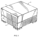
- Figure 1 illustrates a general purpose multi-disk drive enclosure.
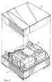
- Figure 2 illustrates the general positioning of the super-structure within the drive enclosure.
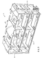
- Figure 3 illustrates the super-structure in perspective view.
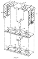
- Figure 4 illustrates the super-structure in exploded view.
- Figure 5 illustrates the bottom view of the super-structure showing a mounting bracket and illustrating a mounted disk drive.
- Figure 6 illustrates the drive belly plate
- Figure 7 illustrates a side member of the super-structure.
- Figure 8 illustrates a front view of the super-structure.
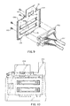
- Figure 9 illustrates an exploded view of the SCSI connectors and the SCSI attachment plate.
- Figure 10 illustrates a front view of the SCSI attachment holder with the SCSI attachment plate.
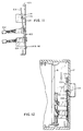
- Figure 11 illustrates a side view of the method of inserting the SCSI attachment plate into the attachment holder.
- Figure 12 illustrates a side view of the SCSI attachment plate and attachment holder as held in place by the top of the disk drive enclosure.
- a method and apparatus for mounting multiple disk drive units in a limited space enclosure are disclosed, which meet die International Electrotechnical Commission (“IEC”) 69 and 721 series of test standards, and which requires connections only on the side and bottom of the individual drive units.
- IEC International Electrotechnical Commission
- specific numbers, materials, and configurations are set forth in order to provide a thorough understanding of the present invention. However, it will be apparent to one skilled in the art that the present invention may be practiced without the specific details.
- the enclosure 10 is a parallelepiped box approximately 144 millimeters tall, by 244 millimeters wide, by 264 millimeters deep.
- the enclosure 10 has a top enclosure member 12 and a bottom enclosure member 14.
- Figure 2 shows the disk drive enclosure 10 with the top enclosure member 12 removed to expose the super-structure 16.
- Such multi-disk drive enclosures may be of any size, however the present invention is designed to minimize the footprint of the enclosure as well as the height of the box in order to make it stackable over previously released products, while using existing components in order to minimize cost.
- the footprint of a device is the area of desk or floor space occupied by the device.
- the super-structure 16 is shown in perspective view, and is comprised of a top member 18 , a bottom cross-member 22 , and an intermediate cross-member 26 which are essentially parallel to each other, and side members 20, 24 which are substantially perpendicular to top member 18, bottom cross-member 22 and intermediate cross-member 26.
- the super-structure 16 can accommodate four 3.5 inch form factor, full height disk drive units.
- An alternative configuration would include three cross-members (one 22 , and two 26s ), within the same size super-structure to accommodate six 3.5 inch forth factor, 1 inch high disk drive units.
- Figure 4 illustrates the super-structure 16 in exploded view in a preferred configuration, showing the mounting areas on the bottom cross-member 22 and the intermediate cross-member 26 .
- Each mounting area has a clip finger 54 and a left holding tab 50 and a right holding tab 52 for securely holding the drive belly plate 32 (see Figure 8 ) which is mounted on the bottom of a disk drive as illustrated below.
- the side members 20 and 24 are an integral part of the top member 18 , the side members being bent downward at a 90 degree angle to the top member.
- Figure 5 illustrates a bottom view of the super-structure 16 showing a disk drive 30 seated on one side of the bottom member 22 and an open slot on the other side of the bottom member 22 .
- the openings 58 , 60 and the clip finger 54 and a left holding tab 50 and a right holding tab 52 are illustrated. These holding tabs 50 , 52 and the holding finger 54 are used to hold down the disk drive 30 by engaging the clip plate 42 and the left holding area 38 and right holding area 40 on the drive belly plate 32 which is attached to the bottom of the disk drive 30 .
- the drive belly plate 32 is shown more clearly in Figure 6 , which illustrates the plate 32 connected to the bottom 34 of a disk drive 30 .
- the plate 32 is secured to the disk drive 30 by means of four hex screws 36 , two on either side.
- the drive belly plate 32 has a clip plate 42 area for engaging the clip finger ( 54 in Figure 5 ), a left holding area 38 and a right holding area 40 for engaging the holding tabs ( 50 , 52 in Figure 5 ) on the super-structure bottom or intermediate cross-members.
- the notch 44 on the drive belly plate 32 is used to correctly position the drive in the super-structure drive slot
- FIG. 7 the detail of a side member 24 of the super-structure is illustrated.
- a four drive configuration is illustrated with the side perspective showing two disk drives 30 , one mounted on the bottom cross-member (not shown) and one drive mounted on the intermediated crossmember (not shown).
- Each drive is attached to the side member 24 by means of two hex screws 70 .
- the bottom cross-member is attached to the side member 24 by means of the bottom connecting slots 80 .
- the intermediate cross-member is connected to the side member 24 by means of the middle connecting slots 72 .
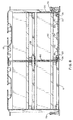
- FIG. 8 a front view of the super-structure 16 is shown illustrating the four drive configuration. Illustrated are the bottom cross-member 22 , the intermediate cross-member ber 26 and the top member 18 . Hold down connectors 78 are used to connect the super-structure 16 to the disk drive enclosure.
- the lower right disk drive 30 is shown connected to the bottom member 22 .
- a drive belly plate 32 is shown connected to the disk drive 30 by means of the belly plate connecting hex screws 36 , and with the left holding area 38 and a right holding area 40 on the belly plate 32 , engaging the holding tabs 52 and 50 .
- Figure 8 also illustrates the narrow clearance 90 between adjacent drives in this configuration. In the preferred embodiment this clearance is approximately two millimeters.
- the super-structure device is fabricated from zinc plated CRS material.
- Disk drives such as those used in this invention are normally electrically connected to other parts of a computer system by means of cables which terminate in Small Computer System Interface (SCSI) connectors.
- SCSI Small Computer System Interface
- Such connectors would normally be mounted on the inside rear of the disk drive enclosure by means of standard screws.
- an innovative SCSI connector clip mechanism which requires no direct screw connection to the disk drive enclosure also forms a part of this invention.
- FIG 9 illustrates the connection of the SCSI connectors 100 of the cables 102 from the disk drives 30 to a SCSI attachment plate 104 .
- the SCSI attachment plate 104 comprises a vertical member 106 having apertures 108 into which the SCSI connectors may be attached by hex screws 110 , the vertical member 106 having a clip finger 112 at the top, having holding tabs 114 and 116 at its foot, and seating restraint tabs 118 also on the top portion of the attachment plate.
- the SCSI connectors can be easily attached to this SCSI attachment plate either before the super-structure is attached inside the drive enclosure or afterward, since the attachment plate is not connected to anything at this point.
- Figure 10 illustrates the SCSI attachment plate 104 and its relationship to a SCSI attachment plate holder 120 .
- the SCSI attachment plate holder 120 is attached to the inside rear of the bottom enclosure member 14 as shown in Figure 12.
- Figure 11 provides a side view of the SCSI attachment plate 104 with cables 102 attached and illustrating the method of connecting the SCSI attachment plate 104 to the plate holder 120 .
- Holding tabs 114 & 116 are inserted into the aperture 122 for seating on the bottom lip 124 on the aperture 122 in the plate holder 120 .
- Clip finger 112 is connected to the top portion 126 of the plate holder 120 and seating restraint tabs 118 extend over the top portion 126 of plate holder 120 .
- a pair of locking tabs 130 connected to the inside rear of the top enclosure member 12, are used to provide abutting contact to the seating restraint tabs 118, to finnly lock the SCSI attachment plate 104 to the SCSI attachment plate holder 120 and thereby to the disk drive enclosure without the need for any screw attachment to the enclosure itself.
- SCSI connector mechanism has been described in connection with a two cable hook-up, it should be apparent to those skilled in the art that the SCSI connector mechanism architecture may be applied to other configurations of SCSI connectors and to other types of electrical connectors and that the disk drive mounting architecture described can be used in other environments and other configurations.
Landscapes
- Casings For Electric Apparatus (AREA)
- Automatic Disk Changers (AREA)
Claims (22)
- Un appareil en forme de boítier d'unités de disque caractérisé parune superstructure (16) comprenant:un organe transversal supérieur (18);un organe transversal inférieur (22), et un ou plusieurs organes transversaux intermédiaires (26), lesdits organes transversaux inférieur (22) et intermédiaires (26) étant sensiblement parallèles audit organe transversal supérieur (18) et lesdits organes transversaux inférieur (22) et intermédiaires (26) comportant des mécanismes connecteurs (50, 52, 54) pour venir en prise, de façon démontable, avec une unité (30) de disque; etdes organes latéraux (20, 24) connectés auxdits organes transversaux supérieur (28), inférieur (22) et intermédiaires (26) et lesdits organes latéraux (20, 24) étant sensiblement perpendiculaires auxdits organes transversaux supérieur (18), inférieur (22) et intermédiaires (26);ladite superstructure (16) étant située à l'intérieur de ladite enceinte (10) d'unités de disque dans laquelle au moins une unité (30) de disque peut être montée, ladite unité (30) de disque étant connectée à ladite superstructure (16) par des dispositifs connecteurs (70) sur l'un des côtés de ladite unité (30) de disque et par une plaque ventrale (32) d'unité connectée de façon démontable au bas de ladite unité (30) de disque,ladite plaque ventrale (32) d'unité venant en prise de façon démontable avec l'un desdits mécanismes connecteurs (50, 52, 54) de l'un desdits organes transversaux inférieur ou intermédiaires,lesdits dispositifs connecteurs (70) connectant de façon démontable l'unité (30) de disque à l'un desdits organes latéraux (20, 24) après insertion de ladite unité (30) de disque dans ladite superstructure (16), ladite plaque ventrale (32) d'unité étant en prise avec l'un desdits mécanismes connecteurs (50, 52, 54), de sorte que ladite unité (30) de disque est maintenue de façon sûre dans ladite enceinte en étant fixée par lesdits dispositifs connecteurs (70) sur l'un des côtés et par ladite plaque ventrale (32) d'unité sur le bas.
- L'appareil en forme de boítier d'unités de disque selon la revendication 1, dans lequel ladite superstructure (16) peut contenir jusqu'à quatre unités de disque.
- L'appareil en forme de boítier d'unités de disque selon la revendication 2, dans lequel lesdites quatre unités de disque sont des unités de disque à facteur de forme de 3,5 pouces de hauteur complète.
- L'appareil en forme de boítier d'unités de disque selon la revendication 1, dans lequel ladite superstructure (16) comprend deux organes transversaux intermédiaires (26) et peut contenir jusqu'à six unités de disque.
- L'appareil en forme de boítier d'unités de disque selon la revendication 4, dans lequel lesdites six unités de disque sont des unités de disque à facteur de forme de 3,5 pouces d'une hauteur d'un pouce, ou 25,4 mm.
- L'appareil en forme de boítier d'unités de disque selon la revendication 1, dans lequel ladite superstructure (16) est fabriquée en acier laminé à froid galvanisé.
- L'appareil en forme de boítier d'unités de disque selon la revendication 1, qui comprend en outre un assemblage de plaque d'attache de connecteurs électriques connecté audit boítier d'unités de disque sans utiliser aucune vis afin d'effectuer ladite connexion audit boítier d'unités de disque, et ladite unité (30) de disque étant attachée à des câbles (102) de raccordement, lesdits câbles (102) étant attachés à des connecteurs électriques (100) et lesdits connecteurs électriques (100) étant attachés audit assemblage de plaque d'attache de connecteurs électriques.
- L'appareil en forme de boítier d'unités de disque selon la revendication 7, dans lequel ledit assemblage de plaque d'attache de connecteurs électrique comprend:une plaque d'attache (104) de connecteurs électriques qui comprend un organe vertical (106) où sont ménagées des ouvertures (108) dans lesquelles lesdits connecteurs électriques (100) peuvent être attachés, ledit organe vertical (106) comportant aussi un doigt de pincement (112) et des pattes de guidage (118) d'appui sur un bord supérieur et comportant des pattes de maintien (114, 116) sur un bord inférieur.
- L'appareil en forme de boítier d'unités de disque selon la revendication 8, dans lequel ledit assemblage de plaque d'attache de connecteurs électriques comprend en outre un support (120) de plaque d'attache de connecteurs électriques qui est connecté à une section d'extrémité arrière dudit appareil en forme de boítier d'unités de disque, ledit support (120) de plaque d'attache de connecteurs électriques comportant une ouverture (122) dans laquelle lesdites pattes de maintien (114, 116) situées sur un bord inférieur dudit organe vertical (106) peuvent être insérées et s'appuyer sur un bord inférieur de ladite ouverture (122), et dans lequel ledit doigt de pincement (112) situé sur un bord supérieur dudit organe vertical (106) peut s'appuyer sur un bord supérieur dudit support (120) de plaque d'attache de connecteurs électriques.
- L'appareil en forme de boítier d'unités de disque selon la revendication 9, dans lequel un organe supérieur dudit boítier d'unités de disque contient -une paire de pattes de verrouillage (130) situées sur une face intérieure d'une partie arrière dudit organe supérieur dudit boítier d'unités de disque, lesdites pattes de verrouillage (130) réalisant un contact en butée avec lesdites pattes de guidage (118) d'appui situées sur un bord supérieur de ladite plaque d'attache de connecteurs électriques afin de verrouiller en place ladite plaque d'attache (104) de connecteurs électriques lorsque ledit organe supérieur dudit boítier d'unités de disque est fixé à un organe inférieur dudit boítier d'unités de disque qui contient ledit assemblage de plaque d'attache de connecteurs électriques.
- L'appareil en forme de boítier d'unités de disque selon la revendication 1, dans lequel lesdits mécanismes connecteurs desdits organes transversaux inférieur et intermédiaires comprennent des consoles de montage.
- Un procédé de montage d'une série d'unités de disque dans une enceinte (10) d'unités de disque d'informatique caractérisé par les étapes consistant à:agencer une superstructure (16) qui peut être située à l'intérieur de ladite enceinte (10), ladite superstructure (16) comprenant un organe transversal supérieur (18), un organe transversal inférieur (22), un ou plusieurs organes transversaux intermédiaires (26), lesdits organes transversaux supérieur (18), inférieur (22) et intermédiaires (26) étant sensiblement parallèles entre eux et étant connectés à des organes latéraux (20, 24) qui sont sensiblement perpendiculaires auxdits organes transversaux supérieur (18), inférieur (22) et intermédiaires (26); ladite superstructure (16) étant réalisée de façon à recevoir et supporter une série d'unités (30) de disque qui y sont montées, lesdits organes transversaux inférieur (22) et intermédiaires (26) comportant des consoles de montage (50, 52, 54) pour tenir lesdites unités (30) de disque;connecter une plaque ventrale (32) d'unité à une unité (30) de disque, ladite plaque ventrale (32) d'unité étant réalisée de manière à venir en prise de façon démontable avec l'une desdites consoles de montage (50, 52, 54);insérer ladite unité (30) de disque dans ladite superstructure (16), ladite plaque ventrale (32) d'unité venant en prise de façon démontable avec l'une desdites consoles de montage (50, 52, 54); etconnecter l'un des côtés de ladite unité (30) de disque à l'un desdits organes latéraux (20, 24),de sorte que ladite unité (30) de disque est maintenue de façon sûre dans ladite enceinte (10) en n'étant fixée que par une connexion audit organe latéral (20, 24) et par ladite plaque ventrale (32).
- Le procédé selon la revendication 12, dans lequel ladite enceinte (10) peut contenir jusqu'à quatre unités de disque.
- Le procédé selon la revendication 13, dans lequel lesdites quatre unités de disque sont des unités de disque à facteur de forme de 3,5 pouces de hauteur complète.
- Le procédé selon la revendication 12, dans lequel ladite superstructure (16) comprend deux organes transversaux intermédiaires (26) et peut contenir jusqu'à six unités de disque.
- Le procédé selon la revendication 13, dans lequel lesdites six unités de disque sont des unités de disque à facteur de forme de 3,5 pouces d'une hauteur de un pouce, ou 25,4 mm.
- Le procédé selon la revendication 12, dans lequel ladite superstructure (16) est en acier laminé à froid galvanisé.
- Le procédé selon la revendication 12, qui comprend en outre les étapes consistant àconnecter un assemblage de plaque d'attache de connecteurs électriques à ladite enceinte (10) d'unités de disque sans utiliser aucune vis afin d'effectuer ladite connexion à ladite enceinte (10) d'unités de disque, et lesdites unités (30) de disque étant attachées à des câbles (102) de raccordement, lesdits câbles (102) étant attachés à des connecteurs électriques (100) et lesdits connecteurs électriques (100) étant attachés audit assemblage de plaque d'attache de connecteurs électriques.
- Le procédé de montage d'une série d'unités de disque dans une enceinte d'unités de disque selon la revendication 18, dans lequel ledit assemblage de plaque d'attache de connecteurs électrique comprend:une plaque d'attache (104) de connecteurs électriques qui comprend un organe vertical (106) où sont ménagées des ouvertures (108) dans lesquelles lesdits connecteurs électriques (100) peuvent être attachés, ledit organe vertical (106) comportant aussi un doigt de pincement (112) et des pattes de guidage (118) d'appui sur un bord supérieur et comportant des pattes de maintien (114, 116) sur un bord inférieur.
- Le procédé de montage d'une série d'unités de disque dans une enceinte d'unités de disque selon la revendication 19, dans lequel ledit assemblage de plaque d'attache de connecteurs électriques comprend en outre un support (120) de plaque d'attache de connecteurs électriques et comprend en outre les étapes consistant à:connecter ledit support (120) de plaque d'attache de connecteurs électriques à une section d'extrémité arrière de ladite enceinte (10) d'unités de disque, ledit support (120) de plaque d'attache de connecteurs électriques comportant une ouverture (122);insérer dans ladite ouverture (122) dudit support (120) de plaque d'attache de connecteurs électriques lesdites pattes de maintien (114, 116) situées sur un bord inférieur dudit organe vertical de façon que lesdites pattes de maintien (114, 116) s'appuient sur un bord inférieur de ladite ouverture (122); etappuyer sur un bord supérieur dudit support (120) de plaque d'attache de connecteurs électriques ledit doigt de pincement (112) situé sur un bord supérieur dudit organe vertical (106).
- Le procédé de montage d'une série d'unités de disque dans une enceinte d'unités de disque selon la revendication 20, qui comprend les étapes additionnelles consistant àagencer une paire de pattes de verrouillage (130) situées sur une face intérieure d'une partie arrière de l'organe supérieur de ladite enceinte (10) d'unités de disque; etattacher sur un organe inférieur de ladite enceinte d'unités de disque ledit organe supérieur de ladite enceinte (10) d'unités de disque d'une manière telle que lesdites pattes de verrouillage (130) réalisent un contact en butée avec lesdites pattes de guidage (118) d'appui situées sur un bord supérieur de ladite plaque d'attache de connecteurs électriques afin de verrouiller en place ladite plaque d'attache (104) de connecteurs électriques.
- Un appareil en forme de boítier d'unités de disque selon la revendication 1, dans lequel ladite plaque ventrale (32) d'unité permet auxdites unités de disque d'être maintenues de façon amovible par rapport à une surface principale, et aucune contrainte n'est exercée, sur lesdites unités de disque, sur les côtés intérieurs adjacents desdites unités de disque.
Applications Claiming Priority (2)
| Application Number | Priority Date | Filing Date | Title |
|---|---|---|---|
| US08/084,826 US5503472A (en) | 1993-06-29 | 1993-06-29 | Method and apparatus for assembly of a multi-disk pack unit |
| US84826 | 1993-06-29 |
Publications (2)
| Publication Number | Publication Date |
|---|---|
| EP0632455A1 EP0632455A1 (fr) | 1995-01-04 |
| EP0632455B1 true EP0632455B1 (fr) | 1999-08-04 |
Family
ID=22187459
Family Applications (1)
| Application Number | Title | Priority Date | Filing Date |
|---|---|---|---|
| EP94302627A Expired - Lifetime EP0632455B1 (fr) | 1993-06-29 | 1994-04-13 | Une méthode et un appareil pour assembler plusieurs unités à disque |
Country Status (4)
| Country | Link |
|---|---|
| US (1) | US5503472A (fr) |
| EP (1) | EP0632455B1 (fr) |
| JP (1) | JP3708566B2 (fr) |
| DE (1) | DE69419845T2 (fr) |
Families Citing this family (24)
| Publication number | Priority date | Publication date | Assignee | Title |
|---|---|---|---|---|
| US5733024A (en) * | 1995-09-13 | 1998-03-31 | Silicon Valley Group, Inc. | Modular system |
| US5682291A (en) * | 1996-07-10 | 1997-10-28 | Dell U.S.A., L.P. | Carrier for a computer device |
| US5688030A (en) * | 1996-08-09 | 1997-11-18 | Dell Usa Lp | Electronic equipment enclosure with support members |
| US5680293A (en) * | 1996-09-13 | 1997-10-21 | Dell U.S.A., L.P. | Screwless hard drive mounting in a computer system with a chassis via a first bracket rigidly mounted to the chassis and a second bracket movably mounted to the chassis |
| US5858509A (en) * | 1996-11-15 | 1999-01-12 | Digital Equipment Corporation | Attenuating vibrations in a mounting shelf for multiple disk drives |
| US5926366A (en) * | 1996-11-15 | 1999-07-20 | Digital Equipment Corporation | Tab and slot disk drive vibration reduction structure |
| TW364610U (en) * | 1998-01-15 | 1999-07-11 | Hon Hai Prec Ind Co Ltd | Seperatable fastening equipment for computer modules |
| US6064568A (en) * | 1998-01-27 | 2000-05-16 | Dell Usa, L.P. | Computer system with peripheral device carrier |
| US6272010B1 (en) | 1998-01-27 | 2001-08-07 | Dell Usa, L.P. | Peripheral device mounting apparatus |
| US6160703A (en) * | 1998-06-23 | 2000-12-12 | Hewlett-Packard Company | Shock mounting system for data storage modules |
| US5934775A (en) * | 1998-08-26 | 1999-08-10 | Ho; Hsin Chien | Quick release terminal holder mounting arrangement for a computer |
| US6154361A (en) * | 1998-10-02 | 2000-11-28 | International Business Machines Corporation | Disk-drive chassis for reducing transmission of vibrations between disk-drive units of a disk-drive array |
| TW412137U (en) * | 1999-04-16 | 2000-11-11 | Hon Hai Prec Ind Co Ltd | Fastening apparatus for data access medium |
| US6525930B1 (en) * | 1999-10-08 | 2003-02-25 | Sun Microsystems, Inc. | Mounting media drives in a computer system on a carriage |
| US7240976B2 (en) * | 2001-04-23 | 2007-07-10 | Tektronix, Inc. | Modular rack-mounting system |
| TWM244638U (en) * | 2002-12-27 | 2004-09-21 | Coretronic Corp | Fixing structure |
| US6853548B2 (en) * | 2003-01-02 | 2005-02-08 | Quantum Corporation | 1U rack mount equipment enclosure with increased structural support |
| USD520994S1 (en) * | 2003-09-05 | 2006-05-16 | Maxtor Corporation | External backup storage |
| USD521510S1 (en) * | 2005-07-12 | 2006-05-23 | D-Link Corporation | Network device |
| TWM292143U (en) * | 2005-12-29 | 2006-06-11 | Inventec Corp | Fastened mechanism of a retractable device |
| TW201228540A (en) * | 2010-12-30 | 2012-07-01 | Hon Hai Prec Ind Co Ltd | Electronic device enclosure |
| CN102548272A (zh) * | 2010-12-31 | 2012-07-04 | 鸿富锦精密工业(深圳)有限公司 | 电子装置壳体 |
| US10314191B2 (en) * | 2015-08-04 | 2019-06-04 | Mitsubishi Electric Corporation | Assembly alignment assistance structure for member, and casing of electronic device |
| JP7362327B2 (ja) | 2019-07-18 | 2023-10-17 | 東京エレクトロン株式会社 | ターゲット構造体及び成膜装置 |
Family Cites Families (7)
| Publication number | Priority date | Publication date | Assignee | Title |
|---|---|---|---|---|
| JPS5855576Y2 (ja) * | 1980-05-07 | 1983-12-20 | クラリオン株式会社 | コネクタ−固定装置 |
| US4717982A (en) * | 1984-08-31 | 1988-01-05 | Xebec | Electrical connector retaining assembly for facilitating removable mounting of a rigid disk drive |
| FR2652940B1 (fr) * | 1989-10-05 | 1994-03-11 | Bull Sa | Dispositif de fixation de peripheriques d'ordinateur. |
| US5047898A (en) * | 1989-11-13 | 1991-09-10 | International Business Machines Corporation | Deflectable contact for providing positive surface contact for shielding electromagnetic interference |
| DE4131661C1 (fr) * | 1991-09-23 | 1993-04-01 | Siemens Nixdorf Informationssysteme Ag, 4790 Paderborn, De | |
| US5277615A (en) * | 1992-09-24 | 1994-01-11 | Compaq Computer Corporation | Apparatus for removably supporting a plurality of hot plug-connected hard disk drives |
| US5306079A (en) * | 1992-10-08 | 1994-04-26 | Enlight Corporation | Multi-purpose frame for a computer |
-
1993
- 1993-06-29 US US08/084,826 patent/US5503472A/en not_active Expired - Lifetime
-
1994
- 1994-04-13 DE DE69419845T patent/DE69419845T2/de not_active Expired - Fee Related
- 1994-04-13 EP EP94302627A patent/EP0632455B1/fr not_active Expired - Lifetime
- 1994-05-17 JP JP12589394A patent/JP3708566B2/ja not_active Expired - Fee Related
Also Published As
| Publication number | Publication date |
|---|---|
| JP3708566B2 (ja) | 2005-10-19 |
| US5503472A (en) | 1996-04-02 |
| JPH0721760A (ja) | 1995-01-24 |
| DE69419845T2 (de) | 2000-02-24 |
| DE69419845D1 (de) | 1999-09-09 |
| EP0632455A1 (fr) | 1995-01-04 |
Similar Documents
| Publication | Publication Date | Title |
|---|---|---|
| EP0632455B1 (fr) | Une méthode et un appareil pour assembler plusieurs unités à disque | |
| US5291368A (en) | Printed circuit board frame module assembly | |
| US5682291A (en) | Carrier for a computer device | |
| US5339221A (en) | Printed circuit board mounting cage | |
| US5031075A (en) | Double-sided logic cage | |
| US5808871A (en) | Modular computer tower assembly | |
| US5689406A (en) | Expandable data processing chassis and method of assembly thereof | |
| US6404624B1 (en) | Structure for mounting electronic devices to a computer main body | |
| US6018456A (en) | Enclosure for removable computer peripheral equipment | |
| US6661667B2 (en) | Sub rack based vertical housing for computer systems | |
| JPH0779199B2 (ja) | 電子モジュール相互接続システム | |
| US4699270A (en) | Modular packaging system | |
| US6238026B1 (en) | System for mounting components in a computer chassis | |
| US6404641B1 (en) | Tool-less quick release latching mechanism for use with a carrier and a compartment of an enclosure | |
| EP0438012A2 (fr) | Dispositif pour fond de panier double face | |
| JPH029200A (ja) | パッケージ構造 | |
| US20030206398A1 (en) | Method and apparatus for mounting a backplane in a chassis | |
| WO2010101911A1 (fr) | Module pouvant être monté à l'envers à double crochet et panneau doté d'une ouverture permettant le montage de multiples modules | |
| US6522551B2 (en) | Method and apparatus for mounting electronic components within a rack system | |
| US4984133A (en) | Unitized central electronics complex construction | |
| US5224020A (en) | Electronic apparatus having modular front and back functional units and electrical distribution unit including a fan therebetween | |
| US6954353B2 (en) | Modular logic board chassis for a desktop computer | |
| US20030161116A1 (en) | Adjustable sled module for mass storage devices | |
| US5496181A (en) | Serviceable data terminal structure | |
| US6046913A (en) | Panel mounted power module with adaptor mounting bracket |
Legal Events
| Date | Code | Title | Description |
|---|---|---|---|
| PUAI | Public reference made under article 153(3) epc to a published international application that has entered the european phase |
Free format text: ORIGINAL CODE: 0009012 |
|
| AK | Designated contracting states |
Kind code of ref document: A1 Designated state(s): DE FR GB IT NL |
|
| 17P | Request for examination filed |
Effective date: 19950501 |
|
| 17Q | First examination report despatched |
Effective date: 19971031 |
|
| GRAG | Despatch of communication of intention to grant |
Free format text: ORIGINAL CODE: EPIDOS AGRA |
|
| GRAG | Despatch of communication of intention to grant |
Free format text: ORIGINAL CODE: EPIDOS AGRA |
|
| GRAH | Despatch of communication of intention to grant a patent |
Free format text: ORIGINAL CODE: EPIDOS IGRA |
|
| GRAG | Despatch of communication of intention to grant |
Free format text: ORIGINAL CODE: EPIDOS AGRA |
|
| GRAH | Despatch of communication of intention to grant a patent |
Free format text: ORIGINAL CODE: EPIDOS IGRA |
|
| GRAH | Despatch of communication of intention to grant a patent |
Free format text: ORIGINAL CODE: EPIDOS IGRA |
|
| GRAA | (expected) grant |
Free format text: ORIGINAL CODE: 0009210 |
|
| AK | Designated contracting states |
Kind code of ref document: B1 Designated state(s): DE FR GB IT NL |
|
| PG25 | Lapsed in a contracting state [announced via postgrant information from national office to epo] |
Ref country code: IT Free format text: LAPSE BECAUSE OF FAILURE TO SUBMIT A TRANSLATION OF THE DESCRIPTION OR TO PAY THE FEE WITHIN THE PRE;WARNING: LAPSES OF ITALIAN PATENTS WITH EFFECTIVE DATE BEFORE 2007 MAY HAVE OCCURRED AT ANY TIME BEFORE 2007. THE CORRECT EFFECTIVE DATE MAY BE DIFFERENT FROM THE ONE RECORDED.SCRIBED TIME-LIMIT Effective date: 19990804 |
|
| REF | Corresponds to: |
Ref document number: 69419845 Country of ref document: DE Date of ref document: 19990909 |
|
| ET | Fr: translation filed | ||
| PLBE | No opposition filed within time limit |
Free format text: ORIGINAL CODE: 0009261 |
|
| STAA | Information on the status of an ep patent application or granted ep patent |
Free format text: STATUS: NO OPPOSITION FILED WITHIN TIME LIMIT |
|
| 26N | No opposition filed | ||
| REG | Reference to a national code |
Ref country code: GB Ref legal event code: IF02 |
|
| PGFP | Annual fee paid to national office [announced via postgrant information from national office to epo] |
Ref country code: NL Payment date: 20030429 Year of fee payment: 10 |
|
| PGFP | Annual fee paid to national office [announced via postgrant information from national office to epo] |
Ref country code: GB Payment date: 20040407 Year of fee payment: 11 |
|
| PGFP | Annual fee paid to national office [announced via postgrant information from national office to epo] |
Ref country code: FR Payment date: 20040408 Year of fee payment: 11 |
|
| PGFP | Annual fee paid to national office [announced via postgrant information from national office to epo] |
Ref country code: DE Payment date: 20040422 Year of fee payment: 11 |
|
| PG25 | Lapsed in a contracting state [announced via postgrant information from national office to epo] |
Ref country code: NL Free format text: LAPSE BECAUSE OF NON-PAYMENT OF DUE FEES Effective date: 20041101 |
|
| NLV4 | Nl: lapsed or anulled due to non-payment of the annual fee |
Effective date: 20041101 |
|
| PG25 | Lapsed in a contracting state [announced via postgrant information from national office to epo] |
Ref country code: GB Free format text: LAPSE BECAUSE OF NON-PAYMENT OF DUE FEES Effective date: 20050413 |
|
| PG25 | Lapsed in a contracting state [announced via postgrant information from national office to epo] |
Ref country code: DE Free format text: LAPSE BECAUSE OF NON-PAYMENT OF DUE FEES Effective date: 20051101 |
|
| GBPC | Gb: european patent ceased through non-payment of renewal fee |
Effective date: 20050413 |
|
| PG25 | Lapsed in a contracting state [announced via postgrant information from national office to epo] |
Ref country code: FR Free format text: LAPSE BECAUSE OF NON-PAYMENT OF DUE FEES Effective date: 20051230 |
|
| REG | Reference to a national code |
Ref country code: FR Ref legal event code: ST Effective date: 20051230 |