EP0632475A1 - Structure de support de manipulateur pour interrupteur multidirectionnel - Google Patents
Structure de support de manipulateur pour interrupteur multidirectionnel Download PDFInfo
- Publication number
- EP0632475A1 EP0632475A1 EP94110020A EP94110020A EP0632475A1 EP 0632475 A1 EP0632475 A1 EP 0632475A1 EP 94110020 A EP94110020 A EP 94110020A EP 94110020 A EP94110020 A EP 94110020A EP 0632475 A1 EP0632475 A1 EP 0632475A1
- Authority
- EP
- European Patent Office
- Prior art keywords
- joy stick
- switch
- contact
- switch portions
- portions
- Prior art date
- Legal status (The legal status is an assumption and is not a legal conclusion. Google has not performed a legal analysis and makes no representation as to the accuracy of the status listed.)
- Granted
Links
- 230000007935 neutral effect Effects 0.000 claims abstract description 23
- 230000002093 peripheral effect Effects 0.000 claims abstract description 16
- 239000000428 dust Substances 0.000 description 3
- 238000005299 abrasion Methods 0.000 description 1
- 230000006866 deterioration Effects 0.000 description 1
- 239000000463 material Substances 0.000 description 1
- 230000004048 modification Effects 0.000 description 1
- 238000012986 modification Methods 0.000 description 1
- 239000000843 powder Substances 0.000 description 1
- 229920003002 synthetic resin Polymers 0.000 description 1
- 239000000057 synthetic resin Substances 0.000 description 1
Images


Classifications
-
- G—PHYSICS
- G05—CONTROLLING; REGULATING
- G05G—CONTROL DEVICES OR SYSTEMS INSOFAR AS CHARACTERISED BY MECHANICAL FEATURES ONLY
- G05G9/00—Manually-actuated control mechanisms provided with one single controlling member co-operating with two or more controlled members, e.g. selectively, simultaneously
- G05G9/02—Manually-actuated control mechanisms provided with one single controlling member co-operating with two or more controlled members, e.g. selectively, simultaneously the controlling member being movable in different independent ways, movement in each individual way actuating one controlled member only
- G05G9/04—Manually-actuated control mechanisms provided with one single controlling member co-operating with two or more controlled members, e.g. selectively, simultaneously the controlling member being movable in different independent ways, movement in each individual way actuating one controlled member only in which movement in two or more ways can occur simultaneously
- G05G9/047—Manually-actuated control mechanisms provided with one single controlling member co-operating with two or more controlled members, e.g. selectively, simultaneously the controlling member being movable in different independent ways, movement in each individual way actuating one controlled member only in which movement in two or more ways can occur simultaneously the controlling member being movable by hand about orthogonal axes, e.g. joysticks
- G05G9/04785—Manually-actuated control mechanisms provided with one single controlling member co-operating with two or more controlled members, e.g. selectively, simultaneously the controlling member being movable in different independent ways, movement in each individual way actuating one controlled member only in which movement in two or more ways can occur simultaneously the controlling member being movable by hand about orthogonal axes, e.g. joysticks the controlling member being the operating part of a switch arrangement
-
- H—ELECTRICITY
- H01—ELECTRIC ELEMENTS
- H01H—ELECTRIC SWITCHES; RELAYS; SELECTORS; EMERGENCY PROTECTIVE DEVICES
- H01H25/00—Switches with compound movement of handle or other operating part
- H01H25/04—Operating part movable angularly in more than one plane, e.g. joystick
- H01H25/041—Operating part movable angularly in more than one plane, e.g. joystick having a generally flat operating member depressible at different locations to operate different controls
- H01H2025/046—Operating part movable angularly in more than one plane, e.g. joystick having a generally flat operating member depressible at different locations to operate different controls having a spherical bearing between operating member and housing or bezel
-
- Y—GENERAL TAGGING OF NEW TECHNOLOGICAL DEVELOPMENTS; GENERAL TAGGING OF CROSS-SECTIONAL TECHNOLOGIES SPANNING OVER SEVERAL SECTIONS OF THE IPC; TECHNICAL SUBJECTS COVERED BY FORMER USPC CROSS-REFERENCE ART COLLECTIONS [XRACs] AND DIGESTS
- Y10—TECHNICAL SUBJECTS COVERED BY FORMER USPC
- Y10T—TECHNICAL SUBJECTS COVERED BY FORMER US CLASSIFICATION
- Y10T74/00—Machine element or mechanism
- Y10T74/20—Control lever and linkage systems
- Y10T74/20012—Multiple controlled elements
- Y10T74/20201—Control moves in two planes
Definitions
- the present invention relates to a joy stick support structure for a multi-directional switch for selectively controlling a plurality of switch portions.
- the prior art multi-directional switch includes four switch portions formed on a printed wiring board or the like, a joy stick supported pivotally about a pivot fulcrum located centrally of the four switch portions, and a spring element such as a coil spring and a plate spring for returning the joy stick to its neutral position.
- An operating portion of the joy stick which projects from a through hole of a panel is inclined against the elastic force of the spring element, to incline the joy stick.
- One of the switch portions is selectively turned into the on position by the joy stick, depending on the direction of the inclination. When the operating force exerted upon the joy stick is released, the elastic force accumulated in the spring element forces the joy stick to return to the neutral position, and the one switch portion is returned to the off position by the restoring force thereof.
- the above-mentioned prior art multi-directional switch structure is of the type wherein the joy stick is returned to the neutral position by the spring element such as a coil spring and a plate spring.
- the spring element such as a coil spring and a plate spring.
- an additional spring element such as a coil spring and a plate spring is required to return the joy stick to the neutral position, which results in an increased number of parts and the increased total size of the structure.
- the present invention is intended for a joy stick support structure for a multi-directional switch, the multi-directional switch including a plurality of switch portions released and restored by an elastic restoring force, a joy stick having an operating portion and supported returnably to a neutral position, the joy stick being inclined by the operating portion to selectively operate the plurality of switch portions, and a cover panel for covering the switch portions and having a through hole through which the operating portion projects.
- the joy stick comprises a support portion supported pivotally about one end thereof adjacent the switch portions of the multi-directional switch, a slidable contact spherical portion bulging from the other end of the support portion and having a spherical surface slidably abutting throughout the entire circumference thereof against an inner peripheral surface of the through hole when pivoted, the operating portion projecting from the spherical surface.
- An outer periphery of the slidable contact spherical portion adjacent the support portion is supported in at least three circumferentially spaced positions so that the joy stick is returned to the neutral position by the elastic restoring force of the switch portions.
- the joy stick when the operating portion of the joy stick projecting through the through hole of the cover panel is pressed in a predetermined direction, the joy stick is inclined about one end of the support portion. The inclination of the joy stick permits the slidable contact spherical portion to selectively switch on a desired switch portion.
- the through hole of the cover panel is constantly covered with the spherical surface of the slidable contact spherical portion slidably abutting thereagainst during the inclination of the joy stick, requiring no parts for concealing the interior of the switch and effectively preventing dust from entering the interior of the switch.
- the cover panel comprises at least three point contact support projections formed in circumferentially spaced relation on an inner peripheral surface of the through hole.
- the joy stick comprises a support portion supported pivotally about one end thereof adjacent the switch portions of the multi-directional switch, a slidable contact spherical portion bulging from the other end of the support portion and having a spherical surface in point contact with the point contact support projections, the spherical surface being slidable in point contact with the point contact support projections when pivoted, the operating portion projecting from the spherical surface.
- An outer periphery of the slidable contact spherical portion adjacent the support portion is supported in at least three circumferentially spaced positions so that the joy stick is returned to the neutral position by the elastic restoring force of the switch portions.
- the slidable contact spherical portion of the joy stick slides in point contact with the point contact support projections formed on the inner peripheral surface of the through hole of the cover panel during the inclination of the joy stick.
- the frictional resistance is very small at the contact between the joy stick and the cover panel, and the joy stick is smoothly inclined, thereby providing a good operating feeling.
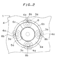
- a multi-directional switch 1 comprises a printed wiring board 2 having a suitably formed wiring pattern, a rubber contact switch sheet 3 made of a rubber material or the like and including elastically deformable contact switch portions 3a, a guide plate 4, a cover panel 5, and a joy stick 6.
- the elements 4, 5 and 6 are made of a synthetic resin or the like.
- the rubber contract switch sheet 3 includes the four bulging contact switch portions 3a constantly spaced in a circumferential direction of a circle having a desired diameter. As shown in Fig. 1, the rubber contact switch sheet 3 is superposed upon the printed wiring board 2 so that the contact switch portions 3a project upwardly.
- Contacts 2a of the printed wiring board 2 and contacts 3b of the contact switch portions 3a are opposed to each other in vertically suitably spaced relation.
- the respective contacts 2a and 3b form a plurality of freely connectable/disconnectable switch portions.
- the guide plate 4 is superposed upon the rubber contact switch sheet 3, as shown in Fig. 1.
- Vertical circular recesses 4a are formed in a lower surface of the guide plate 4 in corresponding relation to the contact switch portions 3a to house the contact switches 3a, respectively.
- the guide plate 4 further includes vertical guide holes 4b formed therethrough at the center of the bottom of the respective circular recesses 4a.
- Cooperating rods 8 each includes a disc portion 8a vertically slidably guided along the inner peripheral surface of the corresponding circular recess 4a, and a guide rod 8b vertically slidably guided along the inner peripheral surface of the corresponding guide hole 4b.
- the disc portions 8a are disposed on the upper surface of the contact switch portions 3a, and the guide rods 8b project upwardly from the guide holes 4b, respectively.
- Each of the guide rods 8b of the cooperating rods 8 has a hemispherical top end.
- the guide plate 4 further includes a fulcrum recess 4c in the upper surface thereof at the center of the circular recesses 4a.
- the joy stick 6 includes a support portion 6a, a slidable contact spherical portion 6b, and an operating portion 6c, which are disposed coaxially in this order, as shown in Fig. 1.
- the bottom end of the support portion 6a is received in the fulcrum recess 4c of the guide plate 4 serving as a body, and the joy stick 6 is supported pivotally about the received bottom end of the support portion 6a.
- the slidable contact spherical portion 6b bulges from the top end of the support portion 6a.
- the lower end surface of the slidable contact spherical portion 6b includes a flat surface 6d perpendicular to the axis of the support portion 6a and is of circular configuration about the axis of the support portion 6a.
- the upper surface of the slidable contact spherical portion 6b includes a spherical surface 6e centered on the pivot center at the bottom end of the support portion 6a.
- the slidable contact spherical portion 6b is of a so-called hemispherical configuration.
- the outer periphery of the flat surface 6d is urged upwardly and supported at circumferentially equally spaced positions by the elastic restoring force of the contact switch portions 3a from the top ends of the guide rods 8 of the cooperating rods 8.
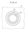
- the spherical surface 6e slidably abuts throughout the entire circumference thereof against a circumferentially continuous, circular ledge 5b formed on the inner peripheral surface of a circular through hole 5a of the cover panel 5, as shown in Figs. 3 and 4.
- the operating portion 6c at the center of the spherical surface 6e projects upwardly through the through hole 5a of the cover panel 5 for covering the guide plate 4, the cooperating rods 8, and the joy stick 6.
- the joy stick 6 is adapted such that the outer periphery of the flat surface 6d is urged upwardly at the circumferentially equally spaced positions by the elastic restoring force of the contact switch portions 3a through the cooperating rods 8, and the spherical surface 6e of the joy stick 6 abuts against the ledge 5b of the cover panel 5 by the urging force, thereby effectively preventing the joy stick 6 from being unsteady.
- the joy stick 6 when the operating portion 6c of the joy stick 6 is pushed leftwardly, the joy stick 6 is inclined about the bottom end of the support portion 6a serving as the fulcrum.
- the support recess 4c receives and supports the bottom end of the support portion 6a of the joy stick 6.
- the structure of the first preferred embodiment is of the type wherein the joy stick 6 is inclined under the urging force of at least one of the contact switch portions 3a.
- the spherical surface 6e of the slidable contact spherical portion 6b constantly slides along the ledge 5b of the cover panel 5. This provides a stable operating feeling without a securely determined fulcrum.
- the inclination of the joy stick 6 causes the outer periphery of the flat surface 6d of the slidable contact spherical portion 6b to press one of the cooperating rods 8 downwardly under guidance of the corresponding guide hole 4b. Then the corresponding contact switch portion 3a is pressed downwardly against the elastic force thereof by the corresponding disc portion 8a of the operating rod 8, and the corresponding contacts 2a and 3b come in contact with each other into the on position.
- the structure of the first preferred embodiment is of the type wherein the joy stick 6 is returned to the neutral position by the elastic restoring force of the respective contact switch portions 3a, there is no need to provide an additional member for returning the joy stick 6 to the neutral position such as the prior art coil spring or plate spring. Further, it is unnecessary to securely determine the fulcrum of the joy stick 6, which provides for reduction in the number of parts and, accordingly, facilitates the structure. This permits cost reduction, space reduction, and improvement in productivity.
- the spherical surface 6e of the slidable contact spherical portion 6b of the joy stick 6 constantly covers the through hole 5a of the cover panel 5 in a closing manner during the inclination of the joy stick 6. This structure requires no parts for concealing the interior of the multi-directional switch 1 and effectively prevents dust from entering the interior of the multi-directional switch 1.
- the structure includes the four switch portions in the first preferred embodiment, three or five switch portions may be provided, and the number of switch portions is not limited to that of the first preferred embodiment.
- the structure of the switch portions is not limited to that of the first preferred embodiment, and various types of switch portions are applicable which are automatically restored by the elastic restoring force.
- the single switch portion is operated by the inclination of the joy stick 6 in the first preferred embodiment, a plurality of switch portions may be simultaneously operated.
- a second preferred embodiment will be discussed hereinafter according to the present invention.
- Like reference numerals and characters are used to designate parts identical with those of the first preferred embodiment, and the description thereof will be omitted herein.
- the joy stick 6 is adapted such that the outer periphery of the flat surface 6d is supported and urged upwardly at circumferentially equally spaced positions by the elastic restoring force of the contact switch portions 3a from the top ends of the guide rods 8b of the cooperating rods 8.
- the spherical surface 6e is in point contact with and relatively slidably supported by four point contact support projections 5c formed in circumferentially equally spaced relation on the inner peripheral surface of the circular through hole 5a of the cover panel 5.
- the joy stick 6 is adapted such that the outer periphery of the flat surface 6d is urged upwardly at the circumferentially equally spaced positions by the elastic restoring force of the contact switch portions 3a through the respective cooperating rods 8, and the spherical surface 6e of the joy stick 6 abuts against the respective point contact support projections 5c by the urging force, thereby effectively preventing the joy stick 6 from being unsteady.
- the joy stick 6 when the operating portion 6c of the joy stick 6 is pushed leftwardly, the joy stick 6 is inclined about the bottom end of the support portion 6a serving as the fulcrum.
- the fulcrum recess 4c receives and supports the bottom end of the support portion 6a of the joy stick 6.
- the structure of the second preferred embodiment is of the type wherein the joy stick 6 is inclined under the urging force of at least one of the contact switch portions 3a.
- the spherical surface 6e of the slidable contact spherical portion 6b constantly slides in point contact with the respective point contact support projections 5c of the cover panel 5. This provides a stable operating feeling without the securely determined fulcrum.
- the inclination of the joy stick 6 causes the outer periphery of the flat surface 6d of the slidable contact spherical portion 6b to press one of the cooperating rod 8 downwardly under guidance of the corresponding guide hole 4b. Then the corresponding contact switch portion 3a is forced downwardly against the elastic force thereof by the corresponding disc portion 8a of the cooperating rod 8, and the corresponding contacts 2a and 3b come in contact with each other into the on position.
- the structure of the second preferred embodiment is of the type wherein the joy stick 6 is returned to the neutral position by the elastic restoring force of the respective contact switch portions 3a, there is no need to provide an additional member for returning the joy stick 6 to the neutral position such as the prior art coil spring or plate spring. Furthermore, it is unnecessary to securely determine the fulcrum of the joy stick 6, which provides for reduction in the number of parts and, accordingly, facilitate the structure. This permits cost reduction, space reduction, and improvement in productivity.
- the second preferred embodiment is less influenced by dust or powders made due to abrasion but provides a constantly stable, good operating feeling.
- the structure includes the four switch portions in the second preferred embodiment, three or five switch portions may be provided, and the number of switch portions is not limited to that of the second preferred embodiment.
- the structure includes the four point contact support projections 5c in the second preferred embodiment, three or five point contact support projections may be provided, and the number of point contact support projections is not limited to that of the second preferred embodiment.
- the structure of the switch portions is not limited to that of the second preferred embodiment, and various types of switch portions are applicable which are automatically restored by the elastic restoring force.
- the single switch portion is operated by the inclination of the joy stick 6 in the second preferred embodiment, a plurality of switch portions may be simultaneously operated.
Landscapes
- Physics & Mathematics (AREA)
- General Physics & Mathematics (AREA)
- Engineering & Computer Science (AREA)
- Automation & Control Theory (AREA)
- Switches With Compound Operations (AREA)
Applications Claiming Priority (4)
| Application Number | Priority Date | Filing Date | Title |
|---|---|---|---|
| JP5190790A JP3052679B2 (ja) | 1993-07-01 | 1993-07-01 | 多方向スイッチにおけるジョイスティック支持構造 |
| JP190790/93 | 1993-07-01 | ||
| JP1993054760U JP2578310Y2 (ja) | 1993-09-13 | 1993-09-13 | 多方向スイッチにおけるジョイスティック支持構造 |
| JP54760/93U | 1993-09-13 |
Publications (2)
| Publication Number | Publication Date |
|---|---|
| EP0632475A1 true EP0632475A1 (fr) | 1995-01-04 |
| EP0632475B1 EP0632475B1 (fr) | 1997-09-03 |
Family
ID=26395576
Family Applications (1)
| Application Number | Title | Priority Date | Filing Date |
|---|---|---|---|
| EP94110020A Expired - Lifetime EP0632475B1 (fr) | 1993-07-01 | 1994-06-28 | Structure de support de manipulateur pour interrupteur multidirectionnel |
Country Status (3)
| Country | Link |
|---|---|
| US (1) | US5468924A (fr) |
| EP (1) | EP0632475B1 (fr) |
| DE (1) | DE69405316T2 (fr) |
Cited By (6)
| Publication number | Priority date | Publication date | Assignee | Title |
|---|---|---|---|---|
| US6377239B1 (en) | 1998-05-26 | 2002-04-23 | Alps Electric Co., Ltd. | Multidirectional input device |
| DE10151603C1 (de) * | 2001-10-18 | 2003-03-20 | Kostal Leopold Gmbh & Co Kg | Mehrwege-Schalteranordnung, sowie Schalterbaustein |
| EP0903659A3 (fr) * | 1997-09-22 | 2003-10-29 | Sony Computer Entertainment Inc. | Dispositif de commande pour une console de jeux |
| DE102007013678A1 (de) * | 2007-03-22 | 2008-09-25 | Preh Gmbh | Bedienelement für ein Kraftfahrzeug |
| EP3740292A2 (fr) * | 2018-04-02 | 2020-11-25 | Google LLC | Dispositif d'entrée pour système électronique |
| US12280314B2 (en) | 2018-04-02 | 2025-04-22 | Google Llc | Methods, devices, and systems for interactive cloud gaming |
Families Citing this family (26)
| Publication number | Priority date | Publication date | Assignee | Title |
|---|---|---|---|---|
| US5691517A (en) * | 1993-11-19 | 1997-11-25 | Sumitomo Wiring Systems, Ltd. | Multidirectional lever switch device |
| JP3315245B2 (ja) * | 1994-05-12 | 2002-08-19 | アルプス電気株式会社 | 多方向入力スイッチ |
| US5576704A (en) * | 1994-12-01 | 1996-11-19 | Caterpillar Inc. | Capacitive joystick apparatus |
| US5744765A (en) * | 1995-06-19 | 1998-04-28 | Sumitomo Wiring Systems, Ltd. | Lever switch with support walls for supporting movable contact points and method of detecting an operating direction of a lever switch |
| US5619195A (en) * | 1995-12-29 | 1997-04-08 | Charles D. Hayes | Multi-axial position sensing apparatus |
| WO1997033431A1 (fr) * | 1996-03-05 | 1997-09-12 | Citizen Watch Co., Ltd. | Affichage a cristaux liquides |
| US5823057A (en) * | 1996-08-16 | 1998-10-20 | Hsien; Ming-Kun | Joy stick structure |
| JP3638071B2 (ja) * | 1997-01-31 | 2005-04-13 | 矢崎総業株式会社 | システムスイッチ |
| TW445426B (en) * | 1997-05-10 | 2001-07-11 | Acer Peripherals Inc | Capacitance sensing type pointing device |
| FR2765359B1 (fr) * | 1997-06-30 | 1999-09-10 | Mannesmann Rexroth Sa | Dispositif de telecommande a actionnement manuel, notamment manipulateur hydraulique |
| JP3911800B2 (ja) * | 1997-11-10 | 2007-05-09 | 松下電器産業株式会社 | 多方向操作スイッチ |
| DE19756052C2 (de) * | 1997-12-17 | 2002-06-27 | Trw Automotive Electron & Comp | Mehrfunktionsschalter |
| JP4018813B2 (ja) * | 1998-07-03 | 2007-12-05 | 富士通株式会社 | 携帯電話機 |
| JP3968944B2 (ja) * | 2000-03-15 | 2007-08-29 | 松下電器産業株式会社 | 車載用多方向操作スイッチ及びこれを用いた操作ユニット |
| JP2001331272A (ja) * | 2000-05-24 | 2001-11-30 | Alps Electric Co Ltd | 文字入力装置 |
| WO2002001589A1 (fr) * | 2000-06-29 | 2002-01-03 | Sk Developments Limited | Dispositif d'entree d'utilisateur pour un appareil de simulation de jeu |
| JP2002260493A (ja) * | 2001-03-06 | 2002-09-13 | Alps Electric Co Ltd | 4方向スイッチ装置 |
| US7280098B2 (en) * | 2003-05-08 | 2007-10-09 | Komelson Brent A | Joystick housing and mounting bracket |
| JP2005122686A (ja) * | 2003-09-22 | 2005-05-12 | Ntt Docomo Inc | 入力キー及び入力装置 |
| EP1524680B1 (fr) * | 2003-10-14 | 2007-12-19 | Alps Electric Co., Ltd. | Manipulateur à actionnement multimode |
| JP2005242983A (ja) * | 2004-01-30 | 2005-09-08 | Ntt Docomo Inc | 入力キー及び入力装置 |
| JP4317741B2 (ja) * | 2003-12-24 | 2009-08-19 | アルプス電気株式会社 | 4方向スイッチ装置 |
| US7507923B2 (en) * | 2005-12-05 | 2009-03-24 | Omron Dualtec Automotive Electronics Inc. | Electrical switch |
| JP5498362B2 (ja) * | 2010-11-24 | 2014-05-21 | 株式会社東海理化電機製作所 | スイッチの操作装置 |
| CN105280423B (zh) * | 2014-07-17 | 2017-06-09 | 阿尔卑斯电气株式会社 | 转动式开关装置 |
| USD816169S1 (en) * | 2016-12-12 | 2018-04-24 | Apem, Inc. | Actuator of a thumbstick controller with translucent or transparent ring |
Citations (3)
| Publication number | Priority date | Publication date | Assignee | Title |
|---|---|---|---|---|
| US3033946A (en) * | 1960-04-06 | 1962-05-08 | Gen Motors Corp | Circuit controller |
| DE2810609A1 (de) * | 1977-03-11 | 1978-09-14 | Atari Inc | Steuerungsbaugruppe |
| US4408103A (en) * | 1982-01-06 | 1983-10-04 | Smith Engineering | Joystick operated multiple position switch |
Family Cites Families (10)
| Publication number | Priority date | Publication date | Assignee | Title |
|---|---|---|---|---|
| US4349708A (en) * | 1979-08-22 | 1982-09-14 | Atari, Inc. | Joystick control |
| JPS5939462B2 (ja) * | 1981-02-02 | 1984-09-22 | 同和鉱業株式会社 | 塩化ビニル樹脂組成物 |
| US4469330A (en) * | 1982-01-07 | 1984-09-04 | Atari, Inc. | Controller unit for video game |
| GB2144582B (en) * | 1983-08-05 | 1987-06-10 | Nintendo Co Ltd | Multi-directional electrical switch |
| JPH01111431A (ja) * | 1987-10-23 | 1989-04-28 | Hitachi Ltd | 撹拌槽 |
| US5089677A (en) * | 1987-12-26 | 1992-02-18 | Asahi Kogaku Kogyo K.K. | Switching dial and finger rest |
| US4992631A (en) * | 1989-06-02 | 1991-02-12 | Atari Corporation | Multi-directional switch assembly |
| AU627396B2 (en) * | 1990-02-14 | 1992-08-20 | Yazaki Corporation | Two-stage rubber switch |
| US5087798A (en) * | 1990-03-14 | 1992-02-11 | Rodgers Instrument Corporation | Illuminated elastomeric rocker switch assembly |
| GB2278729A (en) * | 1993-06-04 | 1994-12-07 | Txc Corp | Direction control key assembly |
-
1994
- 1994-06-07 US US08/254,927 patent/US5468924A/en not_active Expired - Fee Related
- 1994-06-28 EP EP94110020A patent/EP0632475B1/fr not_active Expired - Lifetime
- 1994-06-28 DE DE69405316T patent/DE69405316T2/de not_active Expired - Fee Related
Patent Citations (3)
| Publication number | Priority date | Publication date | Assignee | Title |
|---|---|---|---|---|
| US3033946A (en) * | 1960-04-06 | 1962-05-08 | Gen Motors Corp | Circuit controller |
| DE2810609A1 (de) * | 1977-03-11 | 1978-09-14 | Atari Inc | Steuerungsbaugruppe |
| US4408103A (en) * | 1982-01-06 | 1983-10-04 | Smith Engineering | Joystick operated multiple position switch |
Cited By (8)
| Publication number | Priority date | Publication date | Assignee | Title |
|---|---|---|---|---|
| EP0903659A3 (fr) * | 1997-09-22 | 2003-10-29 | Sony Computer Entertainment Inc. | Dispositif de commande pour une console de jeux |
| US6377239B1 (en) | 1998-05-26 | 2002-04-23 | Alps Electric Co., Ltd. | Multidirectional input device |
| DE19924012B4 (de) * | 1998-05-26 | 2005-02-17 | Alps Electric Co., Ltd. | In mehreren Richtungen wirksame Eingabevorrichtung |
| DE10151603C1 (de) * | 2001-10-18 | 2003-03-20 | Kostal Leopold Gmbh & Co Kg | Mehrwege-Schalteranordnung, sowie Schalterbaustein |
| DE102007013678A1 (de) * | 2007-03-22 | 2008-09-25 | Preh Gmbh | Bedienelement für ein Kraftfahrzeug |
| EP3740292A2 (fr) * | 2018-04-02 | 2020-11-25 | Google LLC | Dispositif d'entrée pour système électronique |
| US11872476B2 (en) | 2018-04-02 | 2024-01-16 | Google Llc | Input device for an electronic system |
| US12280314B2 (en) | 2018-04-02 | 2025-04-22 | Google Llc | Methods, devices, and systems for interactive cloud gaming |
Also Published As
| Publication number | Publication date |
|---|---|
| US5468924A (en) | 1995-11-21 |
| DE69405316T2 (de) | 1998-04-02 |
| DE69405316D1 (de) | 1997-10-09 |
| EP0632475B1 (fr) | 1997-09-03 |
Similar Documents
| Publication | Publication Date | Title |
|---|---|---|
| US5468924A (en) | Joy stick support structure for multi-directional switch | |
| US4439648A (en) | Joystick-type controller | |
| US6080941A (en) | Multi-directional key switch assembly | |
| CA1227552A (fr) | Dispositif d'entree a coordonnees x-y | |
| US4256931A (en) | Multiple dome switch assembly having pivotable common actuator | |
| JP3746374B2 (ja) | 多方向入力装置 | |
| US6589118B1 (en) | Analog input device to input multi directional signals | |
| US4896003A (en) | Multi-position electrical switch | |
| US5283401A (en) | Multiple switch assembly including lockable and/or vertically movable switch actuator | |
| US6563488B1 (en) | Pointing device with integrated switch | |
| US7492353B2 (en) | Joystick switching device | |
| US7781686B2 (en) | Operating element with a central pushbutton | |
| US4486629A (en) | Joystick controller | |
| JP2916867B2 (ja) | 多方向入力スイッチ | |
| US6541716B2 (en) | Multidirectional switch device in which differences in tactile feel are reduced | |
| EP1059649B1 (fr) | Dispositif de commutation multidirectionel avec plusieurs interrupteurs manuels | |
| JP2578310Y2 (ja) | 多方向スイッチにおけるジョイスティック支持構造 | |
| JPH0721879A (ja) | 多方向スイッチにおけるジョイスティック支持構造 | |
| JPS6022421Y2 (ja) | コントロ−ルレバ−装置 | |
| JP3019710B2 (ja) | 多方向スイッチにおけるジョイスティック支持構造 | |
| JPS5914847B2 (ja) | 押釦装置 | |
| EP0683499B1 (fr) | Dispositif à touche de commande | |
| JP3884944B2 (ja) | 多方向入力装置 | |
| JPH0317386Y2 (fr) | ||
| JP3183866B2 (ja) | 多方向入力スイッチ |
Legal Events
| Date | Code | Title | Description |
|---|---|---|---|
| PUAI | Public reference made under article 153(3) epc to a published international application that has entered the european phase |
Free format text: ORIGINAL CODE: 0009012 |
|
| AK | Designated contracting states |
Kind code of ref document: A1 Designated state(s): DE FR GB |
|
| 17P | Request for examination filed |
Effective date: 19950303 |
|
| 17Q | First examination report despatched |
Effective date: 19960329 |
|
| GRAG | Despatch of communication of intention to grant |
Free format text: ORIGINAL CODE: EPIDOS AGRA |
|
| GRAH | Despatch of communication of intention to grant a patent |
Free format text: ORIGINAL CODE: EPIDOS IGRA |
|
| GRAH | Despatch of communication of intention to grant a patent |
Free format text: ORIGINAL CODE: EPIDOS IGRA |
|
| GRAA | (expected) grant |
Free format text: ORIGINAL CODE: 0009210 |
|
| AK | Designated contracting states |
Kind code of ref document: B1 Designated state(s): DE FR GB |
|
| REF | Corresponds to: |
Ref document number: 69405316 Country of ref document: DE Date of ref document: 19971009 |
|
| ET | Fr: translation filed | ||
| PLBE | No opposition filed within time limit |
Free format text: ORIGINAL CODE: 0009261 |
|
| STAA | Information on the status of an ep patent application or granted ep patent |
Free format text: STATUS: NO OPPOSITION FILED WITHIN TIME LIMIT |
|
| 26N | No opposition filed | ||
| REG | Reference to a national code |
Ref country code: GB Ref legal event code: IF02 |
|
| PGFP | Annual fee paid to national office [announced via postgrant information from national office to epo] |
Ref country code: FR Payment date: 20020610 Year of fee payment: 9 |
|
| PGFP | Annual fee paid to national office [announced via postgrant information from national office to epo] |
Ref country code: GB Payment date: 20020626 Year of fee payment: 9 |
|
| PGFP | Annual fee paid to national office [announced via postgrant information from national office to epo] |
Ref country code: DE Payment date: 20020702 Year of fee payment: 9 |
|
| PG25 | Lapsed in a contracting state [announced via postgrant information from national office to epo] |
Ref country code: GB Free format text: LAPSE BECAUSE OF NON-PAYMENT OF DUE FEES Effective date: 20030628 |
|
| PG25 | Lapsed in a contracting state [announced via postgrant information from national office to epo] |
Ref country code: DE Free format text: LAPSE BECAUSE OF NON-PAYMENT OF DUE FEES Effective date: 20040101 |
|
| GBPC | Gb: european patent ceased through non-payment of renewal fee |
Effective date: 20030628 |
|
| PG25 | Lapsed in a contracting state [announced via postgrant information from national office to epo] |
Ref country code: FR Free format text: LAPSE BECAUSE OF NON-PAYMENT OF DUE FEES Effective date: 20040227 |
|
| REG | Reference to a national code |
Ref country code: FR Ref legal event code: ST |