EP0632477B1 - Einrichtung zum automatischen oder manuellen Testen eines Schutz-, Steuer- oder Meldegeräts - Google Patents
Einrichtung zum automatischen oder manuellen Testen eines Schutz-, Steuer- oder Meldegeräts Download PDFInfo
- Publication number
- EP0632477B1 EP0632477B1 EP94109177A EP94109177A EP0632477B1 EP 0632477 B1 EP0632477 B1 EP 0632477B1 EP 94109177 A EP94109177 A EP 94109177A EP 94109177 A EP94109177 A EP 94109177A EP 0632477 B1 EP0632477 B1 EP 0632477B1
- Authority
- EP
- European Patent Office
- Prior art keywords
- lever
- levers
- axis
- relay
- button
- Prior art date
- Legal status (The legal status is an assumption and is not a legal conclusion. Google has not performed a legal analysis and makes no representation as to the accuracy of the status listed.)
- Expired - Lifetime
Links
- 238000012360 testing method Methods 0.000 title claims abstract description 25
- 230000011664 signaling Effects 0.000 title claims abstract description 6
- 230000007246 mechanism Effects 0.000 claims abstract description 16
- 230000009471 action Effects 0.000 claims description 9
- 230000005540 biological transmission Effects 0.000 claims description 3
- 230000001360 synchronised effect Effects 0.000 claims 1
- 238000000034 method Methods 0.000 description 7
- 238000004804 winding Methods 0.000 description 4
- 206010003830 Automatism Diseases 0.000 description 3
- 230000004913 activation Effects 0.000 description 3
- 230000004075 alteration Effects 0.000 description 2
- 238000006243 chemical reaction Methods 0.000 description 2
- 238000011065 in-situ storage Methods 0.000 description 2
- 230000003068 static effect Effects 0.000 description 2
- 241000143437 Aciculosporium take Species 0.000 description 1
- 241000167880 Hirundinidae Species 0.000 description 1
- 230000003213 activating effect Effects 0.000 description 1
- 238000010276 construction Methods 0.000 description 1
- 230000007797 corrosion Effects 0.000 description 1
- 238000005260 corrosion Methods 0.000 description 1
- 230000008878 coupling Effects 0.000 description 1
- 238000010168 coupling process Methods 0.000 description 1
- 238000005859 coupling reaction Methods 0.000 description 1
- 230000001934 delay Effects 0.000 description 1
- 230000000694 effects Effects 0.000 description 1
- 238000000605 extraction Methods 0.000 description 1
- 230000005226 mechanical processes and functions Effects 0.000 description 1
- 238000012986 modification Methods 0.000 description 1
- 230000004048 modification Effects 0.000 description 1
- 230000003287 optical effect Effects 0.000 description 1
- 230000003647 oxidation Effects 0.000 description 1
- 238000007254 oxidation reaction Methods 0.000 description 1
- 230000035515 penetration Effects 0.000 description 1
- 230000001105 regulatory effect Effects 0.000 description 1
- 238000012216 screening Methods 0.000 description 1
- 230000000007 visual effect Effects 0.000 description 1
Images



Classifications
-
- H—ELECTRICITY
- H01—ELECTRIC ELEMENTS
- H01H—ELECTRIC SWITCHES; RELAYS; SELECTORS; EMERGENCY PROTECTIVE DEVICES
- H01H83/00—Protective switches, e.g. circuit-breaking switches, or protective relays operated by abnormal electrical conditions otherwise than solely by excess current
- H01H83/02—Protective switches, e.g. circuit-breaking switches, or protective relays operated by abnormal electrical conditions otherwise than solely by excess current operated by earth fault currents
- H01H83/04—Protective switches, e.g. circuit-breaking switches, or protective relays operated by abnormal electrical conditions otherwise than solely by excess current operated by earth fault currents with testing means for indicating the ability of the switch or relay to function properly
Definitions
- the object of the present invention is a device which automatically or manually performs a screening of a protection device after prefixed whiles and may therefore work with any electric parameter, e.g. the current, the tension, or the homopolar current or any other quantity, even not an electric one, as long as it can go back to an electric quantity.
- any electric parameter e.g. the current, the tension, or the homopolar current or any other quantity, even not an electric one, as long as it can go back to an electric quantity.
- Electro-mechanical devices suitable for protecting plants, users and workers are well known.
- a working failure of said devices causes damages to the plant and is also dangerous for the safety of the persons. Therefore, a continuous check, or at least after regular whiles, of the working of said devices is important, as well as an automatical intervention when the device fails, by replacing it with another one or by cutting off the checked plant and/or by signalling the failure to the operator.
- a device of known type for manually testing the efficiency of the failure detector means of an automatic differential circuit breaker including a sliding body transmitting the motion from the failure detector means to the disconnecting mechanism of the breaker is described, for example, by EP-A-0 231 732.
- Said type of device has the drawback that, in case of a test condition, the disconnecting mechanism is activated and moves the contacts of the main circuit in open position breaking the main circuit: the electrical apparatuses which are power supplied by the main circuit are therefore disconnected from the power supply.
- test is (or could be) omitted frequently, affecting the safety of the users and of the electric plant.
- the present description specifically refers to a checking device for residual current circuit breakers against contact voltages in order to protect human life; however, the principle and the embodiment are suitable, with obvious modifications, to a further protecting and adjusting device and also to a further regulating or signalling device.
- the device object of the present invention deviates or stops the mechanical disconnecting chain for a little while (around one second) inside the protecting apparatus.
- Said mechanical disconnecting chain starting from the electro-mechanical detector of the failure quantity (i. e. the relay), releases automatically or manually the hooking of the mechanism which normally activates the contacts.
- a cycle programming automatism having a prefixed cycle sends an electrical impulse to the electro-mechanical detector of the checked quantity (relay), which is as strong as the one to be emitted in case of a plant failure. If the system is in good working order said impulse causes the working of the relay by giving a signal which is sent to the C.P.A. and which confirms that all is in order.
- the C.P.A. sets in motion again the mechanical disconnecting chain previously cut off. Otherwise, if the relay does not work, the C.P.A. does not receive the back signal and, regarding this fact as a failure, it produces a signal.
- the present invention refers to a device for automatically or manually testing the efficiency of the most sensitive components of an electrical apparatus, in particular of a residual circuit breaker, keeping the contacts of the main circuit in normal working order also in case of a test condition and comprising a lever which transmits the motion from the pusher of a relay belonging to the electrical apparatus to hooking means stopping the disconnecting mechanism of the breaker.
- the lever is doubled in two half-levers
- the pusher acts on a first of the two half-levers
- the device includes means for automatically or manually injecting a simulated current of failure provoking the intervention of the apparatus under test; in case of a test condition the first half-lever is disconnected from the second half-lever to prevent the transmission of the motion from the pusher to the hooking means, while in case of normal working condition the two half-levers are integrally connected each other.
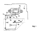
- Figure 1 shows, inside an electrical protecting device, the part where the polarised relay 10 is placed; said relay 10 fixed to stand 12 has a pusher 11.
- tip 16 this latter disconnects hooking means 17 which switches on the whole disconnecting apparatus 18.
- Figure 2 shows a first embodiment of the present invention automatically checked by a C.P.A., when no free space is available inside the protecting device.
- the lever 13 of figure 1 is split into two half-levers 20, 21 hinged on the same axis 14, being said two half-levers 20, 21 integral to each other during the normal service working as only one lever 13 previously described.
- figure 2 which is an exploded view
- figure 3 which is a horizontal section A-A along the centre line of axis 14, one of said half-levers 20, 21, e.g. half-lever 20, is integrally fixed to axis 14 by means of two suitable stops 22, 23; when axis 14 shifts forward and backward it trails half-lever 20, whereas half-lever 21 stops because of bush 24 which binds said half-lever 21 to stand 12.
- tailpiece 27 of half-lever 20, which up to this point engaged half-lever 21 making it integral to said half-lever 20 during its possible clockwise rotation, is placed in correspondence to free space 28 of half-lever 21; in this position the two half-levers 20, 21 are now free.
- the C.P.A. sends an impulse to the relay 10, said impulse being as strong as the one produced by a failure in the plant with a consequent coming out of pusher 11 which causes a counter-clockwise rotation of half-lever 20, whereas half-lever 21 and hooking means 17 (not represented in Figs. 2-3) stop and then stops also the main mechanism which operates the network contacts.
- half-lever 20 operates a suitable contact 29 by means of its arm 30, said contact 29 being represented in figure 2 as a mechanical one, but may be reed-type or static ones.
- a signal is generated and sent to the C.P.A. causing the excitement of a second electro-magnet 31 which provokes, by means of spring 32, a counter-rotation of half-lever 20 with its slide 33 towards the starting position and further, in order to make sure that through the aforesaid half-lever 20 also pusher 11 of the relay 10 reaches its starting point.
- the C.P.A. After checking the efficiency of the differential trasformer, of the failure detector (relay) and of the first operating unit of the disconnecting apparatus, the C.P.A. resets and starts a new delay cycle, at the end of which it checks again and so on, till when, during such an automatic check, it happens that the relay 10, although energized by means of a test impulse, does not activate pusher 11. It is obvious that the protecting apparatus fails because the relay is no longer efficient or because the mechanical frictions have increased, or because oxidation or corrosion occurs, or because the anchor of the magnetic circuit of the relay 10 adheres, etc.
- Figure 2 shows a particular embodiment of two half-levers 20 and 21, linked by means of any mechanical device, e.g. a pin or a lock placed in suitable bores on parallel side walls of half-levers 20 and 21.
- any mechanical device e.g. a pin or a lock placed in suitable bores on parallel side walls of half-levers 20 and 21.
- the placement of said pin corresponds to the normal working of the device, whereas the extraction of said pin by means of an electro-magnet commanded by the C.P.A. makes the two half-levers 20 and 21 free to indipendently move.
- the aforesaid linkage could be carried out by means of any other device, electro-magnetic (e.g. an electro-magnetical coupling), magnetic (e.g. one or more permanent magnets suitably disposed by an external operator), hydraulic or pneumatical (e.g. by means of a little pinion commanded by an electro-valve), the working of said means being always controlled by the C.P.A
- figure 4 shows a flow-chart of the C.P.A., which in its turn represents a well-known technique, namely:
- the check of a regular working can be effected in a very short while (around 2 seconds).
- the lapse between two checks may vary from some seconds to one month, according to the apparatus, its functions and its requirements.
- Figure 5 shows a second embodiment of the device according to the present invention.
- a free space is available inside the apparatus and it is necessary an alteration to the normal mechanism of figure 1.
- the relay 10 is fixed on one side to the axis 51 around which it could rotate, were it not stopped by spring 52. If, on the contrary, the external electro-magnet 53 is energized when the C.P.A. decides to start the periodical check, the relay 10 is called back by the anchor of electro-magnet 53 through tie 54 and rotates around axis 51 thus pushing pusher 11 outside the field of action of arm 55 of disconnecting lever 13.
- the relay 10 If, in this new position, the relay 10 is energized by means of the C.P.A., pusher 11 engages lever 56 by making it rotate around axis 57 with an angle sufficient to set in motion a contact, both a metallic contact 58 or a static one.
- the consent signal reported by contact 58 to the C.P.A. starts the following step which consists of loading lever 56 by energizing electro-magnet 59 which swallows up its mobile core and of re-starting the protection by ordering the de-energization of electro-magnet 53 which makes come back the relay 10 to its starting position.
- step which consists of loading lever 56 by energizing electro-magnet 59 which swallows up its mobile core and of re-starting the protection by ordering the de-energization of electro-magnet 53 which makes come back the relay 10 to its starting position.
- pusher 11 had not come out when the C.P.A. had sent the electric impulse to the disconnecting device 10
- lever 56 would have not rotate and contact 58 would have not switched on.
- Receiving no signal the C.P.A. would have stopped and would have started the foreseen emergency measures.
- the showed embodiment is valid in all cases, namely if the relay 10 does not rotate, but shifts or is lifted, if its motion is a combined rotation and shifting or if the relay is definite while the disconnecting chain partly rotates or shifts.
- the third embodiment of the present invention which manually works, is described as follows with a particular reference to a residual current circuit breaker; however, with obvious adjustments, this system can also apply to other electrical apparatuses to keep under control.
- the test button releases a half-lever thus verifying the detecting and disconnecting function (differential transformer, relay and disconnecting chain) without interrupting the supply, as hereinafter described with reference to figures 6 and 7.
- the button is marked with 60.
- the button upper part 61 protruding out of the breaker carter is pushed by the user.
- Letter T 62 graved on said button upper part 61 is prescribed by the rules and means "test”.
- 63 and 64 are two button side wings, which, shifting along the two fixed grooves of the switch, lead the button in its shifting downwards.
- the button cylindrical lower part 66 which can shift inside the sleeve 67, integral to the breaker, guides the reaction spring 68.
- axis 14 shifts rightwards by means of an external action on its left end and comes back to its starting position thanks to spring 34.
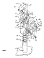
- Figure 6 shows as the pressure on the button shifts the aforesaid axis 14.
- the bent part 69 is to be noticed, to which the fixed axis 70 is integral; the free lever 71 is hinged on said axis 70, said lever being frictionally pressed by spring 72 and stop 73.
- the upper end of lever 71 can be placed by the user either on the free space 74, comprised in the main body of the switch corresponding to: “Check without switch click", or on the contiguous space 75, corresponding to "Check with switch click".
- lever 71 is provided with a tailpiece 76 compelling cam 77 (free to rotate on axis 93 integral to button 60), to stop in the position indicated in figure 6, when lever 71 is placed in the free space 74.
- arm 79 and its end 81 will come back to their starting position thus leading upwards also half-lever 20 which will press on the pusher 11 re-energizing the relay 10.
- the end 81 has a springy tailpiece 82, on which the lower end of tailpiece 78 shifts when axis 14, because of spring 34, brings back half-lever 20 to its usual rest position, namely integral to lever 21, cam 77 being come back to the position of figure 6.
- button 60 The electrical functions performed by button 60 in the meanwhile are reported in figure 7, which shows said button 60 rotated 90° counter-clockwise in order to clear up said functions.
- Said test current generates a current in the secondary winding 39 of transformer 38 which energizes the relay 10 and draws out pusher 11 of figure 2, thus rotating counter-clockwise lever 20, which, in the meantime, had been shifted rightwards by axis 14 pushed in its turn by cam 77 of figure 6, and is released from half-lever 21.
- Arm 30 of half-lever 20 switches on contacts 83, 84 which, in their turn, switch on the circuit of lamp 89 which lights up, thus confirming to the user that the differential transformer, the relay and the first half-lever work correctly.
- the breaker could also be provided with a timer programmed with delays corresponding to one month, or to a different lapse of time in case of particular necessities; at the expiry of the programmed time said timer lights up a visual signal, or an acustic one, which indicates to the user that he must press the test button.
- lever 71 If the user wishes to check all functions of the switch, he just has to move lever 71 from position 74 to position 75. In this case, in fact, the tailpiece 76 of lever 71 goes away from cam 77 which, during the pressure of the finger on button 60 shifts to the end of axis 14 without moving it and then leaving the two half-levers 20, 21 integral to each other.
Landscapes
- Emergency Protection Circuit Devices (AREA)
- Testing Electric Properties And Detecting Electric Faults (AREA)
- Mechanisms For Operating Contacts (AREA)
Claims (10)
- Einrichtung zum automatischen oder manuellen Testen der Leistungsfähigkeit der empfindlichsten Komponenten eines elektrischen Geräts, insbesondere eines Reststrom-Stromkreisabschalters, die die Kontakte des Hauptstromkreises auch im Falle einer Testbedingung im Normalbetriebszustand hält und einen Hebel umfaßt, der die Bewegung des Stößels eines zum elektrischen Gerät gehörenden Relais auf Einhakmittel überträgt, die den Abschaltmechanismus des Abschalters sperren,
wobei diese Einrichtung dadurch gekennzeichnet ist,
daß der Hebel (13) in Form zweier Halbhebel (20, 21) doppelt ausgelegt ist; daß der Stößel (11) auf einen ersten (20) der beiden Halbhebel (20, 21) einwirkt; daß die Einrichtung Mittel zum automatischen oder manuellen Injizieren eines simulierten Fehlerstroms enthält, der die Operation des Geräts unter Test veranlaßt; und daß im Falle einer Testbedingung der erste Halbhebel (20) vom zweiten Halbhebel (21) getrennt wird, um die Übertragung der Bewegung vom Stößel (11) zum Einhakmittel (17) zu verhindern, wogegen im Falle der Normalbetriebsbedingung die Halbhebel (20, 21) miteinander vollständig verbunden sind. - Einrichtung nach Anspruch 1,
dadurch gekennzeichnet,
daß der Hebel (13) in Form zweier Halbhebel (20, 21) doppelt ausgelegt ist, die an der gleichen Achse (14) schwenkbar angebracht sind, jedoch zwei mögliche gegenseitige Positionen haben:(a) eine erste Position, die dem Normalbetriebszustand ohne Einwirkung äußerer Wirkkräfte entspricht, wobei die beiden Halbhebel (20, 21) miteinander vereint sind und somit einen einzigen Hebel bilden, der drehen kann, wobei der Abschaltmechanismus freigegeben und das Abschalten des Schalters gesteuert wird;(b) eine zweite Position der beiden Halbhebel (20, 21), die durch die Einwirkung äußerer Wirkkräfte verursacht wird, wenn die Unterbrechung des Sperrmechanismus erwünscht ist, wobei die zweite Position durch Verschieben der Achse (14) der beiden Halbhebel (20, 21) erhalten wird, so daß sich der ziehende Halbhebel (20) vollständig mit der Achse (14) wegen zweier Anschläge (22, 23) an dieser Achse (14) verschiebt, wohingegen der gezogene Halbhebel (21) stehenbleibt, weil er mit dem Gestell (12) verbunden ist und hinsichtlich der Achse (14) frei ist; aufgrund der Verschiebung der Achse (14) ist das Endstück (27) des ziehenden Halbhebels innerhalb eines freien Raumes (28) des gezogenen Halbhebels (21) und dann, während des Tests, kann der Stößel (11) des Relais diesen Halbhebel (20) frei drehen, bis ein Kontakt (29) eingeschaltet wird, der bestätigt, daß das Schutzsystem leistungsfähig ist, wogegen der andere Halbhebel (21) und der Einhakmechanismus im Stillstand sind. - Einrichtung nach Anspruch 1,
dadurch gekennzeichnet,
daß die Verbindung zwischen den beiden Halbhebeln (20, 21) mittels einer Nadel oder eines Riegels ausgeführt ist, die/der in passende Bohrungen eingeführt ist, die an Seitenwänden der beiden Halbhebel angeordnet sind, die nur dann voneinander unabhängig werden können, wenn eine äußere Wirkkraft, wie ein Elektromagnet, die Nadel oder den Riegel von wenigstens einem der Halbhebel entfernt. - Einrichtung nach Anspruch 1,
dadurch gekennzeichnet,
daß zwei Halbhebel (20, 21) miteinander über magnetische Mittel vereint sind. - Einrichtung nach Anspruch 1,
dadurch gekennzeichnet,
daß zwei Halbhebel (20, 21) während des Normalbetriebszustands miteinander vereint sind, wogegen sie während des Tests mittels hydraulischer oder pneumatischer Einrichtungen, die bei den Halbhebeln angebracht und extern geführt werden, voneinander unabhängig werden. - Einrichtung nach Anspruch 1,
dadurch gekennzeichnet,
daß die Unterbrechung der Abschaltkette durch Drehung oder/und Verschiebung des Relais (10) mittels einer externen Einrichtung (52, 53, 54) erhalten wird, so daß das Relais (10) während des Tests eine unterschiedliche Position erreicht, in der der Stößel (11) des Relais (10) einen Hebel (56) betätigt, um den Kontakt (58) einzuschalten, der die Schutzwirksamkeit bestätigt. - Einrichtung nach Anspruch 2,
gekennzeichnet durch
die Zusammensetzung aus einem von außen manuell zu drükkenden Knopf (60), der außer den elektrischen Kontakten, die zum Injizieren eines simulierten, die Operation des Geräts bei Kontrolle veranlassenden Fehlerstroms nötig sind, einen Nocken (77) trägt, der geeignet ist, eine Achse (14) zu verschieben, die ihrerseits einen Halbhebel (20) zur Drehung an dieser Achse (14) freischiebt und die nach dieser Verschiebung ihre Verbindung zu einem zweiten Halbhebel (21) verliert. - Einrichtung nach Anspruch 7,
dadurch gekennzeichnet,
daß der Nocken (77), der die Verschiebung der Achse (14) veranlaßt, an der beide Halbhebel (20, 21) drehen, in seiner für den Knopf (60) relevanten Position durch einen am festen Teil des Gerätes schwenkbar gelagerten Hebel (71) verriegelt ist, der unter Gleiten an einer Seite des Nockens (77) ihn in seiner Position bindet, sogar wenn sich der gedrückte Knopf (60) verschiebt, wobei der erwähnte Hebel (71) zwei stabile Positionen hat, von denen die eine die vorher erwähnte ist und die andere in bezug auf die erste um einen beliebigen Winkel gedreht ist, der ihn vom Nocken (77) löst und ihn dann nicht länger verbindet, so daß der Knopf (60) jede beliebige andere Funktion ausführen kann, außer derjenigen, welche der Nocken (77) zu verrichten hat. - Einrichtung nach Anspruch 7,
dadurch gekennzeichnet,
daß sie mit einfachen Mitteln versehen ist, um aufeinanderfolgend zwei elektrische Stromkreise zu betätigen, wobei der eine der Stromkreis einer Signalisierungslampe (89) ist und der andere geeignet ist, einen Fehlerstrom zu simulieren, wobei die Stromkreise mit den vorher beschriebenen mechanischen Vorgängen synchronisiert sind. - Einrichtung nach den vorhergehenden Ansprüchen 7, 8, 9,
dadurch gekennzeichnet,
daß der Knopf (60) durch ein beliebiges anderes Stellglied (z.B. Hebel oder Drehknopf) ersetzt ist und auf irgendeine Weise ausgeführt und betätigt wird.
Applications Claiming Priority (4)
| Application Number | Priority Date | Filing Date | Title |
|---|---|---|---|
| IT001332 IT1264863B1 (it) | 1993-06-22 | 1993-06-22 | Dispositivo che a periodi di tempo prefissati e senza interrompere il servizio effettua automaticamente la diagnosi dell'efficienza delle parti piu' importanti di e/o piu' delicate di una apparecchiatura elettrica di protezione o di comando o di segnalazione |
| ITMI931332 | 1993-06-22 | ||
| ITMI932581 | 1993-12-06 | ||
| IT93MI002581A IT1265388B1 (it) | 1993-12-06 | 1993-12-06 | Dispositivo manuale per provare l'efficienza dei componenti a maggior rischio di guasto di un'apparecchiatura elettrica, in particolare di |
Publications (3)
| Publication Number | Publication Date |
|---|---|
| EP0632477A2 EP0632477A2 (de) | 1995-01-04 |
| EP0632477A3 EP0632477A3 (de) | 1995-11-22 |
| EP0632477B1 true EP0632477B1 (de) | 1999-08-11 |
Family
ID=26331009
Family Applications (1)
| Application Number | Title | Priority Date | Filing Date |
|---|---|---|---|
| EP94109177A Expired - Lifetime EP0632477B1 (de) | 1993-06-22 | 1994-06-15 | Einrichtung zum automatischen oder manuellen Testen eines Schutz-, Steuer- oder Meldegeräts |
Country Status (3)
| Country | Link |
|---|---|
| EP (1) | EP0632477B1 (de) |
| AT (1) | ATE183333T1 (de) |
| DE (1) | DE69419985T2 (de) |
Families Citing this family (2)
| Publication number | Priority date | Publication date | Assignee | Title |
|---|---|---|---|---|
| ITMI20062032A1 (it) * | 2006-10-23 | 2008-04-24 | Gewiss Spa | Interruttore differenziale |
| FR3057389B1 (fr) * | 2016-10-11 | 2020-12-25 | Schneider Electric Ind Sas | Appareillage de coupure electrique differentiel comportant un dispositif de test de la fonction differentielle |
Family Cites Families (3)
| Publication number | Priority date | Publication date | Assignee | Title |
|---|---|---|---|---|
| US4152683A (en) * | 1977-07-20 | 1979-05-01 | Gould Inc. | Test means for circuit breaker automatic trip mechanism |
| AT384906B (de) * | 1985-12-02 | 1988-01-25 | Felten & Guilleaume Ag Oester | Fehlerstrom- und leitungsschutzschalter |
| US4713639A (en) * | 1987-02-20 | 1987-12-15 | Westinghouse Electric Corp. | Circuit breaker with push-to-trip button and trip bar |
-
1994
- 1994-06-15 AT AT94109177T patent/ATE183333T1/de active
- 1994-06-15 DE DE69419985T patent/DE69419985T2/de not_active Expired - Lifetime
- 1994-06-15 EP EP94109177A patent/EP0632477B1/de not_active Expired - Lifetime
Also Published As
| Publication number | Publication date |
|---|---|
| DE69419985T2 (de) | 2000-01-27 |
| EP0632477A2 (de) | 1995-01-04 |
| EP0632477A3 (de) | 1995-11-22 |
| ATE183333T1 (de) | 1999-08-15 |
| DE69419985D1 (de) | 1999-09-16 |
Similar Documents
| Publication | Publication Date | Title |
|---|---|---|
| CA1217804A (en) | Remote controlled circuit breaker | |
| EP1950784B1 (de) | Rückstellvorrichtung für eine elektrische Sicherheitsvorrichtung mit reduzierter Rückstellzeit | |
| EP1449287B1 (de) | Steuer und schutzmodul eines schaltgeräts | |
| MX9604381A (es) | Dispositivo de control y señalizacion para conmutador de proteccion. | |
| FI70756B (fi) | Kontaktorapparat omfattande organ foer automatiskt oeppnande av kraftkretsar och en lokal styranordning | |
| NL8503161A (nl) | Uitschakelinrichting voor op afstand bediende opening en sluiting van zijn circuits. | |
| KR20180110532A (ko) | 회로차단기의 전기적 인터록 회로 | |
| EP1912241B1 (de) | Elektrische Sicherungsvorrichtung | |
| US4473860A (en) | Contactor apparatus comprising automatic opening means and a local control member | |
| EP0632477A2 (de) | Einrichtung zum automatischen oder manuellen Testen eines Schutz-, Steuer- oder Meldegeräts | |
| US7760055B2 (en) | Method and device for the secure operation of a switching device | |
| EP0258198B1 (de) | Elektrische Schutzvorrichtung | |
| US6307455B1 (en) | Control mechanism for a circuit breaker | |
| CN120376366A (zh) | 磁通脱扣器、隔离开关以及供电系统 | |
| CZ296254B6 (cs) | Zarízení pro indikaci elektrické poruchy v prerusovacím zarízení, napríklad diferenciálním spínaci,a spínací prístroj vybavený tímto zarízením | |
| US2025653A (en) | Circuit breaker apparatus | |
| GB2204736A (en) | Residual current circuit breakers for sockets | |
| US4010457A (en) | Overload protection device | |
| EP0048042A2 (de) | Sicherheitsvorrichtung für Schalter mit Federantrieb, die fahrbar in einer Zelle sind | |
| SU1105956A1 (ru) | Пускатель-автомат | |
| AU2005256715B2 (en) | Control device for an electrical apparatus | |
| EP0550927B1 (de) | Selektiver automatischer Sicherheitsschalter | |
| GB2086136A (en) | Improvements in and relating to earth leakage circuit breakers | |
| GB2565304A (en) | A bistable electrical switching device | |
| IT1264863B1 (it) | Dispositivo che a periodi di tempo prefissati e senza interrompere il servizio effettua automaticamente la diagnosi dell'efficienza delle parti piu' importanti di e/o piu' delicate di una apparecchiatura elettrica di protezione o di comando o di segnalazione |
Legal Events
| Date | Code | Title | Description |
|---|---|---|---|
| PUAI | Public reference made under article 153(3) epc to a published international application that has entered the european phase |
Free format text: ORIGINAL CODE: 0009012 |
|
| AK | Designated contracting states |
Kind code of ref document: A2 Designated state(s): AT BE DE FR |
|
| PUAL | Search report despatched |
Free format text: ORIGINAL CODE: 0009013 |
|
| AK | Designated contracting states |
Kind code of ref document: A3 Designated state(s): AT BE DE FR |
|
| 17P | Request for examination filed |
Effective date: 19960424 |
|
| 17Q | First examination report despatched |
Effective date: 19980429 |
|
| GRAG | Despatch of communication of intention to grant |
Free format text: ORIGINAL CODE: EPIDOS AGRA |
|
| GRAG | Despatch of communication of intention to grant |
Free format text: ORIGINAL CODE: EPIDOS AGRA |
|
| GRAH | Despatch of communication of intention to grant a patent |
Free format text: ORIGINAL CODE: EPIDOS IGRA |
|
| GRAH | Despatch of communication of intention to grant a patent |
Free format text: ORIGINAL CODE: EPIDOS IGRA |
|
| GRAA | (expected) grant |
Free format text: ORIGINAL CODE: 0009210 |
|
| AK | Designated contracting states |
Kind code of ref document: B1 Designated state(s): AT BE DE FR |
|
| REF | Corresponds to: |
Ref document number: 183333 Country of ref document: AT Date of ref document: 19990815 Kind code of ref document: T |
|
| REF | Corresponds to: |
Ref document number: 69419985 Country of ref document: DE Date of ref document: 19990916 |
|
| ET | Fr: translation filed | ||
| PLBE | No opposition filed within time limit |
Free format text: ORIGINAL CODE: 0009261 |
|
| STAA | Information on the status of an ep patent application or granted ep patent |
Free format text: STATUS: NO OPPOSITION FILED WITHIN TIME LIMIT |
|
| 26N | No opposition filed | ||
| PGFP | Annual fee paid to national office [announced via postgrant information from national office to epo] |
Ref country code: DE Payment date: 20120622 Year of fee payment: 19 |
|
| PGFP | Annual fee paid to national office [announced via postgrant information from national office to epo] |
Ref country code: FR Payment date: 20120705 Year of fee payment: 19 |
|
| PGFP | Annual fee paid to national office [announced via postgrant information from national office to epo] |
Ref country code: BE Payment date: 20120621 Year of fee payment: 19 |
|
| PGFP | Annual fee paid to national office [announced via postgrant information from national office to epo] |
Ref country code: AT Payment date: 20120613 Year of fee payment: 19 |
|
| BERE | Be: lapsed |
Owner name: *ABB ELETTROCONDUTTURE S.P.A. Effective date: 20130630 |
|
| REG | Reference to a national code |
Ref country code: AT Ref legal event code: MM01 Ref document number: 183333 Country of ref document: AT Kind code of ref document: T Effective date: 20130615 |
|
| REG | Reference to a national code |
Ref country code: FR Ref legal event code: ST Effective date: 20140228 |
|
| PG25 | Lapsed in a contracting state [announced via postgrant information from national office to epo] |
Ref country code: BE Free format text: LAPSE BECAUSE OF NON-PAYMENT OF DUE FEES Effective date: 20130630 |
|
| REG | Reference to a national code |
Ref country code: DE Ref legal event code: R119 Ref document number: 69419985 Country of ref document: DE Effective date: 20140101 |
|
| PG25 | Lapsed in a contracting state [announced via postgrant information from national office to epo] |
Ref country code: DE Free format text: LAPSE BECAUSE OF NON-PAYMENT OF DUE FEES Effective date: 20140101 |
|
| PG25 | Lapsed in a contracting state [announced via postgrant information from national office to epo] |
Ref country code: FR Free format text: LAPSE BECAUSE OF NON-PAYMENT OF DUE FEES Effective date: 20130701 Ref country code: AT Free format text: LAPSE BECAUSE OF NON-PAYMENT OF DUE FEES Effective date: 20130615 |