EP0632606A1 - Verfahren und Gerät zur Erstellung und zum Erhalten der Rahmensynchronisation in einer Satelliten Kommunikationsanordnung - Google Patents
Verfahren und Gerät zur Erstellung und zum Erhalten der Rahmensynchronisation in einer Satelliten Kommunikationsanordnung Download PDFInfo
- Publication number
- EP0632606A1 EP0632606A1 EP94110233A EP94110233A EP0632606A1 EP 0632606 A1 EP0632606 A1 EP 0632606A1 EP 94110233 A EP94110233 A EP 94110233A EP 94110233 A EP94110233 A EP 94110233A EP 0632606 A1 EP0632606 A1 EP 0632606A1
- Authority
- EP
- European Patent Office
- Prior art keywords
- signal
- providing
- demodulated
- unique word
- power
- Prior art date
- Legal status (The legal status is an assumption and is not a legal conclusion. Google has not performed a legal analysis and makes no representation as to the accuracy of the status listed.)
- Granted
Links
- 238000004891 communication Methods 0.000 title claims abstract description 54
- 238000000034 method Methods 0.000 title claims abstract description 20
- 238000001514 detection method Methods 0.000 claims abstract description 35
- 230000002401 inhibitory effect Effects 0.000 claims description 8
- 238000012935 Averaging Methods 0.000 claims 6
- 230000005540 biological transmission Effects 0.000 description 9
- 238000010586 diagram Methods 0.000 description 7
- 230000010363 phase shift Effects 0.000 description 5
- 238000012545 processing Methods 0.000 description 4
- 238000005070 sampling Methods 0.000 description 4
- 239000003112 inhibitor Substances 0.000 description 3
- 230000008569 process Effects 0.000 description 3
- 230000001360 synchronised effect Effects 0.000 description 3
- 238000012937 correction Methods 0.000 description 2
- 238000012986 modification Methods 0.000 description 2
- 230000004048 modification Effects 0.000 description 2
- 230000002411 adverse Effects 0.000 description 1
- 230000003466 anti-cipated effect Effects 0.000 description 1
- 230000002238 attenuated effect Effects 0.000 description 1
- 230000001934 delay Effects 0.000 description 1
- 230000001419 dependent effect Effects 0.000 description 1
- 238000011017 operating method Methods 0.000 description 1
- 230000008054 signal transmission Effects 0.000 description 1
- 238000012546 transfer Methods 0.000 description 1
- 230000009466 transformation Effects 0.000 description 1
Images


Classifications
-
- H—ELECTRICITY
- H04—ELECTRIC COMMUNICATION TECHNIQUE
- H04B—TRANSMISSION
- H04B7/00—Radio transmission systems, i.e. using radiation field
- H04B7/14—Relay systems
- H04B7/15—Active relay systems
- H04B7/204—Multiple access
- H04B7/212—Time-division multiple access [TDMA]
- H04B7/2125—Synchronisation
-
- H—ELECTRICITY
- H04—ELECTRIC COMMUNICATION TECHNIQUE
- H04L—TRANSMISSION OF DIGITAL INFORMATION, e.g. TELEGRAPHIC COMMUNICATION
- H04L7/00—Arrangements for synchronising receiver with transmitter
- H04L7/04—Speed or phase control by synchronisation signals
- H04L7/041—Speed or phase control by synchronisation signals using special codes as synchronising signal
- H04L7/042—Detectors therefor, e.g. correlators, state machines
-
- H—ELECTRICITY
- H04—ELECTRIC COMMUNICATION TECHNIQUE
- H04L—TRANSMISSION OF DIGITAL INFORMATION, e.g. TELEGRAPHIC COMMUNICATION
- H04L7/00—Arrangements for synchronising receiver with transmitter
- H04L7/0054—Detection of the synchronisation error by features other than the received signal transition
- H04L7/007—Detection of the synchronisation error by features other than the received signal transition detection of error based on maximum signal power, e.g. peak value, maximizing autocorrelation
Definitions
- the present invention relates to a method and apparatus for establishing and maintaining frame synchronization in a mobile satellite communication system, and more particularly, for establishing and maintaining frame synchronisation on the basis of unique word (UW) detection to prevent erroneous operation due to shadowing phenomena occurring on the transmission path.
- UW unique word
- FEC forward error correction
- C/N carrier-power to noise-power
- the rate at which the frames of the communication signal are transmitted by the satellite or stations must be synchronized with the rate at which such frames are detected by the satellite or station.
- Such frame synchronization can typically be accomplished by using a unique word (UW)in a preamble added to the initial portion of a burst signal, or unique words periodically provided in frames of the signal.
- UW unique word
- the unique word or words used for frame synchronisation can also be used to resolve phase ambiguity of the communication signal, or identify a satellite channel.
- Fig. 9 illustrates a block diagram of a conventional frame synchronization system.
- the received modulated signals are supplied to a demodulator 1 and demodulated into baseband demodulated signals.
- the demodulated signals are supplied to a UW detector 6, where a unique word UW is detected from the demodulated signals.
- a frame synchronizing circuit 7 sets the timing for receiving the frames based on a predetermined, prestored frame format corresponding to the detected UW.
- An aperture generator 8 controls the detection aperture of the UW detector 6 in accordance with the output signal of the frame synchronizing circuit 7.
- the aperture of the UW detector 6 is the time period that the UW detector remains "open" to detect the communication signal.
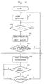
- the UW detector 6, frame synchronising circuit 7 and aperture generator 8 cooperate to establish frame synchronization by the procedure shown in the flow chart of Fig. 10. That is, in steps 101 and 102 of the frame synchronization process, the UW detector 6 remains "open” to receive the communication signal until it detects an initial unique word in the communication signal.
- UW detectors of this type are described, for example, in "TDMA Communication” by Heiichi Yamamoto et al., a 1989 publication by the Institute of Electronics, Information and Communication Engineers, and "Elements of Digital Satellite Communication Volume 1" by W.W. Wu which was published in 1984 by Computer Science Press.
- step 103 when the UW detector 6 detects a unique word UW in the communication signal, the UW detector provides a signal to the frame synchronizing circuit 7, which sets the timing for receiving frames in the communication signal based on a predetermined frame format corresponding to the detected unique word UW.
- the frame synchronizing circuit 7 also controls the UW detector 6 via the aperture generator 8 to detect unique words in narrow apertures, that is, during short time periods.
- the timing at which frames are received is established by setting the receive frame counter of the frame synchronising circuit 7, which counts periods during which frames are received.
- the count of the receive frame counter is used as the time reference for various functions synchronized with received frames.
- the position in the communication signal of that next unique word is estimated based on the receive frame timing.
- the aperture generator 8 thus generates an aperture signal according to that position, and permits the UW detector to detect a unique word only during that time period designated by the aperture signal.
- the aperture generator 8 continues to generate a series of aperture signals to enable the UW detector to detect subsequent unique words UW in the communication signal. Then, to assure that frame synchronization is occurring based on the unique words in the communication signal, in step 104, it is determined whether unique words are detected "I" consecutive times with this narrow aperture (brief time period). Unless unique words have been detected I consecutive times, the processing returns to step 101, and repeats. When it is determined that unique words have been detected "I" consecutive times, in step 105, it is determined that frame synchronisation has been established.
- step 106 the UW detector 6 is controlled by the frame synchronizing circuit 7 and aperture generator 8 to continue detecting unique words during the same apertures (time periods) to maintain frame synchronization. However, if at any time during the UW detection process, the UW detector 6 does not detect unique words for "J" consecutive times (i.e. "J" consecutive aperture time periods), it is determined that frame synchronization has been lost. Accordingly, the processing returns to step 101 and is repeated as described above.
- the value "J” is used to assure that frame synchronization actually has been lost before the processing is repeated. That is, after frame synchronisation has been established, if the UW detector 6 fails to detect a unique word during, for example, only one aperture period, frame synchronization is not considered to be lost. However, if the UW detector 6 fails to detect unique words during "J" consecutive aperture periods, synchronization is presumed to have been lost, and thus, the process of Fig. 10 is repeated to resynchronize the timing of the communication.
- the values of "I” and “J” usually depend on the type of satellite communication systems being operated. “I” is typically equal to any number from 2 to 4, and “J” is typically equal to any number from 2 to 6.
- the conventional frame synchronisation system detects UW's and establishes and maintains synchronization between the transmission and receipt of the frames in the communication signal according to the number of consecutive times that the UW detector detects or fails to detect unique words.
- the conditions of the transmission paths for mobile satellite communication stations used differ from those of fixed satellite communication stations.
- the communication signals are subject to a shadowing phenomena caused by buildings, terrain, and other objects which may interfere with the signal transmission.
- the conventional system merely estimates the position of the unique words in the communication signal after a first unique word is received.
- the frame synchronization is determined based on unique word detection irrespective of whether the actual communication signal continues to be received.
- the system may erroneously interpret portions of noise signals to be unique words when the actual communication signals have been interrupted.
- the system may erroneously set the timing of the receipt of the frames based on these erroneous unique words.
- the aperture times of the UW detector 6 may be widened (i.e the time periods during which the UW detector detects unique words are increased) to compensate for the lag in frame timing after the shadowing phenomenon and/or modulation timing errors occur.
- the aperture size (time period) is increased, the rate of false unique word detection also may increase.
- the frame timing may become erroneous.
- any erroneous unique words cause the phase of the communication signal to be erroneously determined. Hence, it may be impossible for the phase to be determined correctly.
- the present invention provides a frame synchronization system for an apparatus which receives a modulated signal obtained by digital phase shift keying of a carrier wave with digital signals having frames. A unique word and data are multiplexed in each of the frames.
- An embodiment of the system of the present invention comprises a demodulator for demodulating the modulated signal which has been received, and a signal detecting device for detecting the presence or absence of the demodulated signal. That is, the signal detecting device determines if the power of the demodulated signal is at least equal to a threshold level.
- the signal detecting device indicates that an actual demodulated communication signal is present. However, if the power of the demodulated signal is below the threshold level, the signal detecting device indicates that no actual demodulated communication signal is present.
- a selector of the system selects, according to the output detection signal of the signal detecting device, either the demodulated signal output by the demodulator or fixed data different from the unique word. That is, when the power of the demodulated signal is at least equal to the threshold level, the selector selects and outputs the demodulated signal. However, when the power of the demodulated signal is less than the threshold level, the selector selects and outputs the fixed data.
- the system further comprises a unique word detector, coupled to the selector, which detects the unique word from the demodulated signal when the selector provides the demodulated signal to the unique word detector.
- a unique word detector coupled to the selector, which detects the unique word from the demodulated signal when the selector provides the demodulated signal to the unique word detector.
- the selector provides the fixed data to the unique word detector, the unique word detector cannot mistake the fixed data with a unique word and therefore does not detect a unique word.
- the unique word detector provides the detected unique word to a frame synchronizing circuit which establishes frame synchronization based on the detected unique word. Hence, when no unique word is detected (e.g when the fixed data is provided to the unique word detector), the frame synchronising circuit will not establish frame synchronization.
- the system further comprises an aperture generator, controlled by the frame synchronizing circuit, which generates an aperture signal that controls the unique word detector. That is, the aperture signal indicates the time period that the unique word detector is to be open to detect a unique word in the frame. Hence, the unique word detector will only detect unique words during an aperture period. The aperture detector thus generates successive aperture signals to enable the unique word detector to detect unique words in successive frames.
- the selection circuit is removed, and an inhibitor circuit is coupled between the unique word detector and the frame synchronization circuit.
- the inhibitor circuit When the power of the demodulated signal is at least equal to the threshold level, the inhibitor circuit outputs the detected unique word to the frame synchronization circuit. Hence, the frame synchronization circuit will establish frame synchronization.
- the inhibitor circuit inhibits the detected unique word from being output to the frame synchronization circuit. Hence, the frame synchronization circuit will not establish frame synchronization.
- Fig. 1 is a block diagram of an embodiment of a frame synchronization system of the present invention. Items which are the same as those shown in Fig. 9 are identified by corresponding reference numerals.
- Fig. 1 is an example of a mobile earth station of a mobile satellite communication system, in which communication signals are received and demodulated by a demodulator 1.
- These received communication signals include, for example, digital signals of a modulated signal generated, for example, by phase shift keying (PSK) of the carrier.
- PSK phase shift keying
- the digital signals have a predetermined frame format such as that shown in Fig. 2.
- one frame consists of 240 symbols. These 240 symbols include a unique word UWm (where "m" is 1, 2, 3 or 4) and data Dm, which are multiplexed on a time division basis.
- UWm unique word
- Dm data
- Four frames constitute each transmission unit.
- the number of symbols in each frame and the number of frames in each transmission unit can vary as desired.
- the amount of unique words can vary in accordance with the amount of frames per transmission unit.
- the transmission rate may be, for example, 4,000 baud, at which 240 symbols are transmitted in 60 ms. However, any suitable baud rate may be used.
- the unique words UW1 through UW4 are determined by the autocorrelation of each unique word with front and back sequency and the cross-correlation between unique words, or in accordance with the Hamming distance.
- the modulated signal is quadrature phase shift keying (QPSK)
- the unique word consists of 24 bits total with "0001 0111 1101” being in the "I” (in-phase) signal and "0011 0100 0110” being in the "Q” (quadrature) signal.
- the modulated signal is binary phase shift keying (BPSK)
- BPSK binary phase shift keying
- it has, for example, a fixed 32-bit pattern of "0100 1000 0101 0111 0110 0011 1110 0110".
- any suitable bit amount or pattern may be used.
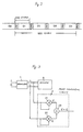
- the output demodulated signal of the demodulator 1 is supplied to a power calculating circuit 2 and to selector circuit 5.
- the power calculating circuit 2 together with a low-pass filter 3 and decision circuit 4, comprise the signal detecting circuit 9.
- the power calculating circuit 2 has a circuit configuration comprising, for example, as illustrated in Fig. 3, a first multiplier 21, a second multiplier 22 and an adder 23.
- the first multiplier 21 squares the in-phase component r l of the demodulated signal provided from the demodulator 1, and the second multiplier 22 squares the quadrature component r Q of the demodulated signal.
- Adder 23 adds these squared signals output from the multipliers 21 and 22, and thus outputs an addition signal represented by (r2 l + r2 Q ).
- This addition signal has a level corresponding to the signal power (actually, the sum of the signal power and the noise power).
- the low-pass filter 3 which averages said signal power, has a circuit configuration comprising, for example, a first multiplier 31, an adder 32, a delaying circuit 33 and a second multiplier 34.
- the first multiplier 31 multiplies the addition signal provided from the power calculating circuit 2 by a constant ⁇ .
- the adder 32 adds the output signals of the multipliers 31 and 34.
- the delaying circuit 33 delays the input signal by one sampling period.
- the second multiplier 34 multiplies by a constant (1 - ⁇ ) the signal supplied by the delaying circuit 33 which is a signal of a sampling period that is one sampling period prior to the present sampling period.
- the output signal of the first multiplier 31 is represented by f(t)
- the output signal of the adding circuit 32 is represented by g(t)
- the constant (1 - ⁇ ) is equal to k.
- g(t) f(t) + k ⁇ g(t - T)
- G( ⁇ ) 1/ ⁇ 1 - k ⁇ exp(-j ⁇ T) ⁇
- This equation represents a low-pass filter characteristic.
- the decision circuit 4 of the embodiment shown in Fig. 1 comprises a comparator 41, which compares a signal at an input terminal 42 with a reference value (threshold) at an input terminal 43, and supplies a first logical level (a high level for example) when the input signal level is at or above the threshold, or a second logical level (a low level for example) when the input signal level is below the threshold.
- this threshold is set from a level matching or approximately matching the demodulation output to a level approximately 6 dB or more below the constant received signal level as a result of input signal level drop.
- the selector circuit 5 into which the demodulated signal from the demodulator 1 and fixed data (for example, ground which provides all "0" data) are entered, selects one or the other of these input signals according to the output signal of the decision circuit 4, and supplies the selected signal to a unique word detector 6.
- fixed data for example, ground which provides all "0" data
- the output signal level of the low-pass filter 3 surpasses the threshold level (indicated by the broken line in Fig. 7(B)) of the decision circuit 4.
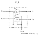
- Fig. 6 is a diagram illustrating the configuration of the selector 5.
- demodulated signals r l and r Q from the demodulator 1 are input into switching circuits 51 and 52, respectively, of the selector. Both switching circuits 51 and 52 are controlled by the output signal of the decision circuit 4.
- switching circuits 51 and 52 allow the demodulated signals provided from the demodulator 1 to be supplied as they are when the output of the decision circuit 4 is at its high level. Conversely, when the output of the decision circuit 4 is at its low level, the switching circuits 51 and 52 select the low-level signals (i.e. ground) and supply them to the UW detector 6.
- the output signal level of the low-pass filter 3 begins to drop at time t3 until it falls beyond the threshold level of the decision circuit 4 at time t4. Then, the decision circuit 4, as shown in Fig. 7(C), supplies a received signal detection-interrupt signal having a low level.
- this low-level received signal detection-interrupt signal causes the selector circuit 5 to select the fixed data (e.g ground) beginning at t4, and supply that fixed data to the unique word detecting circuit 6. As described, this fixed data is selected in a pattern unrelated to unique words, for example, all "0".
- the selector 5 at time t6 again selects the demodulated received signals as shown in Fig. 7(D). The above-described operation is then repeated.
- the selector 5 selects the fixed data instead of the received demodulated data.
- the length of period from t1 to t2 is dependent on the value of the time constant of the low-pass filter 3 and of the threshold of the decision circuit 4 in the signal detecting means 9.
- the time constant of the low-pass filter 3 and the threshold of the decision circuit 4 are selected so that the output signal level of the low-pass filter 3 reaches the threshold level before the portion of the detected demodulated signal containing the unique word has been provided to the selector 5.
- the selector will be already set by the high-level received signal detection signal, provided by the decision circuit 4, to pass the portion of the received demodulated signal containing the unique word to the UW detector 6.
- the UW detector 6 detects a unique word UW from the demodulated signals.
- a frame synchronizing circuit 7 sets the timing for receiving the frames based on a predetermined, prestored frame format corresponding to the detected UW.
- An aperture generator 8 controls the detection aperture of the UW detector 6 in accordance with the output signal of the frame synchronizing circuit 7.
- the aperture of the UW detector 6 is the time period that the UW detector remains "open" to detect the communication signal.
- the UW detector 6, frame synchronising circuit 7 and aperture generator 8 cooperate to establish frame synchronization
- the selector 5 when the decision circuit 4 indicates that actual communication signals are being received, the selector 5 supplies demodulated signals, enabling the above-described operation to maintain frame synchronization.
- the interrupt-detection signal is supplied from the decision circuit 4 to cause the selector 5 to provide fixed data to the UW detector 6.
- this fixed data has a pattern unrelated to unique words, there is no possibility that the UW detector 6 would mistakenly detect the fixed data as a unique word. Hence, erroneous detection of unique words can be prevented, and erroneous frame timing can be minimized to assure reliable satellite channel detection. Furthermore, the phase of the received signal, when determined in accordance with the unique words, is more reliably ascertained.
- the present invention is not to be restricted to the above-described preferred embodiment, but can also be used in receivers of digital satellite communication signals produced by other type or phase shift keying, such as offset QPSK (OQPSK) and 8 PSK.
- OQPSK offset QPSK
- 8 PSK 8 PSK
- the selector 5 is disposed between the unique word detector 6 and the demodulator 1 in the above-described embodiment, the present invention is not limited to this arrangement.
- FIG. 8 illustrates another embodiment of the present invention.
- Those components illustrated in Fig. 8 which are identical to those in Fig. 1 perform the same functions, and accordingly, their description is abbreviated.
- the output signals of the demodulator 1 are input into the UW detector 6.
- the output signals of the UW detector 6 are input to an inhibiting circuit 10.
- the output or the UW detector 6 is input to the frame synchronizing circuit 7.
- the output of the UW detector 6 is inhibited by the inhibiting circuit 10.
- a low level signal which is unrelated to the unique words, is input to the frame synchronizing circuit 7.
- the frame synchronizing circuit will determine that this low level signal is not a unique word and thus, will not cause the aperture generator 8 to control the aperture of the UW detector 6.
Landscapes
- Engineering & Computer Science (AREA)
- Computer Networks & Wireless Communication (AREA)
- Signal Processing (AREA)
- Synchronisation In Digital Transmission Systems (AREA)
- Digital Transmission Methods That Use Modulated Carrier Waves (AREA)
- Time-Division Multiplex Systems (AREA)
Applications Claiming Priority (3)
| Application Number | Priority Date | Filing Date | Title |
|---|---|---|---|
| JP196657/93 | 1993-06-30 | ||
| JP19665793 | 1993-06-30 | ||
| JP19665793A JPH0828754B2 (ja) | 1993-06-30 | 1993-06-30 | フレーム同期方式 |
Publications (2)
| Publication Number | Publication Date |
|---|---|
| EP0632606A1 true EP0632606A1 (de) | 1995-01-04 |
| EP0632606B1 EP0632606B1 (de) | 2001-11-14 |
Family
ID=16361430
Family Applications (1)
| Application Number | Title | Priority Date | Filing Date |
|---|---|---|---|
| EP94110233A Expired - Lifetime EP0632606B1 (de) | 1993-06-30 | 1994-06-30 | Verfahren und Gerät zur Erstellung und zum Erhalten der Rahmensynchronisation in einer Satelliten Kommunikationsanordnung |
Country Status (5)
| Country | Link |
|---|---|
| US (1) | US5619507A (de) |
| EP (1) | EP0632606B1 (de) |
| JP (1) | JPH0828754B2 (de) |
| AU (1) | AU672700B2 (de) |
| DE (1) | DE69429034T2 (de) |
Cited By (4)
| Publication number | Priority date | Publication date | Assignee | Title |
|---|---|---|---|---|
| FR2773029A1 (fr) * | 1997-12-23 | 1999-06-25 | Telecommunications Sa | Procede de synchronisation d'un recepteur sur des donnees numeriques transmises par paquets |
| EP0809377A3 (de) * | 1996-05-21 | 2002-09-11 | Nokia Corporation | Signalerfassung in eine Satellitenübertragungsanordnung |
| EP0923207A3 (de) * | 1997-12-09 | 2003-12-10 | Nec Corporation | Empfangssynchronisationsschaltung, Empfänger diesen verwendend und digitales Kommunikationssystem |
| EP1850517A4 (de) * | 2005-02-14 | 2011-01-26 | Pioneer Corp | Digital-ausstrahlungsempfänger und synchronisationsdetektionsverfahren |
Families Citing this family (93)
| Publication number | Priority date | Publication date | Assignee | Title |
|---|---|---|---|---|
| US6975582B1 (en) * | 1995-07-12 | 2005-12-13 | Ericsson Inc. | Dual mode satellite/cellular terminal |
| JP2699956B2 (ja) * | 1995-10-30 | 1998-01-19 | 日本電気株式会社 | 無線選択呼出受信機 |
| EP0779717A3 (de) * | 1995-12-13 | 2000-08-02 | Nec Corporation | Verfahren und Anordnung zur Zeitsteuerung in einer Satellitenkommunikationsanordnung |
| JP2762983B2 (ja) * | 1996-02-02 | 1998-06-11 | 日本電気株式会社 | 割り当てチャネル制御方式 |
| JP3201948B2 (ja) * | 1996-03-12 | 2001-08-27 | 三菱電機株式会社 | ディジタル無線通信受信機 |
| JPH09247115A (ja) * | 1996-03-13 | 1997-09-19 | Mitsubishi Electric Corp | ディジタル無線通信受信機 |
| US6002728A (en) * | 1997-04-17 | 1999-12-14 | Itt Manufacturing Enterprises Inc. | Synchronization and tracking in a digital communication system |
| IL120898A (en) * | 1997-05-22 | 2000-02-17 | D S P C Israel Ltd | Bi-directional channel analysis |
| JP3568182B2 (ja) * | 1997-12-03 | 2004-09-22 | 株式会社日立国際電気 | データ伝送装置の同期検出方法及びその装置 |
| JP3411214B2 (ja) * | 1998-05-22 | 2003-05-26 | 三菱電機株式会社 | ディジタル無線通信系の受信処理方法および受信機 |
| JP3850151B2 (ja) | 1998-10-20 | 2006-11-29 | 富士通株式会社 | 無線基地局受信同期保護設定方式 |
| US6336117B1 (en) | 1999-04-30 | 2002-01-01 | International Business Machines Corporation | Content-indexing search system and method providing search results consistent with content filtering and blocking policies implemented in a blocking engine |
| JP2001005675A (ja) * | 1999-06-21 | 2001-01-12 | Matsushita Electric Ind Co Ltd | プログラム変換装置及びプロセッサ |
| US6836518B1 (en) | 1999-11-16 | 2004-12-28 | Hitachi Kokusai Electric Inc. | Synchronization control method for receiver apparatus of data transmission system utilizing orthogonal frequency division multiplex, and data transmission system |
| JP4329192B2 (ja) * | 1999-11-19 | 2009-09-09 | ソニー株式会社 | 無線通信装置、無線通信システムおよびその方法 |
| US7043160B1 (en) * | 2000-08-28 | 2006-05-09 | Nortel Networks Limited | Method, system and signal for carrying overhead information in a transport network employing photonic switching nodes |
| US7046700B1 (en) * | 2001-03-08 | 2006-05-16 | Nortel Networks Limited | Spectrally invisible framing of high error rate data signals |
| JP3877579B2 (ja) * | 2001-11-26 | 2007-02-07 | 古野電気株式会社 | Tdma通信装置 |
| EP3401794A1 (de) | 2002-01-08 | 2018-11-14 | Seven Networks, LLC | Verbindungsarchitektur für ein mobiles netzwerk |
| US7203253B2 (en) * | 2002-09-26 | 2007-04-10 | Marvell World Trade Ltd. | Method and apparatus of cross-correlation |
| US8468126B2 (en) | 2005-08-01 | 2013-06-18 | Seven Networks, Inc. | Publishing data in an information community |
| US7917468B2 (en) | 2005-08-01 | 2011-03-29 | Seven Networks, Inc. | Linking of personal information management data |
| US7853563B2 (en) | 2005-08-01 | 2010-12-14 | Seven Networks, Inc. | Universal data aggregation |
| US7593488B2 (en) * | 2003-04-25 | 2009-09-22 | Harris Corporation | Method and apparatus for detection of signal without the aid of training sequence |
| CN1299446C (zh) * | 2004-05-01 | 2007-02-07 | 中兴通讯股份有限公司 | 一种时分通信系统无线接口帧同步的方法 |
| US8010082B2 (en) | 2004-10-20 | 2011-08-30 | Seven Networks, Inc. | Flexible billing architecture |
| WO2006045102A2 (en) | 2004-10-20 | 2006-04-27 | Seven Networks, Inc. | Method and apparatus for intercepting events in a communication system |
| US7706781B2 (en) | 2004-11-22 | 2010-04-27 | Seven Networks International Oy | Data security in a mobile e-mail service |
| FI117152B (fi) | 2004-12-03 | 2006-06-30 | Seven Networks Internat Oy | Sähköpostiasetusten käyttöönotto matkaviestimelle |
| US7752633B1 (en) | 2005-03-14 | 2010-07-06 | Seven Networks, Inc. | Cross-platform event engine |
| US8438633B1 (en) | 2005-04-21 | 2013-05-07 | Seven Networks, Inc. | Flexible real-time inbox access |
| US7796742B1 (en) | 2005-04-21 | 2010-09-14 | Seven Networks, Inc. | Systems and methods for simplified provisioning |
| WO2006136660A1 (en) | 2005-06-21 | 2006-12-28 | Seven Networks International Oy | Maintaining an ip connection in a mobile network |
| US8069166B2 (en) | 2005-08-01 | 2011-11-29 | Seven Networks, Inc. | Managing user-to-user contact with inferred presence information |
| KR100717878B1 (ko) * | 2005-12-09 | 2007-05-14 | 한국전자통신연구원 | 파일럿이 삽입된 위성 통신 시스템에서의 차등검출을활용한 프레임 동기 방법 |
| US7769395B2 (en) | 2006-06-20 | 2010-08-03 | Seven Networks, Inc. | Location-based operations and messaging |
| CA2767302C (en) * | 2006-09-28 | 2012-10-16 | Fujitsu Limited | Wireless communication device |
| US20080205568A1 (en) * | 2007-02-28 | 2008-08-28 | Matsushita Electric Industrial Co., Ltd. | Dsrc communication circuit and dsrc communication method |
| US8693494B2 (en) | 2007-06-01 | 2014-04-08 | Seven Networks, Inc. | Polling |
| US8805425B2 (en) | 2007-06-01 | 2014-08-12 | Seven Networks, Inc. | Integrated messaging |
| JP4424378B2 (ja) * | 2007-06-13 | 2010-03-03 | ソニー株式会社 | フレーム同期装置及びその制御方法 |
| JP5115551B2 (ja) * | 2007-11-05 | 2013-01-09 | パナソニック株式会社 | プラズマディスプレイ装置 |
| US8364181B2 (en) | 2007-12-10 | 2013-01-29 | Seven Networks, Inc. | Electronic-mail filtering for mobile devices |
| US9002828B2 (en) | 2007-12-13 | 2015-04-07 | Seven Networks, Inc. | Predictive content delivery |
| US8793305B2 (en) * | 2007-12-13 | 2014-07-29 | Seven Networks, Inc. | Content delivery to a mobile device from a content service |
| US8107921B2 (en) | 2008-01-11 | 2012-01-31 | Seven Networks, Inc. | Mobile virtual network operator |
| US8862657B2 (en) | 2008-01-25 | 2014-10-14 | Seven Networks, Inc. | Policy based content service |
| US20090193338A1 (en) | 2008-01-28 | 2009-07-30 | Trevor Fiatal | Reducing network and battery consumption during content delivery and playback |
| US8787947B2 (en) | 2008-06-18 | 2014-07-22 | Seven Networks, Inc. | Application discovery on mobile devices |
| US8078158B2 (en) | 2008-06-26 | 2011-12-13 | Seven Networks, Inc. | Provisioning applications for a mobile device |
| US8909759B2 (en) | 2008-10-10 | 2014-12-09 | Seven Networks, Inc. | Bandwidth measurement |
| EP2280510B1 (de) * | 2009-07-09 | 2016-05-04 | STMicroelectronics S.r.l. | Verfahren zum Bestimmen eines Rahmensynchronisierungsmusters oder eines Einzelwortes in einem empfangenen digitalen Signal |
| WO2011126889A2 (en) | 2010-03-30 | 2011-10-13 | Seven Networks, Inc. | 3d mobile user interface with configurable workspace management |
| GB2500333B (en) | 2010-07-26 | 2014-10-08 | Seven Networks Inc | Mobile application traffic optimization |
| US8838783B2 (en) | 2010-07-26 | 2014-09-16 | Seven Networks, Inc. | Distributed caching for resource and mobile network traffic management |
| WO2012018430A1 (en) | 2010-07-26 | 2012-02-09 | Seven Networks, Inc. | Mobile network traffic coordination across multiple applications |
| EP2599345B1 (de) | 2010-07-26 | 2017-09-06 | Seven Networks, LLC | Verteilte implementierung dynamischer drahtlosverkehrsrichtlinien |
| GB2499534B (en) | 2010-11-01 | 2018-09-19 | Seven Networks Llc | Caching adapted for mobile application behavior and network conditions |
| US9330196B2 (en) | 2010-11-01 | 2016-05-03 | Seven Networks, Llc | Wireless traffic management system cache optimization using http headers |
| US8326985B2 (en) | 2010-11-01 | 2012-12-04 | Seven Networks, Inc. | Distributed management of keep-alive message signaling for mobile network resource conservation and optimization |
| US8843153B2 (en) | 2010-11-01 | 2014-09-23 | Seven Networks, Inc. | Mobile traffic categorization and policy for network use optimization while preserving user experience |
| US9060032B2 (en) | 2010-11-01 | 2015-06-16 | Seven Networks, Inc. | Selective data compression by a distributed traffic management system to reduce mobile data traffic and signaling traffic |
| US8484314B2 (en) | 2010-11-01 | 2013-07-09 | Seven Networks, Inc. | Distributed caching in a wireless network of content delivered for a mobile application over a long-held request |
| WO2012060995A2 (en) | 2010-11-01 | 2012-05-10 | Michael Luna | Distributed caching in a wireless network of content delivered for a mobile application over a long-held request |
| US8204953B2 (en) | 2010-11-01 | 2012-06-19 | Seven Networks, Inc. | Distributed system for cache defeat detection and caching of content addressed by identifiers intended to defeat cache |
| US8166164B1 (en) | 2010-11-01 | 2012-04-24 | Seven Networks, Inc. | Application and network-based long poll request detection and cacheability assessment therefor |
| EP2636268B1 (de) | 2010-11-22 | 2019-02-27 | Seven Networks, LLC | Optimierung von ressourcenabfrageintervallen zur zufriedenstellenden beantwortung von anfragen auf mobilen vorrichtungen |
| GB2495463B (en) | 2010-11-22 | 2013-10-09 | Seven Networks Inc | Aligning data transfer to optimize connections established for transmission over a wireless network |
| EP2661697B1 (de) | 2011-01-07 | 2018-11-21 | Seven Networks, LLC | System und verfahren zur reduzierung eines mobilnetzwerkverkehrs für domänennamensystem (dns)-anfragen |
| GB2504411A (en) | 2011-04-19 | 2014-01-29 | Seven Networks Inc | Shared resource and virtual resource management in a networked environment |
| WO2012149221A2 (en) | 2011-04-27 | 2012-11-01 | Seven Networks, Inc. | System and method for making requests on behalf of a mobile device based on atomic processes for mobile network traffic relief |
| US8621075B2 (en) | 2011-04-27 | 2013-12-31 | Seven Metworks, Inc. | Detecting and preserving state for satisfying application requests in a distributed proxy and cache system |
| EP2737741A4 (de) | 2011-07-27 | 2015-01-21 | Seven Networks Inc | Überwachung der aktivitäten von mobilanwendungen für böswilligem verkehr auf einer mobiler vorrichtung |
| US8918503B2 (en) | 2011-12-06 | 2014-12-23 | Seven Networks, Inc. | Optimization of mobile traffic directed to private networks and operator configurability thereof |
| US8977755B2 (en) | 2011-12-06 | 2015-03-10 | Seven Networks, Inc. | Mobile device and method to utilize the failover mechanism for fault tolerance provided for mobile traffic management and network/device resource conservation |
| US9277443B2 (en) | 2011-12-07 | 2016-03-01 | Seven Networks, Llc | Radio-awareness of mobile device for sending server-side control signals using a wireless network optimized transport protocol |
| EP2788889A4 (de) | 2011-12-07 | 2015-08-12 | Seven Networks Inc | Flexible und dynamische integrationsschemata eines verkehrsverwaltungssystems mit verschiedenen netzwerkbetreibern zur netzwerkverkehrabschwächung |
| EP2792188B1 (de) | 2011-12-14 | 2019-03-20 | Seven Networks, LLC | Mobilfunknetzbenachrichtigung und nutzungsanalysesystem sowie verfahren mittels aggregation von daten in einem verteilten verkehrsoptimierungssystem |
| WO2013090834A1 (en) | 2011-12-14 | 2013-06-20 | Seven Networks, Inc. | Operation modes for mobile traffic optimization and concurrent management of optimized and non-optimized traffic |
| WO2013090821A1 (en) | 2011-12-14 | 2013-06-20 | Seven Networks, Inc. | Hierarchies and categories for management and deployment of policies for distributed wireless traffic optimization |
| EP2801236A4 (de) | 2012-01-05 | 2015-10-21 | Seven Networks Inc | Detektion und verwaltung von benutzerinteraktionen mit vordergrundanwendungen auf einer mobilvorrichtung in verteilten cache-speichern |
| WO2013116856A1 (en) | 2012-02-02 | 2013-08-08 | Seven Networks, Inc. | Dynamic categorization of applications for network access in a mobile network |
| US9326189B2 (en) | 2012-02-03 | 2016-04-26 | Seven Networks, Llc | User as an end point for profiling and optimizing the delivery of content and data in a wireless network |
| US8812695B2 (en) | 2012-04-09 | 2014-08-19 | Seven Networks, Inc. | Method and system for management of a virtual network connection without heartbeat messages |
| WO2013155208A1 (en) | 2012-04-10 | 2013-10-17 | Seven Networks, Inc. | Intelligent customer service/call center services enhanced using real-time and historical mobile application and traffic-related statistics collected by a distributed caching system in a mobile network |
| US8775631B2 (en) | 2012-07-13 | 2014-07-08 | Seven Networks, Inc. | Dynamic bandwidth adjustment for browsing or streaming activity in a wireless network based on prediction of user behavior when interacting with mobile applications |
| US9161258B2 (en) | 2012-10-24 | 2015-10-13 | Seven Networks, Llc | Optimized and selective management of policy deployment to mobile clients in a congested network to prevent further aggravation of network congestion |
| US9307493B2 (en) | 2012-12-20 | 2016-04-05 | Seven Networks, Llc | Systems and methods for application management of mobile device radio state promotion and demotion |
| US9271238B2 (en) | 2013-01-23 | 2016-02-23 | Seven Networks, Llc | Application or context aware fast dormancy |
| US8874761B2 (en) | 2013-01-25 | 2014-10-28 | Seven Networks, Inc. | Signaling optimization in a wireless network for traffic utilizing proprietary and non-proprietary protocols |
| US8750123B1 (en) | 2013-03-11 | 2014-06-10 | Seven Networks, Inc. | Mobile device equipped with mobile network congestion recognition to make intelligent decisions regarding connecting to an operator network |
| US9065765B2 (en) | 2013-07-22 | 2015-06-23 | Seven Networks, Inc. | Proxy server associated with a mobile carrier for enhancing mobile traffic management in a mobile network |
| JP6271411B2 (ja) * | 2014-12-25 | 2018-01-31 | 大井電気株式会社 | プリアンブル検出装置 |
Citations (4)
| Publication number | Priority date | Publication date | Assignee | Title |
|---|---|---|---|---|
| EP0371500A2 (de) | 1988-12-01 | 1990-06-06 | Nec Corporation | TDMA-Satellitennachrichtensystem mit breiten oder schmalen Zeitfensterbetriebsarten zum Empfang von Bursts mit unterschliedlichen Zeitabweichungen |
| EP0445522A2 (de) * | 1990-02-13 | 1991-09-11 | Pioneer Electronic Corporation | Verfahren zur Erfassung von Satellitensendungen für einen GPS-Empfänger |
| GB2253971A (en) * | 1984-10-30 | 1992-09-23 | Secr Defence | Ionospheric sounding system |
| EP0504905A2 (de) * | 1991-03-20 | 1992-09-23 | Nec Corporation | Trägerrückgewinnungsregelung mit sequenzieller Synchronisationserkennung durch Vorwärts-Fehlerkorrektur, und mit Rahmensynchronisationserkennung |
Family Cites Families (7)
| Publication number | Priority date | Publication date | Assignee | Title |
|---|---|---|---|---|
| JPS6122481A (ja) * | 1984-07-09 | 1986-01-31 | Victor Co Of Japan Ltd | 磁気記録再生方式 |
| JPS62180634A (ja) * | 1986-02-04 | 1987-08-07 | Toshiba Corp | フレ−ム同期方式 |
| JPS62214739A (ja) * | 1986-03-15 | 1987-09-21 | Nec Corp | 同期制御方式 |
| JP2595602B2 (ja) * | 1988-01-11 | 1997-04-02 | 日本電気株式会社 | 衛星通信地球局送受信方式 |
| JPH0716206B2 (ja) * | 1988-08-05 | 1995-02-22 | 日本電気株式会社 | 信号検出器 |
| JP2638273B2 (ja) * | 1989-09-26 | 1997-08-06 | 日本電気株式会社 | ユニーク・ワード検出方式 |
| JP2623375B2 (ja) * | 1991-03-07 | 1997-06-25 | 松下電器産業株式会社 | データ受信装置 |
-
1993
- 1993-06-30 JP JP19665793A patent/JPH0828754B2/ja not_active Expired - Fee Related
-
1994
- 1994-06-30 US US08/268,454 patent/US5619507A/en not_active Expired - Lifetime
- 1994-06-30 DE DE69429034T patent/DE69429034T2/de not_active Expired - Fee Related
- 1994-06-30 AU AU66086/94A patent/AU672700B2/en not_active Ceased
- 1994-06-30 EP EP94110233A patent/EP0632606B1/de not_active Expired - Lifetime
Patent Citations (4)
| Publication number | Priority date | Publication date | Assignee | Title |
|---|---|---|---|---|
| GB2253971A (en) * | 1984-10-30 | 1992-09-23 | Secr Defence | Ionospheric sounding system |
| EP0371500A2 (de) | 1988-12-01 | 1990-06-06 | Nec Corporation | TDMA-Satellitennachrichtensystem mit breiten oder schmalen Zeitfensterbetriebsarten zum Empfang von Bursts mit unterschliedlichen Zeitabweichungen |
| EP0445522A2 (de) * | 1990-02-13 | 1991-09-11 | Pioneer Electronic Corporation | Verfahren zur Erfassung von Satellitensendungen für einen GPS-Empfänger |
| EP0504905A2 (de) * | 1991-03-20 | 1992-09-23 | Nec Corporation | Trägerrückgewinnungsregelung mit sequenzieller Synchronisationserkennung durch Vorwärts-Fehlerkorrektur, und mit Rahmensynchronisationserkennung |
Non-Patent Citations (2)
| Title |
|---|
| HEIICHI YAMAMOTO ET AL.: "Information and Communication Engineers", 1989, INSTITUTE OF ELECTRONICS |
| W.W. WU: "Elements of Digital Satellite Communication", vol. 1, 1984, COMPUTER SCIENCE PRESS |
Cited By (5)
| Publication number | Priority date | Publication date | Assignee | Title |
|---|---|---|---|---|
| EP0809377A3 (de) * | 1996-05-21 | 2002-09-11 | Nokia Corporation | Signalerfassung in eine Satellitenübertragungsanordnung |
| EP0923207A3 (de) * | 1997-12-09 | 2003-12-10 | Nec Corporation | Empfangssynchronisationsschaltung, Empfänger diesen verwendend und digitales Kommunikationssystem |
| FR2773029A1 (fr) * | 1997-12-23 | 1999-06-25 | Telecommunications Sa | Procede de synchronisation d'un recepteur sur des donnees numeriques transmises par paquets |
| EP0926858A1 (de) * | 1997-12-23 | 1999-06-30 | Sagem Sa | Verfahren zur Synchronisierung eines Empfängers auf digitalen Paketdatensignalen |
| EP1850517A4 (de) * | 2005-02-14 | 2011-01-26 | Pioneer Corp | Digital-ausstrahlungsempfänger und synchronisationsdetektionsverfahren |
Also Published As
| Publication number | Publication date |
|---|---|
| EP0632606B1 (de) | 2001-11-14 |
| DE69429034T2 (de) | 2002-08-29 |
| US5619507A (en) | 1997-04-08 |
| JPH0795252A (ja) | 1995-04-07 |
| AU672700B2 (en) | 1996-10-10 |
| DE69429034D1 (de) | 2001-12-20 |
| JPH0828754B2 (ja) | 1996-03-21 |
| AU6608694A (en) | 1995-01-12 |
Similar Documents
| Publication | Publication Date | Title |
|---|---|---|
| EP0632606B1 (de) | Verfahren und Gerät zur Erstellung und zum Erhalten der Rahmensynchronisation in einer Satelliten Kommunikationsanordnung | |
| EP0746931B1 (de) | Digitaler demodulator mit frequenzsteuerung und zeitlicher regulierung | |
| US4599732A (en) | Technique for acquiring timing and frequency synchronization for modem utilizing known (non-data) symbols as part of their normal transmitted data format | |
| EP0355587B1 (de) | Takt- und Trägerrückgewinnung für TDMA ohne Präambelfolge | |
| EP0318685B1 (de) | TDMA-kohärenter Phasenquadraturenempfänger für Mehrwegkanäle mit Fading | |
| US4847869A (en) | Rapid reference acquisition and phase error compensation for radio transmission of data | |
| US5881098A (en) | Efficient demodulation scheme for DSSS communication | |
| US5553098A (en) | Demodulator with selectable coherent and differential data | |
| US5075697A (en) | Dual polarization transmission system | |
| CA2025232C (en) | Carrier recovery system | |
| US5497400A (en) | Decision feedback demodulator with phase and frequency estimation | |
| EP0593015B1 (de) | Trägerphasenverriegelungsdetektor für PSK-Satellitensysteme | |
| HK1002134A1 (en) | Digital demodulator for pi/4 - qpsk signals | |
| HK1002134B (en) | Digital demodulator for pi/4 - qpsk signals | |
| US5073906A (en) | Synchronization word detection apparatus | |
| US20030016079A1 (en) | Doppler learning phase lock loop for burst demodulator | |
| JP2590441B2 (ja) | 干渉波検出方法 | |
| EP0720325B1 (de) | System zur Gewinnung eines gewünschten Trägers aus einem FDM-Signal | |
| JPS5845870B2 (ja) | フレ−ム同期引込方式 | |
| JPH05199270A (ja) | ディジタルマイクロ波無線装置 |
Legal Events
| Date | Code | Title | Description |
|---|---|---|---|
| PUAI | Public reference made under article 153(3) epc to a published international application that has entered the european phase |
Free format text: ORIGINAL CODE: 0009012 |
|
| 17P | Request for examination filed |
Effective date: 19941019 |
|
| AK | Designated contracting states |
Kind code of ref document: A1 Designated state(s): DE FR GB |
|
| 17Q | First examination report despatched |
Effective date: 19980421 |
|
| GRAG | Despatch of communication of intention to grant |
Free format text: ORIGINAL CODE: EPIDOS AGRA |
|
| RTI1 | Title (correction) |
Free format text: METHOD AND APPARATUS FOR ESTABLISHING AND MAINTAINING FRAME SYNCHRONIZATION IN A SATELLITE COMMUNICATION SYSTEM |
|
| GRAG | Despatch of communication of intention to grant |
Free format text: ORIGINAL CODE: EPIDOS AGRA |
|
| GRAH | Despatch of communication of intention to grant a patent |
Free format text: ORIGINAL CODE: EPIDOS IGRA |
|
| GRAH | Despatch of communication of intention to grant a patent |
Free format text: ORIGINAL CODE: EPIDOS IGRA |
|
| GRAA | (expected) grant |
Free format text: ORIGINAL CODE: 0009210 |
|
| AK | Designated contracting states |
Kind code of ref document: B1 Designated state(s): DE FR GB |
|
| REF | Corresponds to: |
Ref document number: 69429034 Country of ref document: DE Date of ref document: 20011220 |
|
| REG | Reference to a national code |
Ref country code: GB Ref legal event code: IF02 |
|
| ET | Fr: translation filed | ||
| PLBE | No opposition filed within time limit |
Free format text: ORIGINAL CODE: 0009261 |
|
| STAA | Information on the status of an ep patent application or granted ep patent |
Free format text: STATUS: NO OPPOSITION FILED WITHIN TIME LIMIT |
|
| 26N | No opposition filed | ||
| PGFP | Annual fee paid to national office [announced via postgrant information from national office to epo] |
Ref country code: GB Payment date: 20090624 Year of fee payment: 16 Ref country code: DE Payment date: 20090626 Year of fee payment: 16 |
|
| GBPC | Gb: european patent ceased through non-payment of renewal fee |
Effective date: 20100630 |
|
| REG | Reference to a national code |
Ref country code: FR Ref legal event code: ST Effective date: 20110228 |
|
| PG25 | Lapsed in a contracting state [announced via postgrant information from national office to epo] |
Ref country code: DE Free format text: LAPSE BECAUSE OF NON-PAYMENT OF DUE FEES Effective date: 20110101 |
|
| PG25 | Lapsed in a contracting state [announced via postgrant information from national office to epo] |
Ref country code: FR Free format text: LAPSE BECAUSE OF NON-PAYMENT OF DUE FEES Effective date: 20100630 |
|
| PG25 | Lapsed in a contracting state [announced via postgrant information from national office to epo] |
Ref country code: GB Free format text: LAPSE BECAUSE OF NON-PAYMENT OF DUE FEES Effective date: 20100630 |
|
| PGFP | Annual fee paid to national office [announced via postgrant information from national office to epo] |
Ref country code: FR Payment date: 20090611 Year of fee payment: 16 |