EP0632609A2 - Procédé et appareil pour la prévention d'interférence électromagnétique - Google Patents
Procédé et appareil pour la prévention d'interférence électromagnétique Download PDFInfo
- Publication number
- EP0632609A2 EP0632609A2 EP94304527A EP94304527A EP0632609A2 EP 0632609 A2 EP0632609 A2 EP 0632609A2 EP 94304527 A EP94304527 A EP 94304527A EP 94304527 A EP94304527 A EP 94304527A EP 0632609 A2 EP0632609 A2 EP 0632609A2
- Authority
- EP
- European Patent Office
- Prior art keywords
- signal
- radio
- power
- average
- idle mode
- Prior art date
- Legal status (The legal status is an assumption and is not a legal conclusion. Google has not performed a legal analysis and makes no representation as to the accuracy of the status listed.)
- Withdrawn
Links
Images


Classifications
-
- H—ELECTRICITY
- H04—ELECTRIC COMMUNICATION TECHNIQUE
- H04B—TRANSMISSION
- H04B15/00—Suppression or limitation of noise or interference
-
- H—ELECTRICITY
- H04—ELECTRIC COMMUNICATION TECHNIQUE
- H04B—TRANSMISSION
- H04B7/00—Radio transmission systems, i.e. using radiation field
- H04B7/14—Relay systems
- H04B7/15—Active relay systems
- H04B7/204—Multiple access
- H04B7/212—Time-division multiple access [TDMA]
Definitions
- the present invention relates to radio in general, and more particularly, to methods and apparatus which prevent RF baseband interference.
- Any RF signal with a time-varying envelope can induce baseband interference in a device characterized by a nonlinear response to radio waves.
- the mechanism could be, but is not necessarily, a second-order nonlinearity that produces an effect similar to that of a square-law envelope detector.
- the square-law-detected envelope contains significant energy in the audio band, the result could be, for example, undesirable interference to wearers of hearing aids.
- the present invention provides a technique for diminishing the interference caused by an RF signal with a time-varying envelope while avoiding many of the costs and restrictions associated with other techniques.
- embodiments of the present invention can be especially well-suited for radios in systems employing time division multiple access (“TDMA”) (e.g., GSM, IS-54, JDC), time division duplexing (“TDD”) (e.g., CT-2), and hybrid systems (“TDMA/TDD”) (e.g., PHP and DECT).
- TDMA time division multiple access
- TDD time division duplexing
- TDMA/TDD hybrid systems
- TDMA, TDD and TDMA/TDD systems shall all be referred to as TDMA systems.
- TDMA radio having a transmit mode and an idle mode.
- the radio transmits an information-bearing signal in a first frequency channel with a first average RF power.
- the radio transmits a signal in a second frequency channel with a second average RF power.
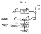
- FIG. 1 shows a block diagram of an illustrative embodiment of the present invention.
- FIG. 2 depicts a block diagram of a second illustrative embodiment of the present invention.
- FIG. 3 depicts a flowchart of the operation of an illustrative embodiment of the present invention.
- FIG. 1 depicts a block diagram of an illustrative embodiment of the present invention as presented in the context of a time division multiple access (“TDMA”) communications system, a time division duplex (“TDD”) system, or a hybrid TDMA/TDD system.
- TDMA time division multiple access
- TDD time division duplex
- FIG. 1 depicts a block diagram of an illustrative embodiment of the present invention as presented in the context of a time division multiple access (“TDMA”) communications system, a time division duplex (“TDD”) system, or a hybrid TDMA/TDD system.
- TDMA time division multiple access
- TDD time division duplex
- hybrid TDMA/TDD system a hybrid TDMA/TDD system.
- TMDA time division multiple access
- TMDA time division multiple access
- TMDA time division duplex
- Each user's radio has (1) a transmit mode, when an information-bearing signal is radiated in the shared frequency channel, and (2) an idle mode, when nothing is
- each radio When one user's radio is in transmit mode, the other users' radios are in idle mode, so as to prevent a cacophony in the shared frequency channel. The respective users take turns transmitting and being idle, so that others may transmit.
- the rate at which a single radio cycles between transmit mode and idle mode is referred to as the "frame rate."
- each radio ceases radiating while it is in idle mode (1) so as to not interfere with the appropriately radiating radio, and (2) so as to conserve power.
- the repetitive radiating and not-radiating of a radio in accordance with the frame rate causes a time-varying RF envelope which can cause undesirable RF interference.
- the frame rate corresponds to an audio-band frequency
- the result can be interference to wearers of hearing aids.
- the time-varying RF envelope interference could be diminished if each radio transmitted during its idle mode as well as during its transmit mode, and with the same average RF power. This, however, as mentioned above, would cause each user to interfere with the other users.
- the illustrative embodiment of the present invention shown in FIG. 1 overcomes this problem by radiating normally during transmit mode, and by also radiating during idle at substantially the same average RF power as during transmit mode, but in a different frequency channel.
- the idle mode frequency channel is advantageously close to the transmit mode frequency channel but is specifically designated for these transmissions. By closely matching the average RF power levels radiated during both the transmit and idle modes the time-varying RF envelope interference can be greatly diminished.
- an information-bearing signal (e.g., voice, data, etc.) is advantageously fed into amplifier 101.
- the gain of amplifier 101 is advantageously controlled by automatic gain control 113.
- the signal passes to modulator 103 where it is modulated onto a signal received from programmable synthesizer 115.
- the modulated signal is fed into amplifier 105 and to antenna 109.
- Tap 107 samples the signal fed to antenna 109 and feeds the samples to envelope detector 111.
- Envelope detector 111 feeds a signal to automatic gain control 113 representative of the average RF power of the radiated signal.
- tap 107 and envelope detector 111 It will be clear to those skilled in the art how to make and use tap 107 and envelope detector 111. It should be remembered that the purpose of amplifier 101, tap 107, envelope detector 111 and automatic gain control 113 is to assure that the illustrative embodiment always radiates at substantially close to the same average RF power whether the embodiment is in transmit mode or idle mode.
- Controller 119 receives a signal indicating whether the embodiment is in transmit mode or idle mode. When the embodiment is in transmit mode, controller 119 directs programmable synthesizer 115 to synthesize a carrier in the frequency channel assigned to the embodiment for normal transmission. When, however, the embodiment is in idle mode, controller 119 directs programmable synthesizer 115 to synthesize a carrier in a frequency channel set aside for spurious transmissions. Oscillator 117 provides a reference signal to programmable synthesizer 115. It will be clear to those skilled in the art how to make and use controller 119 and oscillator 117.
- an information-bearing signal (e.g., voice, data, etc.) is advantageously fed into amplifier 201.
- the gain of amplifier 201 is advantageously controlled by automatic gain control 213. From amplifier 201, the signal passes to modulator 203 where it is modulated onto a signal received from switch 221. It will be clear to those skilled in the art how to make and use amplifier 201, automatic gain control 213, modulator 203 and switch 221.
- the modulated signal is fed into amplifier 205, through tap 207 and to antenna 209. Tap 207 samples the signal fed to antenna 209 and feeds the samples to envelope detector 211. Envelope detector 211 feeds a signal to automatic gain control 213 representative of the average RF power of the radiated signal.
- tap 207 and envelope detector 211 It will be clear to those skilled in the art how to make and use tap 207 and envelope detector 211. It should be remembered that the purpose of amplifier 201, tap 207, envelope detector 211 and automatic gain control 213 is to assure that the illustrative embodiment always radiates at substantially close to the same average RF power whether the embodiment is in transmit mode or idle mode.
- Switch 221 receives a signal indicating whether the embodiment is in transmit mode or idle mode, the synthesized carrier in the frequency channel assigned to the embodiment for normal transmission (from synthesizer 215), and a carrier in a frequency channel set aside for spurious transmissions.
- switch 221 directs the carrier from programmable synthesizer 215 to modulator 203, but when, however, the embodiment is in idle mode, switch 221 directs the carrier from oscillator 223 to modulator 203.
- the illustrative embodiment in FIG. 2 is advantageous in that synthesizer 215 need not be programmable and oscillator 223 can be relatively less precise than oscillator 217, which provides a reference signal to programmable synthesizer 215. It will be clear to those skilled in the art how to make and use this embodiment of the present invention.
- FIG. 1 and FIG. 2 The operation of the illustrative embodiments in FIG. 1 and FIG. 2 can be depicted by the flowchart in FIG. 3.
Landscapes
- Engineering & Computer Science (AREA)
- Computer Networks & Wireless Communication (AREA)
- Signal Processing (AREA)
- Transmitters (AREA)
- Mobile Radio Communication Systems (AREA)
- Time-Division Multiplex Systems (AREA)
Applications Claiming Priority (2)
| Application Number | Priority Date | Filing Date | Title |
|---|---|---|---|
| US8560393A | 1993-06-30 | 1993-06-30 | |
| US85603 | 1993-06-30 |
Publications (2)
| Publication Number | Publication Date |
|---|---|
| EP0632609A2 true EP0632609A2 (fr) | 1995-01-04 |
| EP0632609A3 EP0632609A3 (fr) | 1995-12-27 |
Family
ID=22192729
Family Applications (1)
| Application Number | Title | Priority Date | Filing Date |
|---|---|---|---|
| EP94304527A Withdrawn EP0632609A3 (fr) | 1993-06-30 | 1994-06-22 | Procédé et appareil pour la prévention d'interférence électromagnétique. |
Country Status (4)
| Country | Link |
|---|---|
| EP (1) | EP0632609A3 (fr) |
| JP (1) | JPH07154353A (fr) |
| KR (1) | KR950002269A (fr) |
| CN (1) | CN1103220A (fr) |
Cited By (9)
| Publication number | Priority date | Publication date | Assignee | Title |
|---|---|---|---|---|
| WO1997027712A1 (fr) * | 1996-01-24 | 1997-07-31 | Ericsson Inc. | Telephone sans fil a duplexage temporel a mode compatible avec un appareil de correction auditive |
| WO1997039537A1 (fr) * | 1996-04-16 | 1997-10-23 | Qualcomm Incorporated | Systeme et procede pour reduire les interferences generees par un appareil de communication numerique |
| WO1997041653A1 (fr) * | 1996-04-29 | 1997-11-06 | Qualcomm Incorporated | Systeme et procede de reduction des interferences a modulation d'amplitude generees par un dispositif de communications a acces multiple par difference de code |
| EP0765043A3 (fr) * | 1995-09-19 | 2000-01-19 | AT&T Corp. | Radio émetteur/récepteur à multiplexage temporel et à haut rendement avec une interférence de bande de base |
| EP0765042A3 (fr) * | 1995-09-19 | 2000-01-19 | AT&T Corp. | Radioémetteur/-récepteur à multiplexage temporel avec une interférence de bande de base reduite |
| KR100509903B1 (ko) * | 1996-04-16 | 2005-11-08 | 콸콤 인코포레이티드 | 디지털통신장치에의해발생된방해를감소시키는시스템및방법 |
| US7929723B2 (en) | 1997-01-13 | 2011-04-19 | Micro Ear Technology, Inc. | Portable system for programming hearing aids |
| US8300862B2 (en) | 2006-09-18 | 2012-10-30 | Starkey Kaboratories, Inc | Wireless interface for programming hearing assistance devices |
| US9344817B2 (en) | 2000-01-20 | 2016-05-17 | Starkey Laboratories, Inc. | Hearing aid systems |
Families Citing this family (3)
| Publication number | Priority date | Publication date | Assignee | Title |
|---|---|---|---|---|
| US6449662B1 (en) | 1997-01-13 | 2002-09-10 | Micro Ear Technology, Inc. | System for programming hearing aids |
| US6424722B1 (en) | 1997-01-13 | 2002-07-23 | Micro Ear Technology, Inc. | Portable system for programming hearing aids |
| US7082113B1 (en) * | 1998-09-18 | 2006-07-25 | Lucent Technologies, Inc. | TDMA communication system and method including discontinuous modulation for reducing adjacent and co-channel interference |
Family Cites Families (2)
| Publication number | Priority date | Publication date | Assignee | Title |
|---|---|---|---|---|
| GB2238449B (en) * | 1989-11-10 | 1993-11-24 | Trade And Industry Secretary O | Improvements in or relating to TDMA systems |
| JP2800500B2 (ja) * | 1991-10-01 | 1998-09-21 | 松下電器産業株式会社 | バースト送信出力制御回路 |
-
1994
- 1994-06-22 EP EP94304527A patent/EP0632609A3/fr not_active Withdrawn
- 1994-06-28 CN CN94107959A patent/CN1103220A/zh active Pending
- 1994-06-29 JP JP6168606A patent/JPH07154353A/ja active Pending
- 1994-06-29 KR KR1019940015124A patent/KR950002269A/ko not_active Withdrawn
Cited By (15)
| Publication number | Priority date | Publication date | Assignee | Title |
|---|---|---|---|---|
| EP0765043A3 (fr) * | 1995-09-19 | 2000-01-19 | AT&T Corp. | Radio émetteur/récepteur à multiplexage temporel et à haut rendement avec une interférence de bande de base |
| EP0765042A3 (fr) * | 1995-09-19 | 2000-01-19 | AT&T Corp. | Radioémetteur/-récepteur à multiplexage temporel avec une interférence de bande de base reduite |
| US6122500A (en) * | 1996-01-24 | 2000-09-19 | Ericsson, Inc. | Cordless time-duplex phone with improved hearing-aid compatible mode |
| WO1997027712A1 (fr) * | 1996-01-24 | 1997-07-31 | Ericsson Inc. | Telephone sans fil a duplexage temporel a mode compatible avec un appareil de correction auditive |
| AU715244B2 (en) * | 1996-04-16 | 2000-01-20 | Qualcomm Incorporated | System and method for reducing interference generated by a digital communication device |
| US5917812A (en) * | 1996-04-16 | 1999-06-29 | Qualcomm Incorporated | System and method for reducing interference generated by a digital communication device |
| WO1997039537A1 (fr) * | 1996-04-16 | 1997-10-23 | Qualcomm Incorporated | Systeme et procede pour reduire les interferences generees par un appareil de communication numerique |
| KR100509903B1 (ko) * | 1996-04-16 | 2005-11-08 | 콸콤 인코포레이티드 | 디지털통신장치에의해발생된방해를감소시키는시스템및방법 |
| WO1997041653A1 (fr) * | 1996-04-29 | 1997-11-06 | Qualcomm Incorporated | Systeme et procede de reduction des interferences a modulation d'amplitude generees par un dispositif de communications a acces multiple par difference de code |
| US6714597B1 (en) | 1996-04-29 | 2004-03-30 | Qualcomm Incorporated | System and method for reducing interference generated by a CDMA communications device |
| KR100493484B1 (ko) * | 1996-04-29 | 2005-07-25 | 콸콤 인코포레이티드 | Cdma통신장치에의해발생된am-간섭을감소시키기위한시스템및방법 |
| US7929723B2 (en) | 1997-01-13 | 2011-04-19 | Micro Ear Technology, Inc. | Portable system for programming hearing aids |
| US9344817B2 (en) | 2000-01-20 | 2016-05-17 | Starkey Laboratories, Inc. | Hearing aid systems |
| US9357317B2 (en) | 2000-01-20 | 2016-05-31 | Starkey Laboratories, Inc. | Hearing aid systems |
| US8300862B2 (en) | 2006-09-18 | 2012-10-30 | Starkey Kaboratories, Inc | Wireless interface for programming hearing assistance devices |
Also Published As
| Publication number | Publication date |
|---|---|
| EP0632609A3 (fr) | 1995-12-27 |
| CN1103220A (zh) | 1995-05-31 |
| JPH07154353A (ja) | 1995-06-16 |
| KR950002269A (ko) | 1995-01-04 |
Similar Documents
| Publication | Publication Date | Title |
|---|---|---|
| EP0765043B1 (fr) | Radio émetteur/récepteur à multiplexage temporel et à haut rendement avec une interférence de bande de base | |
| US6031831A (en) | Method for reverse channel sounding in a communications system | |
| US5220678A (en) | Method and apparatus for adjusting the power of a transmitter | |
| EP0692162B1 (fr) | Procede et appareil fournissant une indication de la qualite d'une liaison de communication | |
| JP4486884B2 (ja) | 選択的な電力制御メッセージング | |
| EP0632609A2 (fr) | Procédé et appareil pour la prévention d'interférence électromagnétique | |
| US6603825B1 (en) | Automatic gain control for a receiver and method therefor | |
| US7069041B2 (en) | Radio terminal apparatus and its reception control program | |
| US20170250764A1 (en) | Transmission control method and apparatus | |
| EP0765042A2 (fr) | Radioémetteur/-récepteur à multiplexage temporel avec une interférence de bande de base reduite | |
| KR20080016876A (ko) | 통신 시스템에서 스퓨리어스 전송을 제어하는 방법 및 장치 | |
| US6735451B1 (en) | Method and apparatus for providing downlink power control in radio communication systems employing virtual cells | |
| US6701157B2 (en) | Transmitter circuit architecture and method for reducing in-band noise in point to multipoint communication systems | |
| JPH02192231A (ja) | 送信電力制御方式 | |
| WO2002019567A1 (fr) | Station radio de base, procede de commande de directivite destine a une station radio de base, et programme | |
| JPS6230426A (ja) | 無線通信装置 | |
| US20110205940A1 (en) | Wireless communication device, wireless communication system, and wireless communication method | |
| JPH07321547A (ja) | 無線伝送装置 | |
| KR20010050670A (ko) | 수신기의 다이나믹 랜지 경감을 위해 파워에 근거한 동적채널 할당을 위한 방법 및 장치 | |
| GB2376606A (en) | A method of reducing interference to communications in Time Division Duplexing (TDD) Mode between a TDD mobile and a TDD base station | |
| JPH05122125A (ja) | 送信電力制御方式 | |
| JP2000209165A (ja) | 送受信試験方法および装置 | |
| JP2972717B1 (ja) | 無線基地局及びそれを用いた移動通信システム | |
| JPH0226132A (ja) | 移動無線通信装置 | |
| JPS63227222A (ja) | 送信電力制御方式 |
Legal Events
| Date | Code | Title | Description |
|---|---|---|---|
| PUAI | Public reference made under article 153(3) epc to a published international application that has entered the european phase |
Free format text: ORIGINAL CODE: 0009012 |
|
| AK | Designated contracting states |
Kind code of ref document: A2 Designated state(s): DE FR GB IT |
|
| PUAL | Search report despatched |
Free format text: ORIGINAL CODE: 0009013 |
|
| AK | Designated contracting states |
Kind code of ref document: A3 Designated state(s): DE FR GB IT |
|
| 17P | Request for examination filed |
Effective date: 19960613 |
|
| STAA | Information on the status of an ep patent application or granted ep patent |
Free format text: STATUS: THE APPLICATION HAS BEEN WITHDRAWN |
|
| 18W | Application withdrawn |
Withdrawal date: 19990827 |