EP0632914B1 - Verfahren und gerät zur adaptiven interpolation eines digitalen bildes - Google Patents
Verfahren und gerät zur adaptiven interpolation eines digitalen bildes Download PDFInfo
- Publication number
- EP0632914B1 EP0632914B1 EP93903764A EP93903764A EP0632914B1 EP 0632914 B1 EP0632914 B1 EP 0632914B1 EP 93903764 A EP93903764 A EP 93903764A EP 93903764 A EP93903764 A EP 93903764A EP 0632914 B1 EP0632914 B1 EP 0632914B1
- Authority
- EP
- European Patent Office
- Prior art keywords
- output image
- pixel
- image
- input
- input image
- Prior art date
- Legal status (The legal status is an assumption and is not a legal conclusion. Google has not performed a legal analysis and makes no representation as to the accuracy of the status listed.)
- Expired - Lifetime
Links
Images




Classifications
-
- G—PHYSICS
- G06—COMPUTING OR CALCULATING; COUNTING
- G06F—ELECTRIC DIGITAL DATA PROCESSING
- G06F17/00—Digital computing or data processing equipment or methods, specially adapted for specific functions
- G06F17/10—Complex mathematical operations
- G06F17/17—Function evaluation by approximation methods, e.g. inter- or extrapolation, smoothing, least mean square method
- G06F17/175—Function evaluation by approximation methods, e.g. inter- or extrapolation, smoothing, least mean square method of multidimensional data
Definitions
- This invention relates to a method of adaptively processing a digital input image into an interpolate digital output image, depending on image content, and an apparatus for carrying out the method.
- the 'ringing' can be reduced by various methods. For example, a digital filter design using linear programming can be used to obtain a compromise between a sharp cut-off filter, to obtain a sharp image, and a certain amount of 'ringing'. However, since it is a compromise, reducing ringing on a high contrast edge will lead to subjectively less pleasing results in lower contrast areas of an image, i.e. the image will be less sharp overall.
- EP-A-0 070 677 describes interpolation hardware including a manually operated switch for switching between different available interpolation algorithms depending on the kind of image to be interpolated.
- EP-A-0 431 133 describes a system which incorporates a control unit which monitors the content of the input data and switches between interpolation kernels in an attempt to provide optimum interpolation for different types of image content. With this method, certain corrective measures need to be taken in order to compensate for the use of either the one or the other algorithm.
- WO-A-91 03795 describes a method for segmenting an image into "edge” and “smooth” regions and then selectively blurring the smooth areas while leaving the edges untouched.
- EP-A-0 449 259 describes a method for adaptively sharpening an image depending on local image characteristics. However, neither provides for an interpolation method for resizing an image or a method of smoothly transforming between two algorithms by gradually selecting the "sharp" or "soft” result depending on local image characteristics.
- sharp and soft are used as direct opposites; i.e. 100% sharpness equals 0% softness and vice versa.
- soft and smooth are used synonymously.
- a method of processing a digital input image into an interpolated digital output image comprising the steps of (a) obtaining input pixel data of said input image; (b) selecting a local position within said input image for interpolation; (c) calculating a first interpolated output image pixel at a predetermined pixel position in said output image using a first interpolating algorithm; (d) calculating a second interpolated output image pixel at said predetermined pixel position in said output image using a second interpolating algorithm; (e) calculating an input image characteristic value using said input pixel data and a set of weighting coefficients representative of a predetermined characteristic of said input image; and (f) calculating a resultant output image pixel at said predetermined pixel position in said output image by combining said first and said second interpolated output image pixels as a function of said input image characteristic value.
- the method can be repeated by moving to the next local position in the input image and so on until the entire image has been interpolated, i.e.
- the method may further comprise the steps of obtaining a third interpolated output image pixel at said predetermined pixel position in said output image; deriving a further input image characteristic value from said input image pixel data; and calculating a further resultant output image pixel at said predetermined pixel position in said output image by combining said first resultant output image pixel and said third interpolated output image pixel as a function of said further input image characteristic value.
- the last step is simply an iteration of the original calculation of the resultant output image pixel, and it may be repeated in further iterations, as required. This iteration method allows the boundaries of the interpolation range to be varied adaptively during an interpolation process depending on local or global image content or characteristics.
- digital image processing apparatus for interpolating a digital input image into an interpolated output image, comprising an input buffer for accommodating pixel data of said input image; a coefficient buffer for storing pre-calculated interpolation weighting coefficients prior to real time image interpolation and comprising a first memory segment for containing a first set of pre-calculated interpolating weighting coefficients obtained by using a first interpolating algorithm; a second memory segment for containing a second set of pre-calculated weighting coefficients obtained by using a second interpolating algorithm; and a third memory segment for containing a set of pre-calculated weighting coefficients representative of a predetermined characteristic of said input image; and image convolution and interpolation means for calculating a first interpolated output image pixel using said input pixel data and said first set of weighting coefficients and for calculating a second interpolated output image pixel using said input pixel data and said second set of weighting coefficients and for calculating a value for said image characteristic
- the first interpolated output image pixel may be obtained by the application of a first interpolation algorithm producing a relatively sharp result and said second interpolated output image pixel may be obtained by the application of a second interpolation algorithm producing a relatively soft result.
- the problems encountered by the known interpolation methods can be avoided or at least reduced by adaptively changing from a sharp to a smooth interpolation algorithm on high contrast edges, while maintaining a sharp result for lower contrast image detail. This can produce an image which is subjectively pleasing but without objectional "ringing" artifacts.
- This adaptive feature can also be used to control the sharpness of the interpolated image within local areas. In many images, one area will require sharpening, while another will require smoothing. This is difficult and time consuming to achieve in practise with the known methods, unless the interpolator can change from sharp to smooth adaptively or adaptively reduce or increase sharpness, as provided for in the present invention. For example, if a low contrast area requires smoothing, the relevant parameters can be selected appropriately to achieve this, while giving a sharp result elsewhere. An example of this would be an image with noisy shadow areas which require smoothing more than highlight areas with high frequency picture detail.
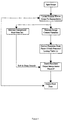
- FIG. 1 a flow diagram illustrating an interpolation method according to one embodiment of the invention is shown.
- color channels When dealing with a colored image, separate color channels will be involved, for example cyan, magenta, yellow and black.
- the following description describes the method for one color channel only. The method is duplicated for each color channel and any number of color channels can be accommodated.
- the interpolation method comprises the steps of
- the above method is then repeated by moving to the next local position in the input image for interpolation.
- pixel X and Y are relative terms, meaning that pixel X is sharp relative to pixel Y and pixel Y is soft relative to pixel X.
- pixel X' is sharp relative to a pixel Y', but both X' and Y' may be sharp relative to another set of pixels X" and Y" in another application.
- a 4x4 kernel of coefficients is convolved with the input image. For each output interpolated value, the spatial location of each output pixel in relation to the input pixels determines which specific coefficients are used. The spatial locations of the output pixels are determined by the desired interpolation factors specified for each of two output dimensions.
- Each position of the convolution kernel with reference to the input image is referred to as a "local position" in the input image. For a 4x4 kernel, this "position" is comprised of a 16 pixel area.
- the sharp interpolation algorithm which is used for calculating the sharp interpolated output image pixel X is a two-dimensional digital filter, obtained using a standard filter design method, such as described by R.M. Mersereau (Two Dimensional Digital Signal Processing I, Edited by T.S. Huang, Springer-Verlag, New York 1981, "Two Dimensional Non-Recursive Filter Design”).
- the soft result is calculated by using a smooth filter in the form of a two-dimensional cubic spline with all positive weighting coefficients. This produces a smooth result with no ringing.
- the calculations are carried out by the use of precalculated weighting coefficients, as, for example, described in U.S. Patent 4,578,812 to Yui.
- the sharp and soft results are calculated at identical pixel positions in the output image.
- the image contrast is derived by the use of contrast detector mask coefficients, in the present example, which are stored in memory and are fixed values to detect edges or contrast of an image. These values are: 1/16 1/16 1/16 1/16 1/16 1/16 -15/16 1/16 1/16 1/16 1/16 1/16 1/16 1/16 1/16 1/16 1/16 1/16 1/16 1/16 1/16 1/16 1/16 1/16 1/16 1/16 1/16 1/16 1/16 1/16 1/16 1/16 1/16 1/16 1/16 1/16 1/16 1/16 1/16 1/16 1/16 1/16 1/16 1/16 1/16 1/16 1/16 1/16 1/16 1/16 1/16 1/16 1/16 1/16 1/16 1/16 1/16 1/16 1/16 1/16 1/16 1/16 1/16 1/16 1/16 1/16
- a value for the image density is taken to be proportional to the local average image value, which is approximately represented by the soft interpolated output pixel value Y. This is done for reasons of speed optimization.
- the density measure can be generated in a manner similar to the contrast value above, i.e. by the application of density detector coefficients, if desired.
- the image contrast and density values are each used to reference a one-dimensional lookup table containing input to output relationships, such as those illustrated in Figures 6 to 11, and the resultant table values or weighting factors obtained, each with a value from 0 to 1, are then multiplied to produce the scale factor S.
- the manner in which S is derived from the input image content is application dependent. For example, there may be one or more image characteristics which will influence the sharpness quality of the image. In addition, the number and nature of these characteristics may vary over the image. Therefore, derivation of S is locally adaptive, i.e. by generating image content variables at the local position where interpolation is taking place. Due to the subjective nature of its operation, the manner in which S is derived is ideally also user controllable. For example, in the case of a colored image, density measures are generated for each color channel involved. Rather than scaling these measures to directly generate the factor S for each channel, tables are used to specify the actual desired sharpness for particular density values. For example, it may be desirable to decrease the sharpness of an image in a high density cyan color area, which can be achieved by setting up the lookup table in an appropriate fashion.
- the resultant output pixel P is regarded as an intermediate value and a third interpolated output image pixel W is calculated from the input pixel data.
- One or more additional input image characteristic values are derived, depending on circumstances or requirements, and these additional image characteristic values are used to obtain a second scaling factor S'.
- the intermediate value P may be taken to represent a sharp value, defining the upper end of the sharpness continuum for interpolation
- the third interpolated value W will represent a value appropriate for digital descreening applications, defining a lower boundary of the sharpness continuum.
- X and Y may each be selected from a group of M and N values, respectively: X ⁇ ⁇ X O ..X M ⁇ Y ⁇ ⁇ Y O ..Y N ⁇
- Any one element of each respective space may be selected as X and Y, as determined by global or local image content.
- X can be selected to be a sharp interpolated value and Y can be selected to be a soft interpolated value.
- Algorithms can be used to calculate X and Y to generate values of the desired sharpness or softness which can be prestored in an intermediate buffer.
- Additional interpolation coefficients to generate W would then be prestored in a coefficient buffer.
- the specific algorithms used to generate the interpolation boundaries can vary based upon the image type and subjective requirements. A number of established methods could be used to generate any number of interpolated values. These values can then be combined in the fashion described above to derive a resultant output interpolation result.
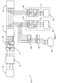
- FIG. 3 a diagrammatical illustration of an interpolation apparatus according to the invention is given.
- three color channels i.e. cyan, magenta and yellow (CMY).
- the interpolation apparatus is generally indicated by reference numeral 10 and comprises an image storage or input buffer 12, a coefficient buffer 14, image convolution interpolation logic 16, an adaptive interpolation algorithm implementation or DSP (Digital Signal Processing) controller 18 and prestored lookup tables 20 for deriving the scaling factor S.
- image convolution interpolation logic image convolution interpolation logic
- DSP Digital Signal Processing
- the DSP controller 18 implements the interpolation algorithm and the input buffer 12, the interpolation logic 16 and the coefficient buffer 14, as well as the lookup tables 20, to provide real-time image interpolation.
- the input buffer 12 is implemented using a number of banks of Static Random Access Memory or SRAM integrated circuit components. Sufficient storage is provided to accommodate a number of lines of the input image.
- the coefficient buffer 14 is implemented using a single bank of Dynamic Random Access Memory or DRAM integrated circuit components.
- the coefficient buffer 14 is used to store pre-calculated interpolation weighting coefficients prior to real-time image interpolation.
- specific sets of values within the memory are accessed for real-time image convolution. The manner in which these values are accessed is controlled by the interpolation logic 16.
- the implementation of the algorithm requires that three types of interpolation values be calculated independently, one for each color channel involved for adaptive selection.
- Figure 4 illustrates a memory segmentation scheme within the coefficient buffer 14 used to accommodate the precalculated coefficients required for the calculations.
- a first memory segment 22 is provided for precalculated weighting coefficients for sharp interpolation
- a second memory segment 24 is provided for coefficients for smooth interpolation
- a third memory segment 26 is provided for contrast detection.
- the smooth interpolated value is also used to approximate a density measurement.
- a fourth memory segment 28 is provided for 100% or one-to-one interpolation, i.e. where no enlargement or reduction of the image takes place. During one-to-one interpolation, the segment 28 is accessed rather than the segments 22, 24 and 26.
- the memory segment 28 is further subdivided into three tables which represent the same types of coefficients as the segments 22, 24 and 26, but without enlargement or reduction. This arrangement provides for added flexibility which allows the image to be sharpened or smoothed while the size remains unaltered.
- the interpolation logic 16 performs the actual image interpolation calculations through a series of convolutions of coefficient weighting factors (using 4x4 kernels) and input image buffer data, such as described, for example, in U.S. Patent No. 4,578,812. However, as speed becomes less of an issue, more accurate interpolation values can be calculated using larger interpolation kernels, e.g. 6x6, etc. Following interpolation, the resulting values are passed to the DSP controller 18 for adaptive selection.
- the prestored lookup tables 20 which are accessible from the DSP controller 18 contain tables each of which describe a relationship between the image contrast or density values and the desired degree of sharpness corresponding to each of those values. A total of six tables are used in the present example where three color channels are involved:
- the interpolation algorithm processes each color channel independently. All contrast, density (or other) interpolated values and derived table scaling factors are individually selectable for each channel.
- the six tables 20 are independent and each describe a relationship between an image characteristic value and a scaling factor, it is possible to expand the implementation to allow for channel interdependencies.
- the three density values could be used to access one of three three-dimensional tables containing the scaling factors. This would allow sharpening in a particular channel based upon the combined densities and thus could isolate particular color areas for smoothing or sharpening.
- Using one-, two-, three- or even four-dimensional tables it will be appreciated that a number of measures or interdependencies could be accommodated.
- controller 18 is implemented in firmware which runs on a Motorola DSP 56001 microcontroller. While real-time hardware provides interpolated data as required, the firmware controls the continuum selection and adaptivity process.
- the implementation comprises two modules:
- weighting factors referred to in steps 3 and 4 above are derived from lookup or reference tables for two reasons:
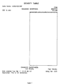
- Figure 6 illustrates a lookup table where full output image sharpness is independent of local image contrast. Therefore, the sharpness setting is global, in this particular instance.
- the graph illustrates the degree of image sharpness versus contrast and it is divided into two halves: the left side denoting "undershoot” or “negative overshoot” or “black fringe” contrast, and the right side denoting "overshoot” or “positive overshoot” or “white fringe” contrast.
- the horizontal scale denotes the degree of contrast, low to high, for each type of overshoot.
- the vertical scale denotes the degree of sharpness running from full smoothness (or “enhanced smoothness") to full sharpness (or “enhanced sharpness”). It should be noted that the degree of sharpness is relative and also depends on the sharpness versus density relationship, i.e. there is also a density lookup table, such as the table shown in Figure 7, which will be used in conjunction with this table.
- Figure 7 shows a lookup table representing the degree of output image sharpness corresponding to density.
- the horizontal scale denotes the degree of density, low to high, plotted against a vertical scale which denotes the degree of sharpness running from full smoothness to full sharpness.
- the degree of sharpness is relative and also depends on the sharpness versus contrast relationship.
- a contrast table will be used in conjunction with this table, e.g. the table shown in Figure 6.
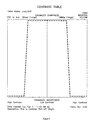
- Figure 8 illustrates a lookup table with sharpness reduction at high contrast in both the black and white fringe areas.
- the density table, for use in association with this table can be identical to Figure 7 if full sharpness denoted in this graph for the lower contrast areas is the maximum sharpness available from the interpolation.
- Application of this lookup table will result in full enhanced sharpness, except in higher contrast regions, which will be enhanced to full smoothness. This is useful in reducing high contrast ringing or fringing.
- Figure 9 is similar to Figure 8 except that only the lower contrast black fringe regions are enhanced in sharpness. All other regions are softened. This is useful in reducing the low contrast noise while preserving or enhancing image sharpness.
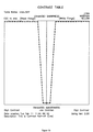
- Figure 10 illustrates a lookup table with enhanced smoothness at low contrast in both black and white fringe regions. All other regions are at enhanced sharpness. This is useful to more effectively reduce white fringing including that which may already exist in the original image, while maintaining image detail or enhancing sharpness.
- the lookup table illustrated in Figure 11 will result in full enhanced sharpness for low density areas. It is useful in reducing high density film and/or input scanner noise.
- the contrast and density lookup tables referred to above will be combined in one lookup table, which is predetermined (usually by the user) and prestored in the interpolator hardware.
- the lookup table will contain two portions: a contrast versus sharpness table and a density versus sharpness table. This enables the two relationships to be treated interdependently.
- FIG. 12 illustrates a color printing installation, generally indicated at 50, incorporating interpolation hardware according to the present invention, in block diagram form.
- the installation 50 comprises an input device, such as a scanner 52, a page composition system 54 for manipulating a scanned image and a color printing device 56.
- the installation 50 also includes proofing devices for viewing intermediate results prior to final printing, such as a monitor 58 (at low resolution), a digital film recorder 60 (at high resolution) and an ink jet printer 62.
- a color transparency which is input into the system is shown at 64.
- the color converters are indicated at 66, 68, 70 and 72 and the interpolators are indicated at 74, 76, 78 and 80.
- the color converter 66 and interpolator 74 are located between the scanner 52 and the page composition system 54 for color transform and interpolation between the RGB and CMYK color spaces.
- the color converters 70 and 72 and the interpolators 78 and 80 are located between the page composition system 54 and the monitor 58 and ink jet printer 62. In all these applications, interpolation is carried out prior to color transformation.
- the converter 68 and interpolator 76 are located between the page composition system 54 and the digital film recorder 60. In this application, interpolation is effected after color conversion so that only three color channels need be contended with during interpolation.
Landscapes
- Physics & Mathematics (AREA)
- Engineering & Computer Science (AREA)
- General Physics & Mathematics (AREA)
- Computational Mathematics (AREA)
- Mathematical Analysis (AREA)
- Mathematical Optimization (AREA)
- Pure & Applied Mathematics (AREA)
- Theoretical Computer Science (AREA)
- Data Mining & Analysis (AREA)
- Mathematical Physics (AREA)
- Databases & Information Systems (AREA)
- Software Systems (AREA)
- General Engineering & Computer Science (AREA)
- Algebra (AREA)
- Image Processing (AREA)
- Facsimile Image Signal Circuits (AREA)
- Apparatus For Radiation Diagnosis (AREA)
- Closed-Circuit Television Systems (AREA)
- Television Systems (AREA)
- Editing Of Facsimile Originals (AREA)
Claims (33)
- Verfahren zum Verarbeiten eines digitalen Eingabebildes in ein interpoliertes digitales Ausgabebild, das die Schritte umfaßt:(a) Erhalten von Pixeldaten des Eingabebildes;(b) Auswählen einer lokalen Position innerhalb des Eingabebildes zur Interpolation;(c) Berechnen eines ersten interpolierten Ausgabebildpixels an einer vorbestimmten Pixelposition in dem Ausgabebild unter Verwendung eines ersten interpolierenden Algorithmuses;(d) Berechnen eines zweiten interpolierten Ausgabebildpixels an der vorbestimmten Pixelposition in dem Ausgabebild unter Verwendung eines zweiten interpolierenden Algorithmuses;(e) Berechnen eines für das Eingabebild charakteristischen Werts unter Verwendung der Eingabepixeldaten und eines Satzes von Gewichtungskoeffizienten, die repräsentativ sind für ein vorbestimmtes Merkmal des Eingabebildes; und(f) Berechnen eines resultierenden Ausgabebildpixels an der vorbestimmten Pixelposition in dem Ausgabebild durch Kombinieren der ersten und zweiten interpolierten Ausgabebildpixel als eine Funktion des für das Eingabebild charakteristischen Werts.
- Verfahren nach Anspruch 1, wobei der für das Eingabebild charakteristische Wert abgeleitet wird von einem Anteil der Eingabepixeldaten, welcher repräsentativ ist für die lokale Position.
- Verfahren nach Anspruch 1, wobei der erste interpolierte Ausgabebildpixel erhalten wird durch die Anwendung eines ersten Interpolationsalgorithmuses, welcher ein verhältnismäßig scharfes Resultat erzeugt, und der zweite interpolierte Ausgabebildpixel erhalten wird durch die Anwendung eines zweiten Interpolations-algorithmuses, welcher ein verhältnismäßig glattes Resultat erzeugt.
- Verfahren nach Anspruch 3, wobei die scharfen und die glatten interpolierten Ausgabebildpixel erhalten werden durch die Anwendung von vorberechneten Gewichtungskoeffizienten, welche von den ersten und den zweiten Interpolationsalgorithmen jeweils erhalten werden.
- Verfahren nach Anspruch 1, welches die weiteren Schritte umfaßt:Erhalten eins dritten interpolierten Ausgabebildpixels an einer vorbestimmten Pixelposition in dem Ausgabebild;Ableiten eines weiteren, für das Eingabebild charakteristischen Werts von den Eingabebildpixeldaten; undBerechnen eines weiteren resultierenden Ausgabebildpixels bei der vorbestimmten Pixelposition in dem Ausgabebild durch Kombinieren des ersten resultierenden Ausgabebildpixels und des dritten interpolierten Ausgabebildpixels als eine Funktion des weiteren für das Eingabebild charakteristischen Werts.
- Verfahren nach Anspruch 5, wobei der resultierende Ausgabebildpixel berechnet wird gemäß dem Algorithmus:
 P den resultierenden Ausgabebildpixel repräsentiert;X den ersten interpolierten Ausgabebildpixel repräsentiert;Y den zweiten interpolierten Ausgabebildpixel repräsentiert; undS einen Skalierungsfaktor mit einem Wert aus dem Bereich von 0 bis 1 repräsentiert, welcher von dem für das Eingabebild charakteristischen Wert abgeleitet ist,und wobei
der weitere resultierende Ausgabebildpixel berechnet wird unter Verwendung des Algorithmuses: P' den weiteren resultierenden Ausgabebildpixel repräsentiert;W den dritten interpolierten Ausgabebildpixel repräsentiert undS' einen weiteren Skalierungsfaktor mit einem Wert aus dem Bereich von 0 bis 1 repräsentiert, welcher abgeleitet wird von dem weiteren für das Eingabebild charakteristischen Wert.
 - Verfahren nach Anspruch 1, wobei von den ersten und zweiten interpolierten Ausgabebildpixeln jeder erhalten wird durch Auswahl aus einem Satz von jeweils vorberechneten ersten und zweiten interpolierten Ausgabebildpixeln.
- Verfahren nach Anspruch 3, wobei der resultierende Ausgabebildpixel berechnet wird gemäß dem Algorithmus:
 P den resultierenden Ausgabebildpixel repräsentiert;X den ersten oder scharf interpolierten Ausgabebildpixel repräsentiert;Y den zweiten oder glatt interpolierten Ausgabebildpixel repräsentiert; undS einen Skalierungsfaktor mit einem Wert aus dem Bereich von 0 bis 1 repräsentiert, welcher abgeleitet wird von dem für das Eingabebild charakteristischen Wert.
 - Verfahren nach Anspruch 8, wobei das Eingabebild ein farbiges Bild ist, welches eine Anzahl von Grundfarben aufweist, und weiter den Schritt des Bereitstellens einer vieldimensionalen Nachschlagtabelle umfaßt, wobei die Anzahl der Dimension mit der Anzahl der Grundfarben korrespondiert, wobei die Nachschlagtabelle für das Eingabebild charakteristische Werte für jede einzelne der Grundfarben auf einen korrespondierenden Wert für den Skalierungsfaktor abbildet.
- Verfahren nach Anspruch 9, wobei die Anzahl der Grundfarben drei ist.
- Verfahren nach Anspruch 9, wobei die Anzahl der Grundfarben vier ist.
- Verfahren nach Anspruch 8, wobei der Skalierungsfaktor S abgeleitet wird von zwei getrennten für das Eingabebild charakteristischen Werten.
- Verfahren nach Anspruch 12, wobei die zwei getrennten für das Eingabebild charakteristischen Werte Eingabebildkontrast und Eingabebilddichte an der lokalen Position in dem Eingabebild umfassen.
- Verfahren nach Anspruch 13, wobei der Eingabebildkontrast aus den Eingabebilddaten erzeugt wird durch Falten eines Satzes von Kontrast-Gewichtungskoeffizienten mit den Eingabebilddaten.
- Verfahren nach Anspruch 14, wobei die Eingabebilddichte als proportional zu dem verhältnismäßig glatt interpolierten Ausgabebildpixel genommen wird.
- Verfahren nach Anspruch 14, wobei die Eingabebilddichte abgeleitet wird von den Eingabebilddaten.
- Verfahren nach Anspruch 12, welches weiter umfaßt den Schritt des Bereitstellens von Nachschlagtabellen, welche die für das Eingabebild charakteristischen Werte abbilden auf korrespondierende Werte für den Skalierungsfaktor.
- Verfahren nach Anspruch 17, wobei die Nachschlagtabellen zwei eindimensionale Nachschlagtabellen umfassen, die Eingabebildkontrast und -dichte jeweils auf korrespondierende Zwischenwerte für den Skalierungsfaktor abbilden und das Verfahren weiter den Schritt des Zusammenmultiplizierens der Zwischenwerte umfaßt, um den Skalierungsfaktor zu erzeugen.
- Verfahren nach Anspruch 1, wobei der für das Eingabebild charakteristische Wert den Eingabebildkontrast umfaßt.
- Verfahren nach Anspruch 1, wobei der für das Eingabebild charakteristische Wert die Eingabebilddichte umfaßt.
- Verfahren nach Anspruch 1, welches weiter den Schritt der Ableitung eines zweiten für das Bild charakteristischen Werts aus den Eingabepixeldaten und Berechnen des resultierenden Ausgabepixels durch Kombinieren der ersten und zweiten Ausgabebildpixel als eine Funktion der ersten und zweiten für das Bild charakteristischen Werte umfaßt.
- Verfahren nach Anspruch 21, wobei die ersten und zweiten charakteristischen Werte Werte umfassen, die jeweils Bildkontrast und -dichte repräsentieren.
- Verfahren nach Anspruch 1, welches weiter umfaßt die Schritte des Ausfindigmachens einer zweiten lokalen Position innerhalb des Eingabebilds; des Wiederholens der Schritte (c) bis (f), um einen weiteren resultierenden Ausgabebildpixel zu erhalten; und des Wiederholens der Schritte für weitere lokale Position, bis ein vollständiges interpoliertes Ausgabebild einer erforderlichen Größe erzeugt ist.
- Vorrichtung zur Verarbeitung von digitalen Bildern zum Interpolieren eines digitalen Eingabebilds in ein interpoliertes Ausgabebild, welche umfaßt:einen Eingabepuffer (12) zum Unterbringen von Pixeldaten des Eingabebilds;einen Koeffizientenpuffer (14) zum Speichern von vorberechneten Interpolations-Gewichtungskoeffizienten vor einer Echtzeit-Bildinterpolation und welche umfaßt ein erstes Speichersegment (22) zur Aufnahme eines ersten Satzes von vorberechneten Interpolations-Gewichtungskoeffizienten, die durch Verwendung eines ersten interpolierenden Algorithmuses erhalten werden; ein zweites Speichersegment (24) zum Aufnehmen eines zweiten Satzes von vorberechneten Gewichtungskoeffizienten, welche zur Verwendung eines zweiten interpolierenden Algorithmuses erhalten werden; und ein drittes Speichersegment (26) zum Aufnehmen eines Satzes von vorberechneten Gewichtungskoeffizienten, die repräsentativ sind für ein vorbestimmtes Merkmal des Eingabebildes;Bildfaltungs- und Interpolationsmittel (16,18) zum Berechnen eines ersten interpolierten Ausgabebildpixels unter Verwendung der Eingabepixeldaten und des ersten Satzes von Gewichtungskoeffizienten, und zum Berechnen eines zweiten interpolierten Ausgabebildpixels unter Verwendung der Eingabepixeldaten und des zweiten Satzes von Gewichtungskoeffizienten, und zum Berechnen eines Wertes für das Bildmerkmal unter Verwendung der Eingabepixeldaten und des für das Bild charakteristischen Gewichtungskoeffizienten, und zum Berechnen eines resultierenden Ausgabepixels durch Kombinieren der ersten und zweiten Ausgabebildpixel als eine Funktion des charakteristischen Werts.
- Vorrichtung nach Anspruch 24, wobei der Koeffizientenpuffer weiter ein viertes Speichersegment (28) zum Aufnehmen von vorberechneten Interpolations-koeffizienten zum Erreichen konstanter Interpolationskoeffizienten zum Erreichen konstanter Bildgrößeninterpolation umfaßt.
- Vorrichtung nach Anspruch 24, wobei der erste interpolierte Ausgabebildpixel erhalten wird durch die Anwendung des ersten Interpolationsalgorithmuses, welcher ein verhältnismäßig scharfes Resultat erzeugt, und der zweite interpolierte Ausgabebildpixel erhalten wird durch die Anwendung des zweiten Interpolationsalgorithmuses, der ein verhältnismäßig glattes Resultat erzeugt.
- Vorrichtung nach Anspruch 26, wobei der resultierende Ausgabebildpixel berechnet wird gemäß dem Algorithmus:
 P den resultierenden Ausgabebildpixel repräsentiert;X den ersten oder scharf interpolierten Ausgabebildpixel repräsentiert;Y den zweiten oder glatt interpolierten Ausgabebildpixel repräsentiert; undS einen Skalierungsfaktor mit einem Wert aus dem Bereich von 0 bis 1 repräsentiert, welcher abgeleitet wird von dem für das Eingabebild charakteristischen Wert.
 - Vorrichtung nach Anspruch 27, wobei die Mittel zum Ableiten eines Eingabebildmerkmals angepaßt sind, um Werte für Bildkontrast und Bilddichte abzuleiten.
- Vorrichtung nach Anspruch 28, die weiter Nachschlagtabellen (20) zum Erhalten des Skalierungsfaktors S als eine Funktion der Bildkontrast- und Bilddichtewerte umfaßt.
- Vorrichtung nach Anspruch 29, die weiter einen Koeffizientenpuffer umfaßt, der einen Satz von Kontrastdetektormaskenkoeffizienten zum Ableiten der Bildkontrastwerte enthält.
- Vorrichtung nach Anspruch 24, die weiter Mittel zum Erhalten eines dritten interpolierten Ausgabebildpixels an der vorbestimmten Pixelposition in dem Ausgabebild umfaßt;Mittel zum Ableiten eines weiteren für das Eingabebild charakteristischen Werts aus den Eingabebildpixeldaten; undMittel zum Berechnen eines weiteren resultierenden Ausgabebildpixels an der vorbestimmten Pixelposition in dem Ausgabebild durch Kombinieren des ersten resultierenden Ausgabebildpixels und des dritten interpolierten Ausgabebildpixels als eine Funktion des weiteren für das Eingabebild charakteristischen Werts.
- Vorrichtung nach Anspruch 31, wobei der resultierende Ausgabebildpixel berechnet wird gemäß dem Algorithmus:
 P den resultierenden Ausgabebildpixel repräsentiert;X den ersten interpolierten Ausgabebildpixel repräsentiert; undY den zweiten interpolierten Ausgabebildpixel repräsentiert; undS einen Skalierungsfaktor mit einem Wert aus dem Bereich von 0 bis 1 repräsentiert, der aus dem ersten für das Eingabebild charakteristischen Wert abgeleitet wird,und wobei der weiter resultierende Ausgabebildpixel berechnet wird unter Verwendung des Algorithmuses:
- Vorrichtung nach Anspruch 24, die weiter einen Puffer umfaßt, der einen Satz der ersten interpolierten Ausgabebildpixel und einen Satz der zweiten interpolierten Ausgabebildpixel zum Zugreifen durch die Mittel zum Erhalten der ersten und zweiten interpolierten Ausgabebildpixel zum Auswählen eines Wertes aus jedem einzelnen der Sätze enthält.
Applications Claiming Priority (3)
| Application Number | Priority Date | Filing Date | Title |
|---|---|---|---|
| US841681 | 1992-02-26 | ||
| US07/841,681 US5327257A (en) | 1992-02-26 | 1992-02-26 | Method and apparatus for adaptively interpolating a digital image |
| PCT/CA1993/000072 WO1993017394A1 (en) | 1992-02-26 | 1993-02-22 | Method and apparatus for adaptively interpolating a digital image |
Publications (2)
| Publication Number | Publication Date |
|---|---|
| EP0632914A1 EP0632914A1 (de) | 1995-01-11 |
| EP0632914B1 true EP0632914B1 (de) | 1997-02-05 |
Family
ID=25285462
Family Applications (1)
| Application Number | Title | Priority Date | Filing Date |
|---|---|---|---|
| EP93903764A Expired - Lifetime EP0632914B1 (de) | 1992-02-26 | 1993-02-22 | Verfahren und gerät zur adaptiven interpolation eines digitalen bildes |
Country Status (8)
| Country | Link |
|---|---|
| US (1) | US5327257A (de) |
| EP (1) | EP0632914B1 (de) |
| AT (1) | ATE148799T1 (de) |
| AU (1) | AU3489793A (de) |
| DE (1) | DE69308017T2 (de) |
| DK (1) | DK0632914T3 (de) |
| ES (1) | ES2097491T3 (de) |
| WO (1) | WO1993017394A1 (de) |
Families Citing this family (55)
| Publication number | Priority date | Publication date | Assignee | Title |
|---|---|---|---|---|
| JP3217398B2 (ja) * | 1991-08-09 | 2001-10-09 | キヤノン株式会社 | 画像読取装置 |
| JPH05336365A (ja) * | 1992-05-28 | 1993-12-17 | Canon Inc | 画像形成装置 |
| JPH0640080A (ja) * | 1992-07-24 | 1994-02-15 | Brother Ind Ltd | プリンタ |
| JPH10509824A (ja) * | 1994-11-23 | 1998-09-22 | イメイション・コーポレイション | 画像データの適応的補間のためのシステム及び方法 |
| US5687300A (en) * | 1995-03-27 | 1997-11-11 | Linotype-Hell Ag | Process for creating five to seven color separations used on a multicolor press |
| US5793379A (en) * | 1995-04-03 | 1998-08-11 | Nvidia Corporation | Method and apparatus for scaling images having a plurality of scan lines of pixel data |
| US5917963A (en) * | 1995-09-21 | 1999-06-29 | Canon Kabushiki Kaisha | Image processing apparatus and image processing method |
| JP3753197B2 (ja) * | 1996-03-28 | 2006-03-08 | 富士写真フイルム株式会社 | 画像データの補間演算方法およびその方法を実施する装置 |
| GB2314477A (en) * | 1996-06-19 | 1997-12-24 | Quantel Ltd | Image magnification processing system employing non-linear interpolation |
| US5883629A (en) * | 1996-06-28 | 1999-03-16 | International Business Machines Corporation | Recursive and anisotropic method and article of manufacture for generating a balanced computer representation of an object |
| US5956468A (en) * | 1996-07-12 | 1999-09-21 | Seiko Epson Corporation | Document segmentation system |
| US5844663A (en) * | 1996-09-13 | 1998-12-01 | Electronic Systems Engineering Co. | Method and apparatus for sequential exposure printing of ultra high resolution digital images using multiple multiple sub-image generation and a programmable moving-matrix light valve |
| US5828467A (en) * | 1996-10-02 | 1998-10-27 | Fuji Xerox Co., Ltd. | Block noise prevention by selective interpolation of decoded image data |
| US6115137A (en) * | 1996-12-06 | 2000-09-05 | Canon Kabushiki Kaisha | Image processing system, digital camera, and printing apparatus |
| US5995682A (en) * | 1997-03-19 | 1999-11-30 | Eastman Kodak Company | Method for resizing of a digital image |
| US5867606A (en) * | 1997-08-12 | 1999-02-02 | Hewlett-Packard Company | Apparatus and method for determining the appropriate amount of sharpening for an image |
| US6028969A (en) * | 1997-10-28 | 2000-02-22 | Sharp Laboratories Of America, Inc. | System and method of additive interpolation for affine transformations |
| US6801339B1 (en) * | 1998-03-26 | 2004-10-05 | Fuji Photo Film Co., Ltd. | Image processing method and apparatus |
| US6510254B1 (en) | 1998-04-06 | 2003-01-21 | Seiko Epson Corporation | Apparatus and method for image data interpolation and medium on which image data interpolation program is recorded |
| US6222641B1 (en) * | 1998-07-01 | 2001-04-24 | Electronics For Imaging, Inc. | Method and apparatus for image descreening |
| US6252576B1 (en) | 1998-08-06 | 2001-06-26 | In-System Design, Inc. | Hardware-efficient system for hybrid-bilinear image scaling |
| US6654510B1 (en) | 1998-10-14 | 2003-11-25 | Konica Corporation | Image processing method and image processing system |
| US6154761A (en) * | 1999-02-12 | 2000-11-28 | Sony Corporation | Classified adaptive multiple processing system |
| US6906708B1 (en) * | 1999-03-26 | 2005-06-14 | Canon Kabushiki Kaisha | Image processing method and apparatus, and storage medium |
| US7405740B1 (en) * | 2000-03-27 | 2008-07-29 | Stmicroelectronics, Inc. | Context sensitive scaling device and method |
| EP1180743B1 (de) * | 2000-04-24 | 2007-11-07 | Seiko Epson Corporation | Vorrichtung und Verfahren zur Interpolation von Bilddaten |
| US6718074B1 (en) | 2000-06-02 | 2004-04-06 | Cognex Corporation | Method and apparatus for inspection for under-resolved features in digital images |
| US6856704B1 (en) * | 2000-09-13 | 2005-02-15 | Eastman Kodak Company | Method for enhancing a digital image based upon pixel color |
| US7003173B2 (en) * | 2001-06-12 | 2006-02-21 | Sharp Laboratories Of America, Inc. | Filter for combined de-ringing and edge sharpening |
| US7116841B2 (en) | 2001-08-30 | 2006-10-03 | Micron Technology, Inc. | Apparatus, method, and product for downscaling an image |
| ATE453903T1 (de) * | 2001-12-21 | 2010-01-15 | Ibm | Verfahren und schaltungen zur bildskalierung mit hilfe neuronaler netzwerke |
| EP1321896B1 (de) * | 2001-12-21 | 2009-12-30 | International Business Machines Corporation | Verfahren und Schaltungen zur Bildskalierung mit Hilfe neuronaler Netzwerke |
| JP3825403B2 (ja) * | 2002-01-07 | 2006-09-27 | 株式会社リコー | 画像形成装置 |
| US20030169353A1 (en) * | 2002-03-11 | 2003-09-11 | Renato Keshet | Method and apparatus for processing sensor images |
| US7149369B2 (en) * | 2002-04-23 | 2006-12-12 | Hewlett-Packard Development Company, L.P. | Method and system for image scaling |
| JP4196782B2 (ja) * | 2003-08-26 | 2008-12-17 | セイコーエプソン株式会社 | 画像処理装置及び画像処理をコンピュータに実行させる画像処理プログラム |
| US7391933B2 (en) * | 2003-10-30 | 2008-06-24 | Samsung Electronics Co., Ltd. | Method and apparatus for image interpolation based on adaptive polyphase filters |
| JP3833212B2 (ja) * | 2003-11-19 | 2006-10-11 | シャープ株式会社 | 画像処理装置、画像処理プログラムおよび可読記録媒体 |
| US8260087B2 (en) * | 2007-01-22 | 2012-09-04 | Sharp Laboratories Of America, Inc. | Image upsampling technique |
| US8457193B2 (en) * | 2007-09-28 | 2013-06-04 | Intel Corporation | No-reference video quality model |
| SG162641A1 (en) * | 2008-12-31 | 2010-07-29 | St Microelectronics Asia | System and process for imate rescaling using adaptive interpolation kernel with sharpness and overshoot control |
| US20110298972A1 (en) | 2010-06-04 | 2011-12-08 | Stmicroelectronics Asia Pacific Pte. Ltd. | System and process for image rescaling using adaptive interpolation kernel with sharpness and de-ringing control |
| TWI453695B (zh) * | 2010-09-07 | 2014-09-21 | Realtek Semiconductor Corp | 影像處理方法及應用其之電路 |
| CN102413269B (zh) * | 2010-09-21 | 2014-03-05 | 瑞昱半导体股份有限公司 | 视频处理方法及应用该方法的电路 |
| US8520971B2 (en) * | 2010-09-30 | 2013-08-27 | Apple Inc. | Digital image resampling |
| JP5741011B2 (ja) | 2011-01-26 | 2015-07-01 | 株式会社リコー | 画像処理装置、画素補間方法およびプログラム |
| US9524733B2 (en) * | 2012-05-10 | 2016-12-20 | Google Inc. | Objective speech quality metric |
| US10471617B2 (en) | 2015-01-26 | 2019-11-12 | Crayola Llc | Pixel art crayon and marker photo array assembly and kit |
| US10118436B2 (en) | 2015-01-26 | 2018-11-06 | Crayola, Llc | Pixel art crayon and marker photo array assembly and kit |
| WO2016152602A1 (ja) * | 2015-03-23 | 2016-09-29 | 富士フイルム株式会社 | 音響波画像生成装置およびその制御方法 |
| EP4200847A4 (de) | 2020-08-24 | 2024-10-02 | FD IP & Licensing LLC | Vorvisualisierungsvorrichtungen und -systeme für die filmindustrie |
| US12254551B2 (en) | 2022-07-13 | 2025-03-18 | Fd Ip & Licensing Llc | Method and application for animating computer generated images |
| GB2623071B (en) * | 2022-09-30 | 2024-12-11 | Imagination Tech Ltd | Adaptive sharpening for blocks of pixels |
| US20240135507A1 (en) * | 2022-09-30 | 2024-04-25 | Imagination Technologies Limited | Upsampling blocks of pixels |
| US11875492B1 (en) * | 2023-05-01 | 2024-01-16 | Fd Ip & Licensing Llc | Systems and methods for digital compositing |
Family Cites Families (5)
| Publication number | Priority date | Publication date | Assignee | Title |
|---|---|---|---|---|
| US4193092A (en) * | 1978-06-21 | 1980-03-11 | Xerox Corporation | Image interpolation system |
| US4712141A (en) * | 1985-03-30 | 1987-12-08 | Dainippon Screen Mfg. Co., Ltd. | Method and apparatus for interpolating image signals |
| US5038388A (en) * | 1989-05-15 | 1991-08-06 | Polaroid Corporation | Method for adaptively sharpening electronic images |
| JPH04501625A (ja) * | 1989-08-28 | 1992-03-19 | イーストマン・コダック・カンパニー | 重なり平面近似に基づく輝度及び色光度のデジタルイメージノイズ減少 |
| JP3003799B2 (ja) * | 1990-03-28 | 2000-01-31 | 富士写真フイルム株式会社 | 画像の鮮鋭度強調方法及びその装置 |
-
1992
- 1992-02-26 US US07/841,681 patent/US5327257A/en not_active Expired - Lifetime
-
1993
- 1993-02-22 WO PCT/CA1993/000072 patent/WO1993017394A1/en not_active Ceased
- 1993-02-22 DE DE69308017T patent/DE69308017T2/de not_active Expired - Fee Related
- 1993-02-22 ES ES93903764T patent/ES2097491T3/es not_active Expired - Lifetime
- 1993-02-22 AU AU34897/93A patent/AU3489793A/en not_active Abandoned
- 1993-02-22 EP EP93903764A patent/EP0632914B1/de not_active Expired - Lifetime
- 1993-02-22 AT AT93903764T patent/ATE148799T1/de not_active IP Right Cessation
- 1993-02-22 DK DK93903764.4T patent/DK0632914T3/da active
Also Published As
| Publication number | Publication date |
|---|---|
| DE69308017D1 (de) | 1997-03-20 |
| US5327257A (en) | 1994-07-05 |
| WO1993017394A1 (en) | 1993-09-02 |
| AU3489793A (en) | 1993-09-13 |
| DE69308017T2 (de) | 1997-08-28 |
| DK0632914T3 (da) | 1997-08-18 |
| ATE148799T1 (de) | 1997-02-15 |
| ES2097491T3 (es) | 1997-04-01 |
| EP0632914A1 (de) | 1995-01-11 |
Similar Documents
| Publication | Publication Date | Title |
|---|---|---|
| EP0632914B1 (de) | Verfahren und gerät zur adaptiven interpolation eines digitalen bildes | |
| US6771835B2 (en) | Two-dimensional non-linear interpolation system based on edge information and two-dimensional mixing interpolation system using the same | |
| US5818975A (en) | Method and apparatus for area selective exposure adjustment | |
| US5426517A (en) | Automated tone correction apparatus and method using filtered histogram equalization | |
| US6990249B2 (en) | Image processing methods and image processing apparatus | |
| EP1107181B1 (de) | Einstellung des Kontrastes eines digitalen Bildes mit einem adaptiven, rekursiven Digitalfilter | |
| US6058248A (en) | Computerized method for improving data resolution | |
| US5111285A (en) | Video printer device | |
| US20030189579A1 (en) | Adaptive enlarging and/or sharpening of a digital image | |
| US6714688B1 (en) | Method and apparatus for enhancing the edge contrast of an interpolated digital image | |
| US7177481B2 (en) | Multiresolution unsharp image processing apparatus | |
| DE69928775T2 (de) | Verfahren und vorrichtung zur interpolation von bilddaten sowie medium für ein bilddateninterpolationsprogramm | |
| US6275605B1 (en) | Method for adjusting the tone scale of a digital image | |
| EP1024454B1 (de) | Verfahren zur Erhaltung eines räumlichen Details bei der Anwendung einer multidimensionalen Transformation für ein digitales Farbbild | |
| EP0814429A2 (de) | Bildverarbeitungssystem | |
| DE69835333T2 (de) | Tetraheaedrische und geschnitten-tetrahaedrische Interpolationsvorrichtung | |
| JP3965302B2 (ja) | 空間フィルタリング処理方法 | |
| US6714210B1 (en) | Continuous kernel image interpolation | |
| JPH05120416A (ja) | 色変換装置 | |
| JP2000270208A (ja) | 画像処理装置及び画像処理方法 | |
| EP0631249A1 (de) | Bilddatenverarbeitungssystem | |
| DE69830460T2 (de) | Vereinfachte Hardwareimplementation für radiale und Tetraeder-Interpolation | |
| JPH0546750A (ja) | 色変換方法および色変換装置 | |
| JP3059287B2 (ja) | 2値画像変倍装置 | |
| JP3835059B2 (ja) | カラー画像処理方法およびその装置 |
Legal Events
| Date | Code | Title | Description |
|---|---|---|---|
| PUAI | Public reference made under article 153(3) epc to a published international application that has entered the european phase |
Free format text: ORIGINAL CODE: 0009012 |
|
| 17P | Request for examination filed |
Effective date: 19940926 |
|
| AK | Designated contracting states |
Kind code of ref document: A1 Designated state(s): AT BE CH DE DK ES FR GB GR IE IT LI LU MC NL PT SE |
|
| GRAG | Despatch of communication of intention to grant |
Free format text: ORIGINAL CODE: EPIDOS AGRA |
|
| 17Q | First examination report despatched |
Effective date: 19960418 |
|
| GRAH | Despatch of communication of intention to grant a patent |
Free format text: ORIGINAL CODE: EPIDOS IGRA |
|
| GRAH | Despatch of communication of intention to grant a patent |
Free format text: ORIGINAL CODE: EPIDOS IGRA |
|
| GRAA | (expected) grant |
Free format text: ORIGINAL CODE: 0009210 |
|
| AK | Designated contracting states |
Kind code of ref document: B1 Designated state(s): AT BE CH DE DK ES FR GB GR IE IT LI LU MC NL PT SE |
|
| PG25 | Lapsed in a contracting state [announced via postgrant information from national office to epo] |
Ref country code: LI Free format text: LAPSE BECAUSE OF FAILURE TO SUBMIT A TRANSLATION OF THE DESCRIPTION OR TO PAY THE FEE WITHIN THE PRESCRIBED TIME-LIMIT Effective date: 19970205 Ref country code: GR Free format text: LAPSE BECAUSE OF FAILURE TO SUBMIT A TRANSLATION OF THE DESCRIPTION OR TO PAY THE FEE WITHIN THE PRESCRIBED TIME-LIMIT Effective date: 19970205 Ref country code: CH Free format text: LAPSE BECAUSE OF FAILURE TO SUBMIT A TRANSLATION OF THE DESCRIPTION OR TO PAY THE FEE WITHIN THE PRESCRIBED TIME-LIMIT Effective date: 19970205 Ref country code: BE Effective date: 19970205 Ref country code: AT Effective date: 19970205 |
|
| REF | Corresponds to: |
Ref document number: 148799 Country of ref document: AT Date of ref document: 19970215 Kind code of ref document: T |
|
| REG | Reference to a national code |
Ref country code: CH Ref legal event code: EP |
|
| PG25 | Lapsed in a contracting state [announced via postgrant information from national office to epo] |
Ref country code: LU Free format text: LAPSE BECAUSE OF NON-PAYMENT OF DUE FEES Effective date: 19970228 |
|
| REG | Reference to a national code |
Ref country code: IE Ref legal event code: FG4D Free format text: 71980 |
|
| REF | Corresponds to: |
Ref document number: 69308017 Country of ref document: DE Date of ref document: 19970320 |
|
| REG | Reference to a national code |
Ref country code: ES Ref legal event code: FG2A Ref document number: 2097491 Country of ref document: ES Kind code of ref document: T3 |
|
| PG25 | Lapsed in a contracting state [announced via postgrant information from national office to epo] |
Ref country code: IE Free format text: LAPSE BECAUSE OF NON-PAYMENT OF DUE FEES Effective date: 19970405 |
|
| ITF | It: translation for a ep patent filed | ||
| PG25 | Lapsed in a contracting state [announced via postgrant information from national office to epo] |
Ref country code: SE Effective date: 19970505 Ref country code: PT Effective date: 19970505 |
|
| PGFP | Annual fee paid to national office [announced via postgrant information from national office to epo] |
Ref country code: DK Payment date: 19970512 Year of fee payment: 5 |
|
| PGFP | Annual fee paid to national office [announced via postgrant information from national office to epo] |
Ref country code: ES Payment date: 19970522 Year of fee payment: 5 |
|
| ET | Fr: translation filed | ||
| REG | Reference to a national code |
Ref country code: CH Ref legal event code: PL |
|
| REG | Reference to a national code |
Ref country code: DK Ref legal event code: T3 |
|
| PG25 | Lapsed in a contracting state [announced via postgrant information from national office to epo] |
Ref country code: MC Effective date: 19970831 |
|
| PLBE | No opposition filed within time limit |
Free format text: ORIGINAL CODE: 0009261 |
|
| STAA | Information on the status of an ep patent application or granted ep patent |
Free format text: STATUS: NO OPPOSITION FILED WITHIN TIME LIMIT |
|
| 26N | No opposition filed | ||
| PG25 | Lapsed in a contracting state [announced via postgrant information from national office to epo] |
Ref country code: ES Free format text: LAPSE BECAUSE OF EXPIRATION OF PROTECTION Effective date: 19980223 |
|
| PG25 | Lapsed in a contracting state [announced via postgrant information from national office to epo] |
Ref country code: DK Free format text: LAPSE BECAUSE OF NON-PAYMENT OF DUE FEES Effective date: 19980302 |
|
| PGFP | Annual fee paid to national office [announced via postgrant information from national office to epo] |
Ref country code: GB Payment date: 19990219 Year of fee payment: 7 |
|
| PGFP | Annual fee paid to national office [announced via postgrant information from national office to epo] |
Ref country code: FR Payment date: 19990226 Year of fee payment: 7 |
|
| PGFP | Annual fee paid to national office [announced via postgrant information from national office to epo] |
Ref country code: NL Payment date: 19990228 Year of fee payment: 7 |
|
| PGFP | Annual fee paid to national office [announced via postgrant information from national office to epo] |
Ref country code: DE Payment date: 19990326 Year of fee payment: 7 |
|
| PG25 | Lapsed in a contracting state [announced via postgrant information from national office to epo] |
Ref country code: GB Free format text: LAPSE BECAUSE OF NON-PAYMENT OF DUE FEES Effective date: 20000222 |
|
| REG | Reference to a national code |
Ref country code: ES Ref legal event code: FD2A Effective date: 20000301 |
|
| REG | Reference to a national code |
Ref country code: DK Ref legal event code: EBP |
|
| PG25 | Lapsed in a contracting state [announced via postgrant information from national office to epo] |
Ref country code: NL Free format text: LAPSE BECAUSE OF NON-PAYMENT OF DUE FEES Effective date: 20000901 |
|
| GBPC | Gb: european patent ceased through non-payment of renewal fee |
Effective date: 20000222 |
|
| PG25 | Lapsed in a contracting state [announced via postgrant information from national office to epo] |
Ref country code: FR Free format text: LAPSE BECAUSE OF NON-PAYMENT OF DUE FEES Effective date: 20001031 |
|
| NLV4 | Nl: lapsed or anulled due to non-payment of the annual fee |
Effective date: 20000901 |
|
| PG25 | Lapsed in a contracting state [announced via postgrant information from national office to epo] |
Ref country code: DE Free format text: LAPSE BECAUSE OF NON-PAYMENT OF DUE FEES Effective date: 20001201 |
|
| REG | Reference to a national code |
Ref country code: FR Ref legal event code: ST |
|
| PG25 | Lapsed in a contracting state [announced via postgrant information from national office to epo] |
Ref country code: IT Free format text: LAPSE BECAUSE OF NON-PAYMENT OF DUE FEES Effective date: 20050222 |