EP0632965B2 - Procédé et dispositif de traitement des produits en morceaux à plusieurs stades avec des fluides de traitement - Google Patents
Procédé et dispositif de traitement des produits en morceaux à plusieurs stades avec des fluides de traitement Download PDFInfo
- Publication number
- EP0632965B2 EP0632965B2 EP94110243A EP94110243A EP0632965B2 EP 0632965 B2 EP0632965 B2 EP 0632965B2 EP 94110243 A EP94110243 A EP 94110243A EP 94110243 A EP94110243 A EP 94110243A EP 0632965 B2 EP0632965 B2 EP 0632965B2
- Authority
- EP
- European Patent Office
- Prior art keywords
- treatment
- individual
- individual chambers
- chamber
- chambers
- Prior art date
- Legal status (The legal status is an assumption and is not a legal conclusion. Google has not performed a legal analysis and makes no representation as to the accuracy of the status listed.)
- Expired - Lifetime
Links
Images


Classifications
-
- A—HUMAN NECESSITIES
- A23—FOODS OR FOODSTUFFS; TREATMENT THEREOF, NOT COVERED BY OTHER CLASSES
- A23B—PRESERVATION OF FOODS, FOODSTUFFS OR NON-ALCOHOLIC BEVERAGES; CHEMICAL RIPENING OF FRUIT OR VEGETABLES
- A23B2/00—Preservation of foods or foodstuffs, in general
- A23B2/20—Preservation of foods or foodstuffs, in general by heating materials in packages which are progressively transported, continuously or stepwise, through the apparatus
- A23B2/28—Preservation of foods or foodstuffs, in general by heating materials in packages which are progressively transported, continuously or stepwise, through the apparatus with packages on a revolving platform
-
- A—HUMAN NECESSITIES
- A23—FOODS OR FOODSTUFFS; TREATMENT THEREOF, NOT COVERED BY OTHER CLASSES
- A23B—PRESERVATION OF FOODS, FOODSTUFFS OR NON-ALCOHOLIC BEVERAGES; CHEMICAL RIPENING OF FRUIT OR VEGETABLES
- A23B2/00—Preservation of foods or foodstuffs, in general
- A23B2/20—Preservation of foods or foodstuffs, in general by heating materials in packages which are progressively transported, continuously or stepwise, through the apparatus
-
- A—HUMAN NECESSITIES
- A61—MEDICAL OR VETERINARY SCIENCE; HYGIENE
- A61L—METHODS OR APPARATUS FOR STERILISING MATERIALS OR OBJECTS IN GENERAL; DISINFECTION, STERILISATION OR DEODORISATION OF AIR; CHEMICAL ASPECTS OF BANDAGES, DRESSINGS, ABSORBENT PADS OR SURGICAL ARTICLES; MATERIALS FOR BANDAGES, DRESSINGS, ABSORBENT PADS OR SURGICAL ARTICLES
- A61L2/00—Disinfection or sterilisation of materials or objects, in general; Accessories therefor
- A61L2/02—Disinfection or sterilisation of materials or objects, in general; Accessories therefor using physical processes
- A61L2/04—Heat
- A61L2/06—Hot gas
-
- A—HUMAN NECESSITIES
- A61—MEDICAL OR VETERINARY SCIENCE; HYGIENE
- A61L—METHODS OR APPARATUS FOR STERILISING MATERIALS OR OBJECTS IN GENERAL; DISINFECTION, STERILISATION OR DEODORISATION OF AIR; CHEMICAL ASPECTS OF BANDAGES, DRESSINGS, ABSORBENT PADS OR SURGICAL ARTICLES; MATERIALS FOR BANDAGES, DRESSINGS, ABSORBENT PADS OR SURGICAL ARTICLES
- A61L2/00—Disinfection or sterilisation of materials or objects, in general; Accessories therefor
- A61L2/24—Apparatus using programmed or automatic operation
Definitions
- the invention relates to a method for treating lumpy products by means of process media in As part of a sequence of procedural steps (treatment stages) in a treatment unit. It also relates on a corresponding device for treating lumpy products by means of a supply unit Process media as part of a sequence of process steps (treatment stages) in one Treatment unit.
- This prior art describes a so-called large-capacity autoclave, which is used to carry out most Treatment methods in which negative pressure or harmful media predominate are used.
- This large-capacity autoclave has a relatively large lockable chamber, in which those to be treated Products are introduced in batches.
- Such single-chamber autoclaves with which the batch process is used are in the purchase and the larger they are built, the cheaper it is to operate.
- the purchase because the chamber is enlarged and the unit is cheaper than the realization of several small autoclave systems; in operation because at thermal polarity reversal, the system mass to be reversed in several small autoclaves is greater than with a large autoclave.
- the level of automation customary today is the organizational and personnel costs are greater than for the large-capacity autoclave.
- the continuous systems mostly work according to a 3-phase system: preheating - sterilizing - cooling, the individual processes generally take place in different, interconnected, stationary chambers, which can be arranged in the form of a tower, i.e. each product goes through each treatment stage in succession in another chamber (treatment center).
- Another disadvantage is that the same sterilization medium is always used in such a system must become.
- Another multi-chamber system has become known from DE 35 07 337 C2. It shows a procedure as well an associated device for coating substrates as part of a sequence of process steps.
- Each process step (treatment stage) is provided with a group of treatment containers that are both linear can also be arranged circularly.
- a transport system that includes a transport chamber with a lock has, the substrates after the treatment with process step "n" from the container of the associated Group discharged into the transport chamber and from there into a container of the group, the process step "n + 1" is assigned, introduced.
- the known system therefore requires a time-consuming and material-consuming transport and lock system. It is also specially designed for coating substrates.
- the invention is based on the object, the method described at the outset and the corresponding device so that - while maintaining the batch mode of operation - the product quality is improved, buffer stores largely eliminated and despite maintaining the batch mode of operation, a quasi-continuous treatment is possible.
- a chain of at least one treatment unit three separate treatment units are formed, in which the lumpy products for the duration of the The sequence of process steps remains that in the chain, divided into the individual treatment units, the individual process steps of the sequence run simultaneously, that the sequence of process steps in the Individual treatment units of the chain or in groups thereof, starting at a predetermined time, and that the time offset (clock) is predetermined by a common control unit.
- the treatment unit consists of a plurality consists of at least three separate individual treatment units, each with at least one inflow and outflow for which have process media, and in which the lumpy products for the duration of the sequence of process steps remain that the inflows and outflows of the individual treatment units are connected to the supply unit in such a way that the chain, divided into the individual treatment units, the individual process steps of the sequence run at the same time that a common control or regulating unit is provided, which is constructed and with the individual treatment units is linked to the sequence of process steps in the individual treatment units of the chain or groups thereof, starts at a predetermined time interval.
- the common control unit is preferably mechanical in the form of a transport system for the individual treatment units formed, which transports the individual treatment units to different locations in which at least one treatment stage is carried out, and the start of treatment by the location of the respective Chamber defined or the treatment units as a common control unit is a clocked drive order to generate a gradual movement of the individual treatment units with a characteristic Number of stops in which specific treatment steps take place, with connection systems are provided for the process media, which are firmly connected on one side to a stationary supply unit and on the other hand with the inflow and outflow of the individual treatment units stop station-specific can be brought into active engagement, so that the individual treatment units in the stop stations of the fixed supply unit, depending on the position, with the process media required for the respective treatment level are acted upon.
- an individual treatment unit is first in the first holding station formed, for example a certain amount of products to be treated in a first single chamber locked in. Then this single unit, for example the single chamber, moves to the next (second) Stop station, where the next process step is carried out, for example "preheating". At the same time the content of the subsequent individual unit is unloaded in the first holding station and filled with new goods. in the next time cycle said first individual unit moves to the next, the third holding station, the second individual unit to the second holding station, etc. After the complete passage, the treated goods can be removed.
- the products are in many small individual treatment units during their treatment housed, i.e. a single unit has fewer products than comparatively in the one-room large-capacity autoclave.
- the treatment continues in each individual unit according to the above mentioned batch process, for the total of the individual units, however, the more continuous shift register process results and even a quasi fully continuous mode of operation for the media supply units.
- the products enter the device individually and regularly and leave them with the same after the treatment Frequency. Since the products are preferably in lockable chambers during their treatment, treatment methods can be used that require lockability relative to the system environment. These methods include, for example, treatments for negative or positive pressure or treatments with media, that must not leak into the environment.
- the required product buffers are smaller by at least the factor that the number of individual treatment units, corresponds in particular to the individual chambers compared to an equally productive large-capacity autoclave.
- the number of products that are treated together as a batch in a single chamber is different from that Large capacity autoclave reduced. This ensures the uniformity of the media flow in relation to the products, i.e. Generally, the reproducibility of the physical conditions in the autoclave single chamber is generally higher than with the large-capacity autoclave. This results in less oversizing of the treatment process and thus increased productivity with improved product quality.
- the treatment sections take place individually and at different times in the invention, all treatment sections continuously and simultaneously, but at different times. Because the associated Units in the supply unit are operated continuously, they are smaller and cheaper than in the large-capacity autoclave, where the units only have to be operated temporarily, but then with higher output. In terms of control technology, the continuously operated units work more evenly in the invention and more reproducible than the discontinuously operated units of the large-capacity autoclave.
- An important further advantage of the invention is the fact that, with comparable technical outlay, it is process-dependent the energy consumption compared to the large-capacity autoclave can be significantly reduced. This depends et al on the smaller and continuously operated units with optimum efficiency.
- Another advantage is the increased productivity with smooth operation.
- An important advantage of the invention is the practical feasibility of partial energy recovery Treatment procedures that include cooling and heating processes.
- the cooling media heat up when it cools down of the products, chambers and pipelines and can be continuously transferred to another treatment station be used to heat the products.
- the heating and cooling processes are in the large-capacity autoclave however apart in time and large amounts of media and energy would have to be buffered until they are reused become, which would result in correspondingly higher investment costs for the plant.
- each product (or a small range of products) is in a single interchangeable treatment unit, for example In one chamber, it is possible to have different products in different at the same time Sterilize chambers (regardless of whether they are liquid, solid, granulated, open, packaged, etc.). Every chamber Different treatment, in particular sterilization media can also be supplied in the same cycle, since each chamber has its own feed line. For example, a chamber can be flushed with hot steam a following but e.g. with aqueous citric acid. Nevertheless, the entire system does not have to be on that other sterilization medium can be switched. Other operations could also be switched on, e.g. Pickling, coating, cleaning etc.
- a particularly favorable construction of the device results when the individual treatment units, in particular the individual chambers are of the same design. This also simplifies the maintenance of the system and lowers the manufacturing costs.
- the individual treatment units for example the individual chambers, can be in a linear chain be moved to the starting point with a quick return of the chamber that has undergone the last treatment step. It is advisable to provide an additional single chamber and each at the starting point in bring a parking position so that it can be coupled into the chain immediately before the returning chamber on The starting point is, which then takes the parking position.
- the individual treatment units For example, the individual chambers are arranged in a ring and the clocked drive arrangement one Has rotary drive, i.e. procedurally transported the goods to be treated with its individual unit all round becomes.
- Figure 1 shows an autoclave device for multi-stage treatment of lumpy products by means of flowing Media.
- the autoclave consists of a plurality of individual chambers 1, 1a, 1b, etc., in the present embodiment 36 chambers are provided.
- the number of chambers is determined, among other things. according to the number of treatment steps, the necessary buffering, the number of cycles, the space available etc.
- the individual chambers are arranged in a ring on a bogie and are gradually, i.e. each by a chamber width (1/36 revolution), as will be explained in more detail with reference to FIG. 2.
- Each individual chamber represents a substantially rectangular pressure vessel with a door 17 which can be closed tightly.
- the basic structure of the individual chambers will be discussed in more detail later with reference to FIGS. 3 and 4.
- each Single chamber has an inflow and outflow 2, 3, for the process media and the generation of pressure or vacuum, which are led to a central rotary feed 4, the structure of which is explained in more detail with reference to FIG. 5.
- Each chamber place i.e. a holding station is assigned to each chamber position, in which position-specific process flows occur.
- the holding station I in which the individual chamber 1 is currently located, is the discovery Unloading assigned to the chambers.
- a stationary mechanism (not shown) takes over here the automatic opening and closing of the chamber door.
- the holding station I, the loading station is also a commercially available one Handling device 5 in the form of an industrial robot for loading and unloading the products 6 in batches into the respective individual chamber located in the holding station I, in FIG. 1 in the chamber 1, assigned.
- the treatment cycle begins or ends with the loading and unloading of the products, whereby a system can have several such stops.
- a transport device 7 brings those to be treated Products 6 from the outside of the plant to the loading station, while a transport device 8 handles the Brings products out of the area of the plant.
- the handling device 5 removes the products 6 individually or in small groups when loading the individual chamber (in example 3) from the transport device 7 or in the same way transfers the products 6 to the transport device during unloading 8th.
- loading and unloading can also be done manually.
- the autoclave system works continuously.
- the supply unit combines the media periphery and the control in a common housing.
- the media periphery includes all the necessary units for the preparation and distribution of the process and auxiliary media between the media lines of the house network connection and the media lines for the rotary feed.
- control includes all devices for sequence control, for switching electrical and pneumatic control Consumers, sensors, evaluation and control devices, operating software, system cabling and a Control panel with its switches, display devices and recorders.
- the supply unit 10 and the connection systems 9 are constructed from known means and can by a person skilled in process engineering can be set up and connected in the usual way without further information.
- the units of the supply unit work continuously.
- the timely loading of the chambers with the correct medium is supplied via the rotary feeder 4. It mediates the transition of the media from the fixed one Supply unit 10 or from the connection system 9 firmly connected to the rotating individual chambers.
- the rotary feed basically consists of two parts, namely a rotor in the form of a sliding disk 23, which is rigidly connected to the individual chambers 1, 1a, etc. via the lines 2, 3 is and rotates with them and a stator in the form of sliding rings 24 which are fixed to the connection systems 9 are connected, i.e. are stationary.
- the sliding disc (the rotor) has a hole for connections 2 and 3 of each individual chamber, through which the Media can flow into and out of the chamber.
- the slide rings (the stator) point for each process media connection of the connection systems 9 one or more elongated hole zones 25 (FIG. 7) in order to allow a free passage to create the holes in the rotating sliding washer for the passage of the process medium.
- the location of the Holes and the elongated hole zones is chosen so that each individual chamber in the respective holding station with those there required process media is supplied or activated in the necessary manner.
- the rotary feeder therefore contains the media switching program, which means that control with valves is largely possible eliminated.
- FIG. 2 shows a section through the annular chamber arrangement according to FIG. 1 at an arbitrary point, ie through the individual chamber 1n and the opposite individual chamber 1n + 17 .
- the individual chambers rest on a bogie 12 which is carried and moved by the rotary cycle drive in the form of a rotary indexing table 13.
- rotary indexing tables are commercially available and ensure the necessary cycle times and the required division accuracy when the individual chambers are moved step by step.
- the entire interior of the annulus is provided with a cover 12a (see also FIG. 1), in order to To give the plant a closed external image and to protect the other parts of the plant.
- connection systems 9 open into ring lines 9a, 9b etc., which in turn via hose lines 14 and connecting piece 15 are connected to the sliding rings of the rotary feed 4.
- the connections of the chambers are in turn guided on nozzles 16, which on the rotor of the rotary feed or on those located therein Holes are attached. This routing is shown schematically in the right part of Figure 2.
- connection types shown are only examples.
- the specialist has a wide variety of options here and sub-variants are available.
- FIGS. 3 and 4 show details in the structure of the individual chambers, which are preferably of identical design.
- 3 shows a longitudinal section through the individual chamber 1 n with the door 17 closed
- FIG. 4 shows a front view with the door open.
- Each individual chamber represents an essentially rectangular pressure vessel with a door that can be closed tightly.
- the interior of the individual chamber is divided into compartments 18, with a ribbed plate resting on the compartment floor.
- the products 6, of which a group of three is shown, lie on the ribbed plate.
- the ribbed plates are arranged alternately offset from compartment to compartment (see FIG. 3) and in this way bring about a meandering flow of the process media and the flow of the products through the process media on all sides.
- the ribbed plates also make it possible to load and unload the products into the compartments using fork-shaped grippers.
- Each individual chamber has connections 2, 3, 19-22 which, like FIG. 2 (in connection with FIG. 5), are schematic shows, are guided to the sliding plate 23 of the rotary feed 4.
- the two large-lumen connections 2 and 3 serve as process connections for the process media.
- the small-lumen process connection 19 has the task of deriving Chamber condensate.
- the connections 20 and 21 supply the coil heating of the individual compartments with heating steam and drain off the condensate.
- the connection 22 supplies the door actuation, for example by Compressed air.
- FIGS. 5-7 show details of the rotary feed 4 of FIGS. 1 and 2.
- FIG. 5 shows an enlarged one Section through the (upper) center of Figure 2.
- Figure 6 is an enlarged section of the figure 5 in the area of interaction between the rotor and stator of the rotary feed.
- FIG. 7 in turn shows a top view of a sliding ring of the stator.
- the connecting pieces 16, to which the connections of the individual chambers (FIG. 3) are guided open in the sliding washer 23 or in the bores therein.
- the nozzle 15, according to Figure 2 via hose lines 14 are connected to the ring lines 9a ff.
- connection systems 9 open into slide rings 24 or in therein elongated hole zones 25, which can be seen particularly well from FIG. 7 in the top view of a slide ring are.
- Spring-biased components 26 provide the necessary pressure of the rotor on the stator, so that the process media cannot exit from the side. It is expedient to provide sealing systems in this sliding area, for which various options are available to the expert.
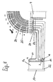
- FIG. 8 shows a "circuit diagram" for the method described in the table below for a more detailed explanation of the "interconnection" of the chambers with the connection systems 9 via the rotary feed.
- 8 shows a single chamber 1 n with door 17 and connections 2, 3 and 19-22 (see FIG. 3), which are firmly connected to the sliding plate 23.
- Six sliding rings 24 are shown and designated G1-G6.
- these slide rings with their elongated hole zones 25 are practically folded up as a top view, with the assignment of the individual elongated hole zones to the treatment steps, called phases. Ultimately, these phases also correspond to the individual stops.
- the table shows the phases in the first column, overall in accordance with those selected in the exemplary embodiment Number of chambers 36 phases.
- the second column shows which treatment or procedural steps the individual phases assigned.
- the other columns show which process media in the individual process steps over the elongated hole zones of the slide rings - and thus according to Figure 8 - into the associated connections of the Single chambers - flow.
- phase 01 i.e. in the loading station I (see FIG. 1) via the slide ring 6 at the connection 22 (see FIG. 8) creates a vacuum, i.e. the chamber door 17 opens.
- Heating steam is applied to the Connection 20 of the coil heating switched; the condensate is connected via connection 21 and the slide ring G5 deducted.
- the device according to FIG. 1 not only has interchangeable chambers on, but connector connections, so that during a sterilization process z.
Landscapes
- Life Sciences & Earth Sciences (AREA)
- Engineering & Computer Science (AREA)
- Health & Medical Sciences (AREA)
- Wood Science & Technology (AREA)
- Zoology (AREA)
- Chemical & Material Sciences (AREA)
- Food Science & Technology (AREA)
- Polymers & Plastics (AREA)
- Epidemiology (AREA)
- Animal Behavior & Ethology (AREA)
- General Health & Medical Sciences (AREA)
- Public Health (AREA)
- Veterinary Medicine (AREA)
- Apparatus For Disinfection Or Sterilisation (AREA)
- Food Preservation Except Freezing, Refrigeration, And Drying (AREA)
- Physical Or Chemical Processes And Apparatus (AREA)
Claims (8)
- Procédé pour le traitement de produits en morceaux à l'aide de milieux de processus industriels dans le cadre d'une succession d'étapes opératoires (étapes de traitement) dans une unité de traitement, comprenant les étapes consistant à :à titre d'unité de traitement, on forme une chaíne de chambres individuelles sous la forme d'un anneau de cercle, chambres dans lesquelles viennent se loger les produits en morceaux en formant une petite charge et y restent pendant la durée de la succession des étapes opératoires,dans la chaíne, subdivisée en chambres individuelles séparées, les étapes opératoires individuelles de la succession se déroulent de manière simultanée,la succession des étapes opératoires dans les chambres individuelles de la chaíne respectivement dans des groupes de ces dernières, commence de manière décalée dans le temps, dans un cycle prédéfini, etle décalage dans le temps (le cycle) est prédéfini par une unité commune de commande respectivement de réglage.
- Procédé selon la revendication 1, caractérisé en ce que l'unité de commande commune est réalisée, du point de vue mécanique, sous la forme d'un système de transport pour les chambres individuelles, qui transporte les chambres individuelles à différents endroits dans lesquels on effectue respectivement au moins une étape de traitement, et en ce que le début du traitement est déterminé par l'endroit de la chambre individuelle respective.
- Procédé selon la revendication 1, caractérisé en ce que les chambres individuelles sont transportées plus loin au cours du traitement et le décalage dans le temps du début du traitement est en outre déterminé par une unité commune de commande respectivement de réglage pour les milieux de processus industriels.
- Procédé selon la revendication 2, caractérisé en ce que les chambres individuelles sont transportées successivement pas à pas aux endroits de traitement et en ce que la chaíne est formée par des chambres individuelles, en chargeant respectivement une nouvelle chambre individuelle lorsque la chambre individuelle chargée précédente a été transportée à l'étape de traitement suivante et en déchargeant une chambre individuelle traitée lorsque la chambre individuelle suivante a été transportée en direction de la dernière étape de traitement.
- Dispositif pour le traitement de produits en morceaux (6) à l'aide de milieux de processus industriels qui peuvent être prélevés d'une unité d'alimentation (10) dans le cadre d'une succession d'étapes opératoires (étapes de traitement) dans une unité de traitement, caractériséen ce que l'unité de traitement est constituée par une multitude d'au moins trois chambres individuelles (1, 1a, 1b) séparées, disposées en une chaíne sous la forme d'un anneau de cercle, chambres qui présentent respectivement au moins une entrée et une sortie (2, 3) pour les milieux de processus industriels, dans lesquelles les produits en morceaux (6) viennent se loger en formant une petite charge et y restent pendant la durée de la succession des étapes opératoires,en ce que les entrées et les sorties (2, 3) des chambres individuelles sont reliées à l'unité d'alimentation (10) de telle sorte que, dans la chaíne subdivisée en chambres individuelles séparées, les étapes opératoires individuelles de la succession se déroulent de manière simultanée,en ce qu'on prévoit une unité commune de commande respectivement de réglage (12, 13) qui est conçue et qui est reliée aux chambres individuelles (1, 1a, 1b) de telle sorte que la succession des étapes opératoires dans les chambres individuelles de la chaíne respectivement dans des groupes de ces dernières, commence de manière décalée dans le temps, dans un cycle prédéfini.
- Dispositif selon la revendication 5, caractérisé en ce queon attribue aux chambres individuelles (1, 1a, 1b), à titre d'unité de commande commune, un ordre de commande cyclique (12, 13) pour l'obtention d'un mouvement pas à pas des chambres individuelles avec un nombre caractéristique de postes d'arrêt (I, II, III), dans lesquelles se déroulent des étapes de traitement spécifiques, eton prévoit des systèmes de liaison (9) pour les milieux de processus industriels qui d'une part,0 sont reliés à demeure à une unité d'alimentation fixe (10) et qui d'autre part, peuvent être amenés en engrènement de travail, de manière spécifique à un poste d'arrêt, avec l'entrée et la sortie (2, 3) des chambres individuelles, de telle sorte que les chambres individuelles dans les postes d'arrêt peuvent être chargées avec les milieux de processus industriels requis pour l'étape de traitement respective, en fonction de la position par rapport à l'unité d'alimentation fixe.
- Dispositif selon la revendication 5 ou 6, caractérisé en ce que les chambres individuelles (1, 1a, 1b) sont disposées sous la forme d'un anneau de cercle en étant montées sur une plate-forme tournante (12) et l'ordre de commande cyclique présente un système de commande rotative (12, 13).
- Dispositif selon la revendication 7, caractérisé en ce que, pour le chargement, qui dépend de la position, des chambres individuelles (1, 1a, 1b) avec des milieux de processus industriels, on prévoit une alimentation rotative (4) qui présente d'une part, un stator (24) dans lequel sont pratiquées des ouvertures (25) qui sont reliées à demeure aux systèmes de liaison (9) et qui présente d'autre part, un rotor (23) dans lequel sont pratiquées des ouvertures qui sont reliées à demeure avec la plate-forme tournante (12) et qui mènent aux entrées et sorties (2, 3) des chambres individuelles, et en ce que les ouvertures pratiquées dans le stator et dans le rotor sont adaptées l'une par rapport à l'autre en ce qui concerne leur position dans l'espace de telle sorte que, en fonction de l'angle de rotation, respectivement le contrôle des processus industriels des systèmes de liaison (9), requis pour le traitement, est relié aux entrées et aux sorties des chambres individuelles se trouvant dans les postes d'arrêt correspondants.
Applications Claiming Priority (2)
| Application Number | Priority Date | Filing Date | Title |
|---|---|---|---|
| DE4322467A DE4322467C1 (de) | 1993-07-06 | 1993-07-06 | Verfahren zum mehrstufigen Behandeln von stückigen Produkten mittels Prozeßmedien und Vorrichtung zur Durchführung des Verfahrens |
| DE4322467 | 1993-07-06 |
Publications (3)
| Publication Number | Publication Date |
|---|---|
| EP0632965A1 EP0632965A1 (fr) | 1995-01-11 |
| EP0632965B1 EP0632965B1 (fr) | 1998-06-17 |
| EP0632965B2 true EP0632965B2 (fr) | 2002-03-20 |
Family
ID=6492085
Family Applications (1)
| Application Number | Title | Priority Date | Filing Date |
|---|---|---|---|
| EP94110243A Expired - Lifetime EP0632965B2 (fr) | 1993-07-06 | 1994-07-01 | Procédé et dispositif de traitement des produits en morceaux à plusieurs stades avec des fluides de traitement |
Country Status (6)
| Country | Link |
|---|---|
| US (1) | US5522724A (fr) |
| EP (1) | EP0632965B2 (fr) |
| JP (1) | JPH07171380A (fr) |
| BR (1) | BR9402601A (fr) |
| DE (2) | DE4322467C1 (fr) |
| ES (1) | ES2119933T5 (fr) |
Cited By (1)
| Publication number | Priority date | Publication date | Assignee | Title |
|---|---|---|---|---|
| DE102005046446B3 (de) * | 2005-09-29 | 2006-12-28 | MPH Mess-, Prüf- und Handling-Systeme GmbH | Vorrichtung zur Prüfung von Sensoren |
Families Citing this family (6)
| Publication number | Priority date | Publication date | Assignee | Title |
|---|---|---|---|---|
| DE29611297U1 (de) * | 1996-06-28 | 1996-09-05 | Rico-Maschinenbau Max Appel KG, 73431 Aalen | Pasteurisiervorrichtung |
| DE19646024C2 (de) * | 1996-11-08 | 1999-07-22 | Alge High Future Gmbh | Verfahren und Vorrichtung zur Sterilisation medizinischer Instrumente |
| GB2326817B (en) * | 1997-07-04 | 2001-04-18 | Univ Sheffield | Cleaning apparatus |
| DE19816221A1 (de) | 1998-04-09 | 1999-10-21 | Siemens Ag | Verfahren und Vorrichtung zum Behandeln von Gegenständen, vorzugsweise Wafern |
| DE102016119745B4 (de) * | 2016-10-17 | 2020-01-23 | Miwe Michael Wenz Gmbh | Dichtungssystem für Türen von Backöfen oder ähnlichem |
| EP3909615A1 (fr) * | 2020-05-13 | 2021-11-17 | Grifols Worldwide Operations Limited | Système et procédé de remplissage stérile de récipients |
Family Cites Families (13)
| Publication number | Priority date | Publication date | Assignee | Title |
|---|---|---|---|---|
| FR1313179A (fr) * | 1961-11-13 | 1962-12-28 | Stein & Roubaix | Perfectionnements au chauffage des métaux à haute température |
| US3809529A (en) * | 1971-07-28 | 1974-05-07 | Ferro Corp | Endless furnace |
| JPS534356B2 (fr) * | 1972-07-06 | 1978-02-16 | ||
| SE400027B (sv) * | 1974-12-02 | 1978-03-13 | Electrolux Ab | Anordning vid en med overtryck arbetande autoklav |
| US4094633A (en) * | 1976-06-14 | 1978-06-13 | Food Processes, Inc. | Granular bed roaster construction |
| DK148817C (da) * | 1979-02-05 | 1986-04-28 | Cabinplant As | Apparat til kontinuerlig kogning af faste emner, navnlig foedevarer |
| GB2055289B (en) * | 1979-08-01 | 1983-09-14 | American Sterilizer Co | Cleaning and biocidal treatment of articles |
| JPS58217625A (ja) * | 1982-06-09 | 1983-12-17 | Daido Steel Co Ltd | 熱処理装置 |
| JPS60184678A (ja) * | 1984-03-02 | 1985-09-20 | Canon Inc | 真空処理装置 |
| GB8528902D0 (en) * | 1985-11-23 | 1986-01-02 | Greaves & Sons Ltd J W | Treatment of expansible materials |
| GB8805705D0 (en) * | 1988-03-10 | 1988-04-07 | Farleydene Ltd | Improvements in/relating to autoclaves |
| JPH01252886A (ja) * | 1988-03-31 | 1989-10-09 | Central Glass Co Ltd | 熱加工炉並びにそれによる熱処理方法 |
| NL8902792A (nl) * | 1989-11-10 | 1991-06-03 | Stork Amsterdam | Werkwijze en inrichting voor het toevoeren van blikken aan continu sterilisator. |
-
1993
- 1993-07-06 DE DE4322467A patent/DE4322467C1/de not_active Expired - Lifetime
-
1994
- 1994-06-30 BR BR9402601A patent/BR9402601A/pt not_active IP Right Cessation
- 1994-07-01 DE DE59406255T patent/DE59406255D1/de not_active Expired - Lifetime
- 1994-07-01 EP EP94110243A patent/EP0632965B2/fr not_active Expired - Lifetime
- 1994-07-01 ES ES94110243T patent/ES2119933T5/es not_active Expired - Lifetime
- 1994-07-06 US US08/267,894 patent/US5522724A/en not_active Expired - Lifetime
- 1994-07-06 JP JP6155068A patent/JPH07171380A/ja active Pending
Cited By (1)
| Publication number | Priority date | Publication date | Assignee | Title |
|---|---|---|---|---|
| DE102005046446B3 (de) * | 2005-09-29 | 2006-12-28 | MPH Mess-, Prüf- und Handling-Systeme GmbH | Vorrichtung zur Prüfung von Sensoren |
Also Published As
| Publication number | Publication date |
|---|---|
| DE4322467C1 (de) | 1995-03-02 |
| ES2119933T5 (es) | 2002-11-01 |
| ES2119933T3 (es) | 1998-10-16 |
| JPH07171380A (ja) | 1995-07-11 |
| EP0632965A1 (fr) | 1995-01-11 |
| BR9402601A (pt) | 1995-04-04 |
| US5522724A (en) | 1996-06-04 |
| EP0632965B1 (fr) | 1998-06-17 |
| DE59406255D1 (de) | 1998-07-23 |
Similar Documents
| Publication | Publication Date | Title |
|---|---|---|
| DE2624156C1 (de) | Einrichtung zur Behandlung von flachen Werkstücken mit Strömungsitteln | |
| WO1998033605A1 (fr) | Installation de nettoyage industriel | |
| DE68907508T2 (de) | Verfahren und Vorrichtung zum Sterilisieren von Deckeln. | |
| DE3780687T2 (de) | System fuer saubere luft. | |
| DE2712020A1 (de) | Dekontaminationsanlage fuer chirurgische instrumente u.dgl. | |
| DE4031472A1 (de) | Vorrichtung zum sterilisieren, fuellen und verschliessen einer fuelloeffnung | |
| DE102006036475A1 (de) | Verfahren zur Sterilisation von Reinräumen für die Behandlung und/oder das Füllen und Verschließen von Behältern | |
| EP0632965B2 (fr) | Procédé et dispositif de traitement des produits en morceaux à plusieurs stades avec des fluides de traitement | |
| DE69713157T2 (de) | Verfahren und vorrichtung zum sterilisieren von gegenständen | |
| DE69513574T2 (de) | Anlage zur Massenherstellung essfertiger gekochter Nahrungsmittel von langer Haltbarkeit | |
| DE2509611A1 (de) | Vorrichtung zum sterilen verpacken von guetern in behaelter | |
| DE2454973C3 (de) | Vorrichtung zum Temperatur-Konditionieren von Verformungen aus thermoplastischem Kunststoff | |
| DE3825533A1 (de) | Verfahren und vorrichtung zur innenbehandlung metallener rohre | |
| DE69803925T2 (de) | Methode zur kalt-sterilisation von öfen des tunnel-typs im pharmazeutischen bereich und öfen zur anwendung dieser methode | |
| DE102010002179A1 (de) | Schleuse zum Überführen eines Werkstücks zwischen einem Außenraum und einem Innenraum eines Werkstückbehandlungsbereichs | |
| DE69211051T2 (de) | Trockner für Teigwaren | |
| CH530307A (de) | Anlage zum keimfreien Verpacken eines Füllguts in Behälter | |
| DE2736088A1 (de) | Loesungssterilisationsanlage | |
| DE2810228A1 (de) | Sterilisierapparat fuer in behaelter abgefuellte infusionsloesungen o.dgl. | |
| DE69405809T2 (de) | Kontinuierliche Sterilisation | |
| EP2761052B1 (fr) | Dispositif de transport destiné à transporter plusieurs substrats dans la zone d'un dispositif de traitement de substrat | |
| DE4207896C2 (de) | Verfahren zum Sterilisieren von Hohlkörpern und Vorrichtung zur Durchführung des Verfahrens | |
| DE69402543T2 (de) | Vorrichtung zur herstellung von körpern an festen arbeitsplätzen, die um eine geschlossene, kreisförmige fördereinrichtung angeordnet sind und der die körper zugeführt wurden | |
| EP0430938B1 (fr) | Four de boulangerie | |
| DE3709672A1 (de) | Verfahren und anlage zum reinigen und entfetten von behandlungsgut |
Legal Events
| Date | Code | Title | Description |
|---|---|---|---|
| PUAI | Public reference made under article 153(3) epc to a published international application that has entered the european phase |
Free format text: ORIGINAL CODE: 0009012 |
|
| AK | Designated contracting states |
Kind code of ref document: A1 Designated state(s): BE DE ES FR GB IT NL |
|
| 17P | Request for examination filed |
Effective date: 19950513 |
|
| GRAG | Despatch of communication of intention to grant |
Free format text: ORIGINAL CODE: EPIDOS AGRA |
|
| GRAG | Despatch of communication of intention to grant |
Free format text: ORIGINAL CODE: EPIDOS AGRA |
|
| GRAH | Despatch of communication of intention to grant a patent |
Free format text: ORIGINAL CODE: EPIDOS IGRA |
|
| 17Q | First examination report despatched |
Effective date: 19971126 |
|
| GRAH | Despatch of communication of intention to grant a patent |
Free format text: ORIGINAL CODE: EPIDOS IGRA |
|
| GRAA | (expected) grant |
Free format text: ORIGINAL CODE: 0009210 |
|
| AK | Designated contracting states |
Kind code of ref document: B1 Designated state(s): BE DE ES FR GB IT NL |
|
| GBT | Gb: translation of ep patent filed (gb section 77(6)(a)/1977) |
Effective date: 19980622 |
|
| REF | Corresponds to: |
Ref document number: 59406255 Country of ref document: DE Date of ref document: 19980723 |
|
| ITF | It: translation for a ep patent filed | ||
| REG | Reference to a national code |
Ref country code: ES Ref legal event code: FG2A Ref document number: 2119933 Country of ref document: ES Kind code of ref document: T3 |
|
| ET | Fr: translation filed | ||
| PLBQ | Unpublished change to opponent data |
Free format text: ORIGINAL CODE: EPIDOS OPPO |
|
| PLBI | Opposition filed |
Free format text: ORIGINAL CODE: 0009260 |
|
| PLBF | Reply of patent proprietor to notice(s) of opposition |
Free format text: ORIGINAL CODE: EPIDOS OBSO |
|
| 26 | Opposition filed |
Opponent name: GEA TILL GMBH & CO Effective date: 19990313 |
|
| NLR1 | Nl: opposition has been filed with the epo |
Opponent name: GEA TILL GMBH & CO |
|
| PLBF | Reply of patent proprietor to notice(s) of opposition |
Free format text: ORIGINAL CODE: EPIDOS OBSO |
|
| PLBF | Reply of patent proprietor to notice(s) of opposition |
Free format text: ORIGINAL CODE: EPIDOS OBSO |
|
| PLBF | Reply of patent proprietor to notice(s) of opposition |
Free format text: ORIGINAL CODE: EPIDOS OBSO |
|
| PLBF | Reply of patent proprietor to notice(s) of opposition |
Free format text: ORIGINAL CODE: EPIDOS OBSO |
|
| PLAW | Interlocutory decision in opposition |
Free format text: ORIGINAL CODE: EPIDOS IDOP |
|
| PLAW | Interlocutory decision in opposition |
Free format text: ORIGINAL CODE: EPIDOS IDOP |
|
| REG | Reference to a national code |
Ref country code: GB Ref legal event code: IF02 |
|
| PUAH | Patent maintained in amended form |
Free format text: ORIGINAL CODE: 0009272 |
|
| STAA | Information on the status of an ep patent application or granted ep patent |
Free format text: STATUS: PATENT MAINTAINED AS AMENDED |
|
| 27A | Patent maintained in amended form |
Effective date: 20020320 |
|
| AK | Designated contracting states |
Kind code of ref document: B2 Designated state(s): BE DE ES FR GB IT NL |
|
| GBTA | Gb: translation of amended ep patent filed (gb section 77(6)(b)/1977) | ||
| NLR2 | Nl: decision of opposition | ||
| NLR3 | Nl: receipt of modified translations in the netherlands language after an opposition procedure | ||
| REG | Reference to a national code |
Ref country code: ES Ref legal event code: DC2A Kind code of ref document: T5 Effective date: 20020619 |
|
| NLR2 | Nl: decision of opposition |
Effective date: 20020320 |
|
| REG | Reference to a national code |
Ref country code: DE Ref legal event code: R082 Ref document number: 59406255 Country of ref document: DE Representative=s name: MAI DOERR BESIER PATENTANWAELTE, DE |
|
| PGFP | Annual fee paid to national office [announced via postgrant information from national office to epo] |
Ref country code: GB Payment date: 20130626 Year of fee payment: 20 |
|
| PGFP | Annual fee paid to national office [announced via postgrant information from national office to epo] |
Ref country code: BE Payment date: 20130624 Year of fee payment: 20 |
|
| PGFP | Annual fee paid to national office [announced via postgrant information from national office to epo] |
Ref country code: DE Payment date: 20130621 Year of fee payment: 20 Ref country code: NL Payment date: 20130624 Year of fee payment: 20 Ref country code: ES Payment date: 20130716 Year of fee payment: 20 |
|
| PGFP | Annual fee paid to national office [announced via postgrant information from national office to epo] |
Ref country code: FR Payment date: 20130722 Year of fee payment: 20 |
|
| PGFP | Annual fee paid to national office [announced via postgrant information from national office to epo] |
Ref country code: IT Payment date: 20130628 Year of fee payment: 20 |
|
| REG | Reference to a national code |
Ref country code: DE Ref legal event code: R071 Ref document number: 59406255 Country of ref document: DE |
|
| REG | Reference to a national code |
Ref country code: DE Ref legal event code: R071 Ref document number: 59406255 Country of ref document: DE |
|
| REG | Reference to a national code |
Ref country code: NL Ref legal event code: V4 Effective date: 20140701 |
|
| REG | Reference to a national code |
Ref country code: GB Ref legal event code: PE20 Expiry date: 20140630 |
|
| BE20 | Be: patent expired |
Owner name: *FRESENIUS A.G. Effective date: 20140701 |
|
| PG25 | Lapsed in a contracting state [announced via postgrant information from national office to epo] |
Ref country code: GB Free format text: LAPSE BECAUSE OF EXPIRATION OF PROTECTION Effective date: 20140630 |
|
| PG25 | Lapsed in a contracting state [announced via postgrant information from national office to epo] |
Ref country code: DE Free format text: LAPSE BECAUSE OF EXPIRATION OF PROTECTION Effective date: 20140702 |
|
| REG | Reference to a national code |
Ref country code: ES Ref legal event code: FD2A Effective date: 20141120 |
|
| PG25 | Lapsed in a contracting state [announced via postgrant information from national office to epo] |
Ref country code: ES Free format text: LAPSE BECAUSE OF EXPIRATION OF PROTECTION Effective date: 20140702 |