EP0633055B1 - Rührdeckel für Farbrührmaschine - Google Patents
Rührdeckel für Farbrührmaschine Download PDFInfo
- Publication number
- EP0633055B1 EP0633055B1 EP94401464A EP94401464A EP0633055B1 EP 0633055 B1 EP0633055 B1 EP 0633055B1 EP 94401464 A EP94401464 A EP 94401464A EP 94401464 A EP94401464 A EP 94401464A EP 0633055 B1 EP0633055 B1 EP 0633055B1
- Authority
- EP
- European Patent Office
- Prior art keywords
- collar
- washer
- hub
- bellows
- stirrer
- Prior art date
- Legal status (The legal status is an assumption and is not a legal conclusion. Google has not performed a legal analysis and makes no representation as to the accuracy of the status listed.)
- Expired - Lifetime
Links
- 238000003756 stirring Methods 0.000 title description 3
- 238000007789 sealing Methods 0.000 claims description 5
- 239000004698 Polyethylene Substances 0.000 claims description 3
- -1 polyethylene Polymers 0.000 claims description 3
- 229920000573 polyethylene Polymers 0.000 claims description 3
- 230000000295 complement effect Effects 0.000 claims description 2
- 239000000463 material Substances 0.000 claims description 2
- 239000004033 plastic Substances 0.000 claims description 2
- 229920003023 plastic Polymers 0.000 claims description 2
- 230000000717 retained effect Effects 0.000 claims description 2
- 229920002994 synthetic fiber Polymers 0.000 claims description 2
- 239000003973 paint Substances 0.000 description 4
- 239000003086 colorant Substances 0.000 description 2
- 239000002245 particle Substances 0.000 description 2
- 230000000903 blocking effect Effects 0.000 description 1
- 239000007943 implant Substances 0.000 description 1
- 239000013528 metallic particle Substances 0.000 description 1
- 238000010422 painting Methods 0.000 description 1
- 230000002093 peripheral effect Effects 0.000 description 1
Images
Classifications
-
- B—PERFORMING OPERATIONS; TRANSPORTING
- B01—PHYSICAL OR CHEMICAL PROCESSES OR APPARATUS IN GENERAL
- B01F—MIXING, e.g. DISSOLVING, EMULSIFYING OR DISPERSING
- B01F27/00—Mixers with rotary stirring devices in fixed receptacles; Kneaders
- B01F27/80—Mixers with rotary stirring devices in fixed receptacles; Kneaders with stirrers rotating about a substantially vertical axis
- B01F27/88—Mixers with rotary stirring devices in fixed receptacles; Kneaders with stirrers rotating about a substantially vertical axis with a separate receptacle-stirrer unit that is adapted to be coupled to a drive mechanism
-
- B—PERFORMING OPERATIONS; TRANSPORTING
- B01—PHYSICAL OR CHEMICAL PROCESSES OR APPARATUS IN GENERAL
- B01F—MIXING, e.g. DISSOLVING, EMULSIFYING OR DISPERSING
- B01F35/00—Accessories for mixers; Auxiliary operations or auxiliary devices; Parts or details of general application
- B01F35/30—Driving arrangements; Transmissions; Couplings; Brakes
- B01F35/32—Driving arrangements
- B01F35/323—Driving arrangements for vertical stirrer shafts
- B01F35/3231—Driving several stirrer shafts, e.g. about the same axis
-
- B—PERFORMING OPERATIONS; TRANSPORTING
- B01—PHYSICAL OR CHEMICAL PROCESSES OR APPARATUS IN GENERAL
- B01F—MIXING, e.g. DISSOLVING, EMULSIFYING OR DISPERSING
- B01F35/00—Accessories for mixers; Auxiliary operations or auxiliary devices; Parts or details of general application
- B01F35/40—Mounting or supporting mixing devices or receptacles; Clamping or holding arrangements therefor
- B01F35/42—Clamping or holding arrangements for mounting receptacles on mixing devices
-
- B—PERFORMING OPERATIONS; TRANSPORTING
- B01—PHYSICAL OR CHEMICAL PROCESSES OR APPARATUS IN GENERAL
- B01F—MIXING, e.g. DISSOLVING, EMULSIFYING OR DISPERSING
- B01F35/00—Accessories for mixers; Auxiliary operations or auxiliary devices; Parts or details of general application
- B01F35/45—Closures or doors specially adapted for mixing receptacles; Operating mechanisms therefor
-
- Y—GENERAL TAGGING OF NEW TECHNOLOGICAL DEVELOPMENTS; GENERAL TAGGING OF CROSS-SECTIONAL TECHNOLOGIES SPANNING OVER SEVERAL SECTIONS OF THE IPC; TECHNICAL SUBJECTS COVERED BY FORMER USPC CROSS-REFERENCE ART COLLECTIONS [XRACs] AND DIGESTS
- Y10—TECHNICAL SUBJECTS COVERED BY FORMER USPC
- Y10S—TECHNICAL SUBJECTS COVERED BY FORMER USPC CROSS-REFERENCE ART COLLECTIONS [XRACs] AND DIGESTS
- Y10S366/00—Agitating
- Y10S366/605—Paint mixer
Definitions
- the invention relates to an agitator cover for a painting machine.
- the invention aims to remedy this drawback by proposing an agitator cover, of the type provided with a conventional sealing bellows on the agitator axis bearing on the hub of the cover by its circular upper collar, characterized in that it comprises a support washer for the agitator axis interposed between said hub and bellows collar, this washer being shaped with a surface for receiving the complementary collar of the latter and an opposite surface for application on the hub of the cover, and being provided at least three lugs on said collar receiving surface arranged on the periphery thereof in application, regularly angularly arranged so that it cannot move laterally relative thereto, these lugs being each provided with a notch shaped to receive said collar by clipping, the washer remaining free in rotation retained laterally at the collar by said notches, and in that it is applied e on the hub of the lid under the resilient return of the bellows, being locked in rotation on the hub by a suitable locking means formed on the lid.
- the washer advantageously comprises two opposite circular planar faces, being shaped with dimensions equivalent to those of the bellows collar, which is conventional circular plane.
- This washer is made of plastic, for example polyethylene, whose coefficient of friction with the bellows collar, also made of synthetic material, is low. The wear on the moving moving surfaces is minimal.
- the clip pins can be formed on the outside of the bellows collar or inside. In the latter case, any wear particles, due to the rotation on the latching notches of the lugs, are contained inside the bellows.
- pins are advantageously four in number, distributed circularly ninety degrees from each other on an axis of diameter either slightly greater than that of the collar, or slightly less, apart from play.
- Said means of blocking the washer on the hub advantageously consists of a pin formed or fixed on the cover at the lugs of the washer. This pin abuts on one of the lugs, thus locking the washer in rotation on the hub.
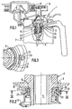
- the cover 1 fitted with a support washer 3 is of the type comprising an agitator axis 5 rotatably mounted on the cover and passing through it perpendicularly in its central part.
- a paint can 7 is fixed to the cover by its lower peripheral edge.
- the cover is mounted suspended by lateral tabs projecting from the machine in a conventional manner and the agitator axis is rotated by means of its upper pinion 9 engaged on a chain 11 moved along the length of the machine.
- This axis has a sealing bellows 13 surrounding its upper part and bearing on the hub of the cover 15.
- the bellows is fixed to the agitator rod by its lower end part 17 and rotates with it. It has at its upper end a flat annular collar 19.
- the washer 3 is a flat annular washer with an internal diameter equivalent to that of the collar 19 and with a slightly larger external diameter. This washer is interposed between the lower central part or hub of the cover and said collar. It is applied under pressure under the elastic return of the bellows upwards on the corresponding flat surface of the hub. It is thin (about 0.5 mm), made of polyethylene as is the bellows. It has four lateral lugs 21 on its periphery arranged at 90 ° from one another and projecting downwards.
- These lugs surround the collar of the low-clearance bellows. They are provided with a lower notch 23 turned inwards at its end and tapered, capable of allowing the mounting of the agitator axis equipped with its bellows on the body of the lid, engaging the washer on the collar of the bellows.
- This operation is carried out manually, in an easy manner, the engagement being facilitated by the internal taper of the notches which promotes reception of the collar.
- the washer being fixed to the collar by its four lugs, it only remains to implant the axis on the body of the cover, the bellows being applied with its support washer to the central hub of the cover.
- the latter comprises (FIG. 3) a tapered pin 25 projecting from the periphery of the applied washer. This pin comes into contact with one of the lugs 21 of the washer, locking it in rotation on the hub 15. The tapering of the pin also promotes reception and positioning of the washer on the hub, avoiding interference from parts.
- the shape of the washer can vary as well as that of the pins, their number, their location outside or inside the washer in relation to the collar, or even on the lower surface for receiving the collar, likewise as the locking element of the washer on the hub which can be obtained in various other ways, for example by a pin of the hub in a groove or a hole of the washer or conversely a pin of the washer on a hole of the cover.
Landscapes
- Chemical & Material Sciences (AREA)
- Chemical Kinetics & Catalysis (AREA)
- Closures For Containers (AREA)
- Accessories For Mixers (AREA)
- Sealing Devices (AREA)
- Coating Apparatus (AREA)
Claims (7)
- Rührdeckel der Art, wie er mit einer klassischen Faltenbalgdichtung (13) auf der Rührachse (5) vorgesehen ist, die auf der Anlagefläche (15) des Deckels über ihren oberen kreisförmigen Hals (19) getragen wird, dadurch gekennzeichnet, daß er eine Abstützscheibe (3) für die Rührachse aufweist, die zwischen der Anlagefläche (15) und dem Hals (19) des Faltenbalgs angeordnet ist, wobei die Scheibe mit einer Aufnahmeoberfläche des Halses, die das Gegenstück zu letzterem ist, und einer gegenüberliegenden Oberfläche für das Aufbringen auf die Anlagefläche des Deckels versehen ist, und wobei er mit mindestens drei Vorsprüngen (21) auf der Aufnahmeoberfläche des Halses versehen ist, die bei der Aufbringung auf dem Umfang des letzteren angeordnet sind, die regelmäßig und im Winkel angeordnet sind, damit sich diese nicht seitlich relativ zu diesem biegen kann, wobei jeder dieser Vorsprünge (21) mit einer Raste (23) versehen ist, die vorgesehen ist, um den Hals (19) eingeklipst aufzunehmen, wobei die Scheibe (3), die seitlich am Hals durch die Rasten (23) gehalten wird, bei der Drehung frei bleibt, und dadurch, daß sie unter der elastischen Spannung des Faltenbalgs (13) auf die Anlagefläche (15) des Deckels aufgebracht wird, wobei sie bei der Drehung durch eine angemessene Blockiervorrichtung (25), die auf dem Deckel ausgebildet ist, auf der Anlagefläche festgehalten wird.
- Rührdeckel nach Anspruch 1, dadurch gekennzeichnet, daß die Scheibe (3) vorteilhafterweise zwei gegenüberliegende kreisförmige ebene Seiten aufweist, die mit Abmessungen versehen sind, die denjenigen des Halses (19) des Faltenbalgs entsprechen, der klassisch kreisförmig flach ist.
- Rührdeckel nach einem der Ansprüche 1, 2, dadurch gekennzeichnet, daß die Scheibe (3) aus Kunststoffmaterial, zum Beispiel aus Polyethylen, besteht, dessen Reibungskoeffizient mit dem Hals des Faltenbalgs, der ebenfalls aus synthetischem Material besteht, niedrig ist.
- Rührdeckel nach einem der vorhergehenden Ansprüche, dadurch gekennzeichnet, daß die Einklipsvorsprünge (21) der Scheibe auf der Außenseite des Halses (19) ausgebildet sind.
- Rührdeckel nach einem der Ansprüche 1-3, dadurch gekennzeichnet, daß die Einklipsvorsprünge (21) der Scheibe auf der Innenseite des Halses (19) ausgebildet sind.
- Rührdeckel nach einem der vorhergehenden Ansprüche, dadurch gekennzeichnet, daß die Einklipsvorsprünge (21) der Scheibe vierfach vorhanden sind, die kreisförmig eine zur anderen im Winkel von 90° auf einem Kreisdurchmesser mit wenig Spiel entweder etwas oberhalb desjenigen des Halses (19) oder etwas unterhalb verteilt sind.
- Rührdeckel nach einem der vorhergehenden Ansprüche, dadurch gekennzeichnet, daß die Blockiervorrichtung der Scheibe (3) auf der Anlagefläche aus einem Metallstück (25) besteht, das auf dem Deckel auf der Höhe der Vorsprünge (21) der Scheibe ausgebildet oder befestigt ist.
Applications Claiming Priority (2)
| Application Number | Priority Date | Filing Date | Title |
|---|---|---|---|
| FR9308194A FR2707180B1 (fr) | 1993-07-05 | 1993-07-05 | Couvercle agitateur pour machine d'agitation de peinture. |
| FR9308194 | 1993-07-05 |
Publications (2)
| Publication Number | Publication Date |
|---|---|
| EP0633055A1 EP0633055A1 (de) | 1995-01-11 |
| EP0633055B1 true EP0633055B1 (de) | 1996-07-24 |
Family
ID=9448900
Family Applications (1)
| Application Number | Title | Priority Date | Filing Date |
|---|---|---|---|
| EP94401464A Expired - Lifetime EP0633055B1 (de) | 1993-07-05 | 1994-06-28 | Rührdeckel für Farbrührmaschine |
Country Status (6)
| Country | Link |
|---|---|
| US (1) | US5498076A (de) |
| EP (1) | EP0633055B1 (de) |
| JP (1) | JPH07313916A (de) |
| DE (1) | DE69400329T2 (de) |
| ES (1) | ES2091105T3 (de) |
| FR (1) | FR2707180B1 (de) |
Families Citing this family (21)
| Publication number | Priority date | Publication date | Assignee | Title |
|---|---|---|---|---|
| USRE39732E1 (en) | 1995-12-08 | 2007-07-17 | Fillon Investissement | Driving head for stirrer cans |
| FR2742072B1 (fr) * | 1995-12-08 | 1998-01-16 | Fillon Pichon Sa | Tete d'entrainement pour pots agitateurs |
| FR2747173B1 (fr) * | 1996-04-03 | 1998-04-30 | Commissariat Energie Atomique | Dispositif de traversee etanche d'une cloison par un organe mobile |
| US5655778A (en) * | 1996-08-30 | 1997-08-12 | Binks Manufacturing Company | Bellows self-threading seal |
| US5791561A (en) * | 1996-09-26 | 1998-08-11 | Mcdonnell Douglas | Spray gun assembly with an air-operated paint agitation including a metal bellows |
| US6083109A (en) * | 1998-03-12 | 2000-07-04 | Federal-Mogul World Wide, Inc. | Unitized seal for telescopic shaft |
| US5947598A (en) * | 1998-09-15 | 1999-09-07 | Dedoes Industries, Inc. | Automatic paint stirring equipment with improved driving means |
| US5988868A (en) * | 1998-09-15 | 1999-11-23 | Dedoes Industries, Inc. | Drive member for automatic paint stirring equipment |
| US6053218A (en) * | 1998-11-10 | 2000-04-25 | X-Pert Paint Mixing Systems, Inc. | Semi-automated system for dispensing automotive paint |
| US6095373A (en) * | 1998-11-10 | 2000-08-01 | X-Pert Paint Mixing Systems, Inc. | Paint container lid for a semi-automated automotive paint dispensing system |
| US6146009A (en) * | 1999-10-13 | 2000-11-14 | X-Pert Paint Mixing Systems, Inc. | Paint container lid member adaptable for use with a plurality of paint mixing systems |
| US6206250B1 (en) | 1999-10-13 | 2001-03-27 | X-Pert Paint Mixing Systems, Inc. | Lid member for a paint container useable with a semi-automated automotive paint dispensing system |
| US6234218B1 (en) | 1999-10-13 | 2001-05-22 | X-Pert Paint Mixing Systems, Inc. | Semi-automated automotive paint dispensing system |
| US6290110B1 (en) | 1999-10-13 | 2001-09-18 | X-Pert Paint Mixing Systems, Inc. | Fluid seal for a pour spout of a paint container lid member |
| ITMI20012341A1 (it) * | 2001-11-07 | 2003-05-07 | Tecmec S R L | Dispositivo di sicureza per gruppi agitatori applicaboli ai barattolia scaffale contenenti vernici e simili |
| WO2003045707A1 (fr) * | 2001-11-30 | 2003-06-05 | F.A.S. | Machine d'agitation de peinture et son procede de montage |
| FR2836204B1 (fr) * | 2002-02-19 | 2004-04-09 | Fillon Investissement | Dispositif d'assemblage entre deux deux elements tubulaires et elements tubulaires permettant sa mise en oeuvre |
| US8424704B2 (en) * | 2004-06-02 | 2013-04-23 | X-Pert Paint Mixing Systems, Inc. | Self-cleaning lid for a paint container fluid pour spout |
| DE102007060608B4 (de) * | 2007-12-13 | 2013-03-14 | Thürwächter GmbH & Co. KG | Wanddurchführung |
| FR2960863B1 (fr) | 2010-06-07 | 2012-07-13 | Fillon Technologies | Couvercle de fermeture pour recipient equipe d'un joint d'etancheite |
| CN108745189A (zh) * | 2018-08-17 | 2018-11-06 | 江苏康捷医疗器械有限公司 | 一种特殊的简易型生物搅拌容器盖体 |
Family Cites Families (10)
| Publication number | Priority date | Publication date | Assignee | Title |
|---|---|---|---|---|
| US2802649A (en) * | 1954-03-08 | 1957-08-13 | Zac Lac Paint & Lacquer Corp | Paint mixing apparatus |
| US3162338A (en) * | 1962-07-25 | 1964-12-22 | Nicholas T Grubelic | Closure device for liquid containers such as paint cans |
| US3175808A (en) * | 1963-09-18 | 1965-03-30 | Arnold A Dedoes | Paint mixing apparatus |
| US4153374A (en) * | 1978-03-31 | 1979-05-08 | The Virtis Company, Inc. | Homogenizer apparatus |
| US4184778A (en) * | 1979-03-12 | 1980-01-22 | Terrels Joseph L | Cup for paint sprayer |
| GB2058592B (en) * | 1979-09-19 | 1983-04-27 | Hy Per Graph Ltd | Stirrer motor support |
| US4380399A (en) * | 1980-01-07 | 1983-04-19 | Fonderie Et Ateliers Des Sablons | Mixer for homogenizing a mixture of products contained in a vessel |
| US4648605A (en) * | 1980-10-14 | 1987-03-10 | Borg-Warner Corporation | Mechanical seal assembly |
| US4501500A (en) * | 1984-01-20 | 1985-02-26 | Terrels Joseph L | Paint cup for sprayer |
| FR2645832B1 (fr) * | 1989-04-18 | 1991-08-16 | Sablons Fonderies Atel | Couvercle agitateur notamment pour les boites de teintes de laques en carrosserie automobile, a agitateur mobile axialement |
-
1993
- 1993-07-05 FR FR9308194A patent/FR2707180B1/fr not_active Expired - Fee Related
-
1994
- 1994-06-28 DE DE69400329T patent/DE69400329T2/de not_active Expired - Fee Related
- 1994-06-28 EP EP94401464A patent/EP0633055B1/de not_active Expired - Lifetime
- 1994-06-28 ES ES94401464T patent/ES2091105T3/es not_active Expired - Lifetime
- 1994-06-28 US US08/267,480 patent/US5498076A/en not_active Expired - Fee Related
- 1994-07-05 JP JP6176031A patent/JPH07313916A/ja active Pending
Also Published As
| Publication number | Publication date |
|---|---|
| FR2707180B1 (fr) | 1995-09-29 |
| FR2707180A1 (fr) | 1995-01-13 |
| US5498076A (en) | 1996-03-12 |
| DE69400329T2 (de) | 1996-12-19 |
| DE69400329D1 (de) | 1996-08-29 |
| ES2091105T3 (es) | 1996-10-16 |
| EP0633055A1 (de) | 1995-01-11 |
| JPH07313916A (ja) | 1995-12-05 |
Similar Documents
| Publication | Publication Date | Title |
|---|---|---|
| EP0633055B1 (de) | Rührdeckel für Farbrührmaschine | |
| FR2581718A1 (fr) | Systeme de fixation soude par rotation | |
| FR2478227A1 (fr) | Dispositif d'assemblage de deux composants de meubles, appliques perpendiculairement l'un contre l'autre | |
| FR2708060A1 (fr) | Agencement de palier pour un arbre tournant appartenant à un mécanisme d'entraînement d'un essuie-glace. | |
| EP0402198B1 (de) | Verriegelungsmutter | |
| FR2568328A1 (fr) | Roulement a aiguilles, notamment douille a aiguilles a etancheite renforcee | |
| FR3050477A1 (fr) | Dispositif d'encliquetage, charniere de vehicule comprenant un tel dispositif d'encliquetage et procede d'utilisation d'un tel dispositif d'encliquetage | |
| FR2728495A1 (fr) | Extracteur-decolleur | |
| EP1298048B1 (de) | Fahrradlenkkopf und Adapter für einen solchen Lenkkopf | |
| EP0788950B1 (de) | Kraftfahrzeug-Scheibenwischervorrichtung mit Scheibenwischer-Indexierungsmittelnunter Berücksichtigung der Antriebswelle | |
| FR2774340A1 (fr) | Mecanisme d'essuie-glace de vehicule automobile | |
| WO2021144527A1 (fr) | Dispositif de transmission et engin automoteur équipé d'un tel dispositif de transmission | |
| FR2516878A1 (fr) | Pivot d'essuie-glace | |
| EP0704356A1 (de) | Trägerstruktur einer Scheibenwischeranlage | |
| FR2729905A1 (fr) | Dispositif d'essuie-glace comportant des moyens perfectionnes de demontage de sa tete d'entrainement | |
| EP1155932A1 (de) | Lager zur Führung und axialen Positionierung einer rotierenden Welle | |
| FR2839125A1 (fr) | Mecanisme d'embrayage a cones | |
| EP2221494A1 (de) | Vorrichtung zur Fixierung eines Radiallagers einer Getriebewelle eines Kraftfahrzeuges | |
| FR2691505A1 (fr) | Dispositif d'étanchéité d'arbre de moteur à combustion interne, en particulier de véhicule automobile. | |
| FR3121210A1 (fr) | Ensemble comportant un support et un capteur de la vitesse de rotation d’une roue de vehicule automobile | |
| FR2656073A1 (fr) | Canal de guidage d'air avec un clapet. | |
| EP0192531A1 (de) | Lager, insbesondere für Zahnstangenlenkung | |
| FR2503297A1 (fr) | Butee de debrayage, notamment pour vehicules automobiles | |
| FR2479112A1 (fr) | Dispositif de reglage de l'ecartement d'une zone d'un ensemble tel qu'un projecteur par rapport a une zone d'un autre ensemble tel que la carrosserie d'un vehicule | |
| FR2844315A1 (fr) | Dispositif de fixation a quart de tour encliquetable |
Legal Events
| Date | Code | Title | Description |
|---|---|---|---|
| PUAI | Public reference made under article 153(3) epc to a published international application that has entered the european phase |
Free format text: ORIGINAL CODE: 0009012 |
|
| AK | Designated contracting states |
Kind code of ref document: A1 Designated state(s): DE ES GB IT |
|
| 17P | Request for examination filed |
Effective date: 19950202 |
|
| 17Q | First examination report despatched |
Effective date: 19951124 |
|
| GRAH | Despatch of communication of intention to grant a patent |
Free format text: ORIGINAL CODE: EPIDOS IGRA |
|
| GRAH | Despatch of communication of intention to grant a patent |
Free format text: ORIGINAL CODE: EPIDOS IGRA |
|
| GRAA | (expected) grant |
Free format text: ORIGINAL CODE: 0009210 |
|
| ITF | It: translation for a ep patent filed | ||
| AK | Designated contracting states |
Kind code of ref document: B1 Designated state(s): DE ES GB IT |
|
| REF | Corresponds to: |
Ref document number: 69400329 Country of ref document: DE Date of ref document: 19960829 |
|
| GBT | Gb: translation of ep patent filed (gb section 77(6)(a)/1977) |
Effective date: 19960830 |
|
| REG | Reference to a national code |
Ref country code: ES Ref legal event code: FG2A Ref document number: 2091105 Country of ref document: ES Kind code of ref document: T3 |
|
| REG | Reference to a national code |
Ref country code: ES Ref legal event code: FG2A Ref document number: 2091105 Country of ref document: ES Kind code of ref document: T3 |
|
| PGFP | Annual fee paid to national office [announced via postgrant information from national office to epo] |
Ref country code: DE Payment date: 19970530 Year of fee payment: 4 |
|
| PLBE | No opposition filed within time limit |
Free format text: ORIGINAL CODE: 0009261 |
|
| STAA | Information on the status of an ep patent application or granted ep patent |
Free format text: STATUS: NO OPPOSITION FILED WITHIN TIME LIMIT |
|
| PGFP | Annual fee paid to national office [announced via postgrant information from national office to epo] |
Ref country code: ES Payment date: 19970616 Year of fee payment: 4 |
|
| 26N | No opposition filed | ||
| PG25 | Lapsed in a contracting state [announced via postgrant information from national office to epo] |
Ref country code: GB Free format text: LAPSE BECAUSE OF NON-PAYMENT OF DUE FEES Effective date: 19980628 |
|
| PG25 | Lapsed in a contracting state [announced via postgrant information from national office to epo] |
Ref country code: ES Free format text: THE PATENT HAS BEEN ANNULLED BY A DECISION OF A NATIONAL AUTHORITY Effective date: 19980629 |
|
| GBPC | Gb: european patent ceased through non-payment of renewal fee |
Effective date: 19980628 |
|
| PG25 | Lapsed in a contracting state [announced via postgrant information from national office to epo] |
Ref country code: DE Free format text: LAPSE BECAUSE OF NON-PAYMENT OF DUE FEES Effective date: 19990401 |
|
| REG | Reference to a national code |
Ref country code: ES Ref legal event code: FD2A Effective date: 20020304 |
|
| PG25 | Lapsed in a contracting state [announced via postgrant information from national office to epo] |
Ref country code: IT Free format text: LAPSE BECAUSE OF NON-PAYMENT OF DUE FEES;WARNING: LAPSES OF ITALIAN PATENTS WITH EFFECTIVE DATE BEFORE 2007 MAY HAVE OCCURRED AT ANY TIME BEFORE 2007. THE CORRECT EFFECTIVE DATE MAY BE DIFFERENT FROM THE ONE RECORDED. Effective date: 20050628 |