EP0633166A1 - Rails de toit pour véhicules - Google Patents
Rails de toit pour véhicules Download PDFInfo
- Publication number
- EP0633166A1 EP0633166A1 EP94109938A EP94109938A EP0633166A1 EP 0633166 A1 EP0633166 A1 EP 0633166A1 EP 94109938 A EP94109938 A EP 94109938A EP 94109938 A EP94109938 A EP 94109938A EP 0633166 A1 EP0633166 A1 EP 0633166A1
- Authority
- EP
- European Patent Office
- Prior art keywords
- roof
- railing
- adapters
- tube
- fastened
- Prior art date
- Legal status (The legal status is an assumption and is not a legal conclusion. Google has not performed a legal analysis and makes no representation as to the accuracy of the status listed.)
- Granted
Links
- 229910052751 metal Inorganic materials 0.000 claims abstract description 8
- 239000002184 metal Substances 0.000 claims abstract description 8
- 239000004033 plastic Substances 0.000 claims abstract description 5
- 238000005253 cladding Methods 0.000 claims description 11
- HCHKCACWOHOZIP-UHFFFAOYSA-N Zinc Chemical group [Zn] HCHKCACWOHOZIP-UHFFFAOYSA-N 0.000 claims description 3
- 239000013013 elastic material Substances 0.000 claims description 3
- 229910001229 Pot metal Inorganic materials 0.000 claims description 2
- 230000000149 penetrating effect Effects 0.000 claims description 2
- 239000002991 molded plastic Substances 0.000 claims 1
- 230000000284 resting effect Effects 0.000 claims 1
- 230000015572 biosynthetic process Effects 0.000 description 2
- 238000004519 manufacturing process Methods 0.000 description 2
- 230000035515 penetration Effects 0.000 description 2
- 230000000007 visual effect Effects 0.000 description 2
- 229910052782 aluminium Inorganic materials 0.000 description 1
- XAGFODPZIPBFFR-UHFFFAOYSA-N aluminium Chemical compound [Al] XAGFODPZIPBFFR-UHFFFAOYSA-N 0.000 description 1
- 235000013351 cheese Nutrition 0.000 description 1
- 239000003086 colorant Substances 0.000 description 1
- 238000009434 installation Methods 0.000 description 1
- 239000003973 paint Substances 0.000 description 1
- 238000005498 polishing Methods 0.000 description 1
- 238000006748 scratching Methods 0.000 description 1
- 230000002393 scratching effect Effects 0.000 description 1
- 238000004381 surface treatment Methods 0.000 description 1
- 229910052725 zinc Inorganic materials 0.000 description 1
- 239000011701 zinc Substances 0.000 description 1
Images

Classifications
-
- B—PERFORMING OPERATIONS; TRANSPORTING
- B60—VEHICLES IN GENERAL
- B60R—VEHICLES, VEHICLE FITTINGS, OR VEHICLE PARTS, NOT OTHERWISE PROVIDED FOR
- B60R9/00—Supplementary fittings on vehicle exterior for carrying loads, e.g. luggage, sports gear or the like
- B60R9/04—Carriers associated with vehicle roof
Definitions
- the invention relates to a roof rail for vehicles with a railing tube, which is supported at the end regions by support feet which can be fastened to the roof surface of the vehicle roof and, if appropriate, by a support leg which supports the railing tube in the center.
- Vehicles are now being equipped with roof rails to an ever increasing extent, with two rail pipes supported by support feet extending approximately parallel to one another in the vehicle longitudinal direction near the longitudinal edges of the roof surface.
- Crossbeams can be attached to the railing tubes, which are used to support loads.
- the conventional roof rails have the general disadvantage that they are too complex and therefore too expensive to manufacture and that specially trained specialists are required for their assembly.
- the object of the present invention is therefore to create a roof railing of the type mentioned at the outset, which is to be distinguished by simple and therefore inexpensive producibility, low weight and easy assembly.
- the support feet which are firmly connected to the railing tube by means of fastening means, are each formed from an adapter consisting of metal and from a cladding body made of plastic, which can be clipped onto it.
- the roof rails are much easier to manufacture because the support feet no longer have to be designed as voluminous metal bodies with a surface that is difficult to treat.
- the support feet can now be made from a simply designed metal body without any surface treatment, such as grinding, polishing and the like. Like.
- the metal body or adapter completely or partially surrounding cladding bodies that form the support feet purely optically exist. Since the adapters made of metal only have a supporting function, but not a decorative function, their size and weight volume can be kept very small, so that the roof rails can be made relatively easily in comparison to conventional models.
- the adapters each have a fastening plate that comes to rest on the roof surface with through holes for fastening means with which the adapters can be fastened to the vehicle roof and each have a support body that struts vertically upward from the fastening plate, whereby each extends through the mounting plates and support body through a further bore, which is used to carry out the fasteners with which the adapters are fixed to the railing pipe.
- at least the two adapters sitting on the end regions of the railing tube are fastened to it by means of cylinder screws, each in the Push through the end areas of the railing tube provided and are screwed into a threaded plate arranged in the railing tube.
- a screw-type connection is of course quick, easy and inexpensive to produce and the use of threaded plates has the advantage that the railing pipes can be made relatively thin-walled because the holes do not have to be provided with an internal thread for holding the cheese head screws.
- At least the middle adapter is fixed by means of a blind rivet penetrating a bore provided in the railing tube.
- the adapters are designed as zinc die-cast parts and the cladding body as plastic injection-molded parts.
- the adapters can be provided with projections or grooves for snapping back of clip designs integrally formed on the lining bodies.
- the adapters are each equipped with a base of soft elastic material that comes directly on the roof surface.
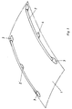
- Fig. 1 the roof 1 of a vehicle, not shown, is indicated by dash-dotted lines.
- two rails are fastened in the area of a longitudinal edge of the roof surface.
- the formation of each railing results from the exploded view according to FIG. 2, in which the individual parts are clearly shown.
- the roof railing consists of a railing tube 2 which is supported by at least two support feet 3 arranged at the two end regions thereof.
- the arrangement of three longer railing tubes 2 is recommended a third support leg 4 in the middle of the railing pipe.
- the railing tube 2 preferably consists of an extruded aluminum profile with a tube wall thickness that meets the technical requirements.
- Each support leg 3, 4 is formed in two parts and each consists of an adapter 5 made of metal and a cladding body 6 made of plastic that can be clipped onto it.
- Each adapter 5, which is preferably designed as a die-cast zinc part, is composed of a mounting plate 7 which rests on the vehicle roof 1 and a support body 8 which is integral therewith and strives vertically upward.
- the mounting plate 7 two bores 9 are provided for carrying out fastening means 90 with which the adapters 5 are to be fixed on the vehicle roof.
- Another bore 10 extends through the mounting plates 7 and support body 8.
- Cylinder screws 11 are passed through the bores 10 of the outer support feet 3, each of which penetrates a bore in the rail tube end regions and is screwed into a threaded plate 12 arranged in the rail tube 2.
- a thread-forming screw (DIN 7500) 13 extends through the bore 10 of the central support leg 4 and also penetrates a corresponding bore in the central region of the railing tube 2.
- the support body 8 are arranged asymmetrically on the mounting plates 7, such that the adapter 5 can be used on a cover.
- the adapter 5 of the support foot located at the front left in FIG. 1 corresponds to the support foot located at the rear on the right, as also applies to the front right and rear left. It is of course also conceivable to arrange the support bodies 8 symmetrically on the center of the fastening plates 7, but this would make the formation and assembly of the cladding bodies 6 more difficult.
- the casing bodies 6 each have a cap shape with molded-on clip designs 14, which can cooperate with undercuts, grooves or the like. Snap-in designs 15 on the support bodies 8 and, if appropriate, on the fastening plates 7, so that the casing bodies 6 can be mounted by simply plugging them on.
- documents 16 made of soft elastic material are attached, which are intended to prevent scratching of the vehicle paint as well as penetration of moisture into the screwing areas between the support legs 3, 4 and the vehicle roof .
- the new roof rails have an elegant appearance because e.g. the railing tube 2 can be anodized and the cladding body 6 can be painted and aerodynamically designed, whereby customer requirements can be met within wide limits with regard to the choice of colors and shape. Furthermore, the new roof railing consists of only a few, easy to connect individual parts and has a low weight. The installation of the new roof rails on the vehicle roof 1 does not require any special expertise and can be carried out from above under visual control. After the clip-on cladding body 6 has been clipped on, all of the fastening points are hidden from viewers, so that the new roof rails also meet the aesthetic demands of the buyers.
Landscapes
- Engineering & Computer Science (AREA)
- Mechanical Engineering (AREA)
- Body Structure For Vehicles (AREA)
- Fittings On The Vehicle Exterior For Carrying Loads, And Devices For Holding Or Mounting Articles (AREA)
Applications Claiming Priority (2)
| Application Number | Priority Date | Filing Date | Title |
|---|---|---|---|
| DE4323098A DE4323098A1 (de) | 1993-07-10 | 1993-07-10 | Dachreling für Fahrzeuge |
| DE4323098 | 1993-07-10 |
Publications (2)
| Publication Number | Publication Date |
|---|---|
| EP0633166A1 true EP0633166A1 (fr) | 1995-01-11 |
| EP0633166B1 EP0633166B1 (fr) | 1997-01-02 |
Family
ID=6492471
Family Applications (1)
| Application Number | Title | Priority Date | Filing Date |
|---|---|---|---|
| EP94109938A Expired - Lifetime EP0633166B1 (fr) | 1993-07-10 | 1994-06-28 | Rails de toit pour véhicules |
Country Status (5)
| Country | Link |
|---|---|
| US (1) | US5497925A (fr) |
| EP (1) | EP0633166B1 (fr) |
| JP (1) | JPH0769138A (fr) |
| DE (2) | DE4323098A1 (fr) |
| ES (1) | ES2096976T3 (fr) |
Cited By (1)
| Publication number | Priority date | Publication date | Assignee | Title |
|---|---|---|---|---|
| EP0689965A1 (fr) * | 1994-06-29 | 1996-01-03 | Happich Fahrzeug-Dachsysteme GmbH | Rails de toit pour véhicules |
Families Citing this family (29)
| Publication number | Priority date | Publication date | Assignee | Title |
|---|---|---|---|---|
| DE19534044A1 (de) * | 1995-09-14 | 1997-03-20 | Happich Fahrzeug Dachsysteme | Stützfuß für eine Fahrzeugdachreling |
| US5699944A (en) * | 1996-07-25 | 1997-12-23 | Avibank Mfg., Inc. | Vehicle roof rack assembly |
| USD415994S (en) | 1996-09-25 | 1999-11-02 | Marvin Behar | Portion of a carrying rack for positioning on top of an automobile |
| DE19649758A1 (de) * | 1996-11-30 | 1998-06-04 | Oris Fahrzeugteile Riehle H | Dachrelingsystem für Kraftfahrzeuge |
| US6037711A (en) * | 1997-01-10 | 2000-03-14 | Micron Technology, Inc. | Flat panel display anode that reduces the reflectance of ambient light |
| DE19716047C2 (de) * | 1997-04-17 | 1999-11-25 | Porsche Ag | Befestigungsvorrichtung für Dachlastträger |
| US6415970B1 (en) * | 2000-10-20 | 2002-07-09 | Jac Products, Inc. | Vehicle article carrier with supports configurable elevated siderails or flush mounted slats |
| US7204396B1 (en) * | 2002-07-18 | 2007-04-17 | Sportrack Automotive | One-piece support with integrated rail attachment mechanism and interchangeable outer cover |
| DE10314680B4 (de) * | 2003-04-01 | 2006-04-06 | Daimlerchrysler Ag | Dachgepäckträger |
| DE10346170A1 (de) * | 2003-10-01 | 2005-06-02 | Hagus C. Luchtenberg Gmbh & Co Kg | Fahrzeug-Dachreling |
| DE102006005541A1 (de) * | 2006-02-07 | 2007-08-16 | Hans und Ottmar Binder GmbH Oberflächenveredelung | Verfahren zur Oberflächenbearbeitung von Dachträgern für Kraftfahrzeuge sowie Dachträger für Kraftfahrzeuge |
| DE102006012050B4 (de) | 2006-03-16 | 2008-06-26 | Hans und Ottmar Binder GmbH Oberflächenveredelung | Dachreling für ein Kraftfahrzeug sowie Verfahren zur Herstellung einer Dachreling |
| SE529783C2 (sv) * | 2006-12-18 | 2007-11-20 | Thule Sweden Ab | Fästorgan för lasthållare vid fordon |
| JP4547419B2 (ja) * | 2007-12-11 | 2010-09-22 | 株式会社ファルテック | ルーフレールの取付構造 |
| DE102008004967A1 (de) * | 2008-01-11 | 2009-08-06 | Hans und Ottmar Binder GmbH Oberflächenveredelung | Tiefziehkappe für Dachreling |
| WO2009158728A1 (fr) * | 2008-06-27 | 2009-12-30 | Yakima Products, Inc. | Dispositifs de liaison pour relier des éléments de support de galerie de véhicule à des véhicules |
| CN101856996B (zh) * | 2010-06-21 | 2012-06-06 | 宁波信泰机械有限公司 | 一种汽车车顶行李架 |
| EP2716500B1 (fr) * | 2012-10-04 | 2016-12-07 | Dura Operating, LLC | Longeron de toit avec système de fixation |
| US9352696B2 (en) | 2013-11-11 | 2016-05-31 | Honda Motor Co., Ltd. | Low profile roof rail |
| US9718410B2 (en) * | 2015-02-05 | 2017-08-01 | Rhino Rack Australia Pty Limited | Assembly for connecting a roof rack to a vehicle |
| US20160272123A1 (en) * | 2015-03-20 | 2016-09-22 | GM Global Technology Operations LLC | Luggage carrier cross rail docking stations |
| US10005403B2 (en) * | 2015-10-30 | 2018-06-26 | Teraflex, Inc. | Roof rack system |
| EP3415370B1 (fr) * | 2017-06-12 | 2020-01-15 | Thule Sweden AB | Support de charge |
| US11878657B1 (en) * | 2019-06-13 | 2024-01-23 | Richard B. Pauli | Devices and methods to store and transport articles |
| US11752945B2 (en) * | 2020-02-06 | 2023-09-12 | Honda Motor Co., Ltd. | Roof rack system for a vehicle |
| DE102020133147B4 (de) * | 2020-12-11 | 2025-04-30 | FYSAM Auto Decorative GmbH | Dachreling für ein Kraftfahrzeug, Kraftfahrzeug sowie Verfahren zum Montieren einer Dachreling an einem Dach eines Kraftfahrzeugs |
| US11912240B2 (en) * | 2021-11-04 | 2024-02-27 | Jac Products, Inc. | Vehicle article carrier rack system with stowable, concealable cross bars |
| US12263815B2 (en) | 2022-08-25 | 2025-04-01 | Richard B. Pauli | Devices and methods to load and transport articles |
| JP2024107705A (ja) * | 2023-01-30 | 2024-08-09 | 株式会社Subaru | 車両用ルーフレール構造 |
Citations (4)
| Publication number | Priority date | Publication date | Assignee | Title |
|---|---|---|---|---|
| DE8136803U1 (de) * | 1981-12-17 | 1982-04-01 | Hagus C. Luchtenberg Gmbh & Co Kg, 5650 Solingen | Autodach |
| US4673119A (en) * | 1985-03-04 | 1987-06-16 | Bott John Anthony | Vehicle luggage carrier |
| FR2648093A1 (fr) * | 1989-06-07 | 1990-12-14 | Huron St Clair Inc | Support pour galerie de vehicule |
| US5069377A (en) * | 1990-12-10 | 1991-12-03 | Alton Baughman | Roof rack for vehicles |
Family Cites Families (11)
| Publication number | Priority date | Publication date | Assignee | Title |
|---|---|---|---|---|
| US3724730A (en) * | 1971-06-23 | 1973-04-03 | Jacobs Co | Car top luggage carrier |
| US4162755A (en) * | 1977-10-27 | 1979-07-31 | Bott John Anthony | Luggage carrier assembly |
| US4279368A (en) * | 1979-03-09 | 1981-07-21 | Four Star Corporation | Stanchion assembly |
| US4277009A (en) * | 1979-05-15 | 1981-07-07 | Bott John Anthony | Permanent luggage carrier adapters with removable primary luggage carriers |
| US4299346A (en) * | 1979-10-04 | 1981-11-10 | Auto Trends, Inc. | Automobile luggage rack |
| US4341332A (en) * | 1980-12-29 | 1982-07-27 | Four Star Corporation | Stanchion assembly |
| DE3539449A1 (de) * | 1985-11-07 | 1987-05-21 | Erbsloeh Julius & August | Verbindung von leichtmetallprofilen mit anschlusselementen |
| DE3720403A1 (de) * | 1987-06-19 | 1988-12-29 | Eugen Sommer | Dachgepaecktraeger fuer fahrzeuge |
| US5016799A (en) * | 1988-06-07 | 1991-05-21 | Huron/St. Clair Incorporated | Support stanchion for luggage carrier |
| DE4004829A1 (de) * | 1990-02-16 | 1991-08-22 | Happich Gmbh Gebr | Dachreling fuer fahrzeuge |
| US5253792A (en) * | 1991-07-11 | 1993-10-19 | Huron/St. Clair Incorporated | Luggage carrier with pop-up frame |
-
1993
- 1993-07-10 DE DE4323098A patent/DE4323098A1/de not_active Withdrawn
-
1994
- 1994-06-15 US US08/259,893 patent/US5497925A/en not_active Expired - Fee Related
- 1994-06-28 EP EP94109938A patent/EP0633166B1/fr not_active Expired - Lifetime
- 1994-06-28 ES ES94109938T patent/ES2096976T3/es not_active Expired - Lifetime
- 1994-06-28 DE DE59401451T patent/DE59401451D1/de not_active Expired - Fee Related
- 1994-07-08 JP JP6157534A patent/JPH0769138A/ja active Pending
Patent Citations (4)
| Publication number | Priority date | Publication date | Assignee | Title |
|---|---|---|---|---|
| DE8136803U1 (de) * | 1981-12-17 | 1982-04-01 | Hagus C. Luchtenberg Gmbh & Co Kg, 5650 Solingen | Autodach |
| US4673119A (en) * | 1985-03-04 | 1987-06-16 | Bott John Anthony | Vehicle luggage carrier |
| FR2648093A1 (fr) * | 1989-06-07 | 1990-12-14 | Huron St Clair Inc | Support pour galerie de vehicule |
| US5069377A (en) * | 1990-12-10 | 1991-12-03 | Alton Baughman | Roof rack for vehicles |
Cited By (1)
| Publication number | Priority date | Publication date | Assignee | Title |
|---|---|---|---|---|
| EP0689965A1 (fr) * | 1994-06-29 | 1996-01-03 | Happich Fahrzeug-Dachsysteme GmbH | Rails de toit pour véhicules |
Also Published As
| Publication number | Publication date |
|---|---|
| US5497925A (en) | 1996-03-12 |
| ES2096976T3 (es) | 1997-03-16 |
| JPH0769138A (ja) | 1995-03-14 |
| EP0633166B1 (fr) | 1997-01-02 |
| DE59401451D1 (de) | 1997-02-13 |
| DE4323098A1 (de) | 1995-01-12 |
Similar Documents
| Publication | Publication Date | Title |
|---|---|---|
| EP0633166B1 (fr) | Rails de toit pour véhicules | |
| DE4004829C2 (fr) | ||
| EP0657324B1 (fr) | Rails de toit pour véhicules | |
| EP0645282B1 (fr) | Pied de support de l'extrémité d'un profilé de galerie sur un toit de véhicule | |
| EP0689965B1 (fr) | Rails de toit pour véhicules | |
| DE10218873A1 (de) | Lasche | |
| DE202011001621U1 (de) | Vorrichtung zum Befestigen einer Träger- oder Zierleiste | |
| DE10221943A1 (de) | Dachträgersystem für ein Fahrzeug sowie Verfahren zur Herstellung des Dachträgersystems und Fahrzeug mit einem Dachträgersystem | |
| EP2425066B1 (fr) | Cloisonnement pour aménagement intérieur | |
| EP0806321A2 (fr) | Rails de toit pour véhicules | |
| EP1036707A2 (fr) | Rail de toit pour véhicules | |
| DE9415843U1 (de) | Verkleidungssystem für Bade- und Duschwannen | |
| DE9000484U1 (de) | Schublade mit Aufsatzrahmen | |
| EP1038489B1 (fr) | Installation de douches | |
| DE10313029B3 (de) | Höhenverstellbare Duschkabine oder Duschwand | |
| AT403651B (de) | Bordträger zur auflage von plattenförmigen elementen | |
| DE8801478U1 (de) | Windabweiser | |
| EP0786226B1 (fr) | Paroi de séparation de douche avec cloisons coulissantes ou articulées | |
| DE4442029A1 (de) | Spindeltreppe | |
| WO1991011939A1 (fr) | Bloc de support pour console | |
| DE29906836U1 (de) | Befestigungsanordnung für einen Handlauf | |
| DE20217578U1 (de) | Vordach, insbesondere Haustürvordach | |
| DE3629317C2 (fr) | ||
| DE102005019497A1 (de) | Füllelement für ein Geländer und Geländer dazu | |
| DE2726024A1 (de) | Klemm- und verstellbeschlag, insbesondere zum verstellbaren befestigen von vorhangschienen |
Legal Events
| Date | Code | Title | Description |
|---|---|---|---|
| PUAI | Public reference made under article 153(3) epc to a published international application that has entered the european phase |
Free format text: ORIGINAL CODE: 0009012 |
|
| AK | Designated contracting states |
Kind code of ref document: A1 Designated state(s): DE ES FR GB IT SE |
|
| 17P | Request for examination filed |
Effective date: 19950208 |
|
| 17Q | First examination report despatched |
Effective date: 19951212 |
|
| GRAG | Despatch of communication of intention to grant |
Free format text: ORIGINAL CODE: EPIDOS AGRA |
|
| GRAH | Despatch of communication of intention to grant a patent |
Free format text: ORIGINAL CODE: EPIDOS IGRA |
|
| GRAH | Despatch of communication of intention to grant a patent |
Free format text: ORIGINAL CODE: EPIDOS IGRA |
|
| GRAA | (expected) grant |
Free format text: ORIGINAL CODE: 0009210 |
|
| AK | Designated contracting states |
Kind code of ref document: B1 Designated state(s): DE ES FR GB IT SE |
|
| GBT | Gb: translation of ep patent filed (gb section 77(6)(a)/1977) |
Effective date: 19970102 |
|
| ITF | It: translation for a ep patent filed | ||
| ET | Fr: translation filed | ||
| REF | Corresponds to: |
Ref document number: 59401451 Country of ref document: DE Date of ref document: 19970213 |
|
| REG | Reference to a national code |
Ref country code: ES Ref legal event code: FG2A Ref document number: 2096976 Country of ref document: ES Kind code of ref document: T3 |
|
| PLBE | No opposition filed within time limit |
Free format text: ORIGINAL CODE: 0009261 |
|
| STAA | Information on the status of an ep patent application or granted ep patent |
Free format text: STATUS: NO OPPOSITION FILED WITHIN TIME LIMIT |
|
| 26N | No opposition filed | ||
| REG | Reference to a national code |
Ref country code: FR Ref legal event code: CD |
|
| PGFP | Annual fee paid to national office [announced via postgrant information from national office to epo] |
Ref country code: FR Payment date: 19990506 Year of fee payment: 6 |
|
| PGFP | Annual fee paid to national office [announced via postgrant information from national office to epo] |
Ref country code: SE Payment date: 19990517 Year of fee payment: 6 Ref country code: GB Payment date: 19990517 Year of fee payment: 6 |
|
| PGFP | Annual fee paid to national office [announced via postgrant information from national office to epo] |
Ref country code: ES Payment date: 19990604 Year of fee payment: 6 |
|
| PGFP | Annual fee paid to national office [announced via postgrant information from national office to epo] |
Ref country code: DE Payment date: 19990618 Year of fee payment: 6 |
|
| REG | Reference to a national code |
Ref country code: ES Ref legal event code: PC2A |
|
| PG25 | Lapsed in a contracting state [announced via postgrant information from national office to epo] |
Ref country code: GB Free format text: LAPSE BECAUSE OF NON-PAYMENT OF DUE FEES Effective date: 20000628 |
|
| PG25 | Lapsed in a contracting state [announced via postgrant information from national office to epo] |
Ref country code: SE Free format text: LAPSE BECAUSE OF NON-PAYMENT OF DUE FEES Effective date: 20000629 Ref country code: ES Free format text: THE PATENT HAS BEEN ANNULLED BY A DECISION OF A NATIONAL AUTHORITY Effective date: 20000629 |
|
| GBPC | Gb: european patent ceased through non-payment of renewal fee |
Effective date: 20000628 |
|
| EUG | Se: european patent has lapsed |
Ref document number: 94109938.4 |
|
| PG25 | Lapsed in a contracting state [announced via postgrant information from national office to epo] |
Ref country code: FR Free format text: LAPSE BECAUSE OF NON-PAYMENT OF DUE FEES Effective date: 20010228 |
|
| REG | Reference to a national code |
Ref country code: FR Ref legal event code: ST |
|
| PG25 | Lapsed in a contracting state [announced via postgrant information from national office to epo] |
Ref country code: DE Free format text: LAPSE BECAUSE OF NON-PAYMENT OF DUE FEES Effective date: 20010403 |
|
| REG | Reference to a national code |
Ref country code: ES Ref legal event code: FD2A Effective date: 20020304 |
|
| PG25 | Lapsed in a contracting state [announced via postgrant information from national office to epo] |
Ref country code: IT Free format text: LAPSE BECAUSE OF NON-PAYMENT OF DUE FEES;WARNING: LAPSES OF ITALIAN PATENTS WITH EFFECTIVE DATE BEFORE 2007 MAY HAVE OCCURRED AT ANY TIME BEFORE 2007. THE CORRECT EFFECTIVE DATE MAY BE DIFFERENT FROM THE ONE RECORDED. Effective date: 20050628 |