EP0806321A2 - Rails de toit pour véhicules - Google Patents
Rails de toit pour véhicules Download PDFInfo
- Publication number
- EP0806321A2 EP0806321A2 EP97102180A EP97102180A EP0806321A2 EP 0806321 A2 EP0806321 A2 EP 0806321A2 EP 97102180 A EP97102180 A EP 97102180A EP 97102180 A EP97102180 A EP 97102180A EP 0806321 A2 EP0806321 A2 EP 0806321A2
- Authority
- EP
- European Patent Office
- Prior art keywords
- adapter
- gallery
- roof
- rod
- roof rails
- Prior art date
- Legal status (The legal status is an assumption and is not a legal conclusion. Google has not performed a legal analysis and makes no representation as to the accuracy of the status listed.)
- Withdrawn
Links
- 229910052751 metal Inorganic materials 0.000 claims description 8
- 239000002184 metal Substances 0.000 claims description 8
- 210000002105 tongue Anatomy 0.000 claims description 6
- HCHKCACWOHOZIP-UHFFFAOYSA-N Zinc Chemical compound [Zn] HCHKCACWOHOZIP-UHFFFAOYSA-N 0.000 claims description 2
- 239000000463 material Substances 0.000 claims description 2
- 229910052725 zinc Inorganic materials 0.000 claims description 2
- 239000011701 zinc Substances 0.000 claims description 2
- 230000000149 penetrating effect Effects 0.000 abstract 1
- 230000015572 biosynthetic process Effects 0.000 description 3
- 238000006073 displacement reaction Methods 0.000 description 2
- 229910000838 Al alloy Inorganic materials 0.000 description 1
- 229910052782 aluminium Inorganic materials 0.000 description 1
- XAGFODPZIPBFFR-UHFFFAOYSA-N aluminium Chemical compound [Al] XAGFODPZIPBFFR-UHFFFAOYSA-N 0.000 description 1
- 238000011161 development Methods 0.000 description 1
- 230000018109 developmental process Effects 0.000 description 1
- 230000000694 effects Effects 0.000 description 1
- 239000004744 fabric Substances 0.000 description 1
- 239000011152 fibreglass Substances 0.000 description 1
- 238000004519 manufacturing process Methods 0.000 description 1
- 238000003801 milling Methods 0.000 description 1
- 238000000465 moulding Methods 0.000 description 1
- 230000003287 optical effect Effects 0.000 description 1
- 230000001737 promoting effect Effects 0.000 description 1
- 238000004080 punching Methods 0.000 description 1
- 230000001502 supplementing effect Effects 0.000 description 1
Images

Classifications
-
- B—PERFORMING OPERATIONS; TRANSPORTING
- B60—VEHICLES IN GENERAL
- B60R—VEHICLES, VEHICLE FITTINGS, OR VEHICLE PARTS, NOT OTHERWISE PROVIDED FOR
- B60R9/00—Supplementary fittings on vehicle exterior for carrying loads, e.g. luggage, sports gear or the like
- B60R9/04—Carriers associated with vehicle roof
Definitions
- the invention relates to a roof rail for vehicles with a gallery rod, the gallery rod receiving the end regions, enabling an arrangement of the gallery rod at a distance from the roof surface of a vehicle roof, which enables support elements and fastening means for fixing the support elements on a vehicle roof.
- roof rack systems For the transport of loads, it is known to arrange roof rack systems of various types on the roof of a vehicle. Roof rails with gallery bars and roof strips spaced from the roof surface, which rest directly on the vehicle roof, have essentially become established. There are advocates and buyers for both types of system, which makes it necessary for vehicle manufacturers to equip their vehicles with roof rails or roof strips, depending on the customer's requirements. Of course, this means increased warehousing and increased costs, which ultimately have to be borne by the end customers.
- the invention is therefore based on the object to provide a roof railing of the type mentioned, the optical and in particular technical aspects of the design and formation of a roof rail in corresponds essentially to the design and formation of a roof track in order to save one type of system and still be able to meet customer requirements.
- the gallery rod has a longitudinally running, upwardly open groove, that the groove is C-shaped, that each support element is designed as an adapter of relatively low design, that the adapter has a first axial portion for supporting a Gallery end and a second axial portion for mounting a cover cap and that the adapter has a hole passing through it for a fastener.
- roof rails according to the invention are suitable for mutually promoting and supplementing one another. Due to the fact that the gallery bar has a longitudinally running groove that is open at the top, the gallery bar remains such, but compared to the known models with the essential difference that it corresponds in function and appearance to a roof molding at the same time. From a functional point of view, the C-shaped groove is used to hold cross bars and their accessories.
- Each support element designed as an adapter is intended to replace the complex support feet which are otherwise customary in roof rails and, in addition, to serve as a carrier for an end cap.
- the indication of the relatively low design is intended to express that the height of the adapter only has to be so large that the gallery rod can just extend a small distance over the vehicle roof, taking into account any roof curvature.
- the distance of the gallery bar to the vehicle roof should not lose the character of a roof rail.
- the adapter is divided into a first and a second axial partial area in order to obtain useful support and mounting of the gallery rod on the one hand and a sensible fastening receptacle for the cover cap on the other. It goes without saying that stability requirements on the adapter only have to be met in the support area of the gallery rod, so that the rest of the area can be designed in a simple and material-saving manner.
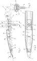
- the new roof railing consists of a gallery rod 1, a support element 2 on each gallery end, an end or cover cap 3 connected to each gallery end or each support element 2, and fastening elements, consisting of screws 4 provided with screw head 5.
- the new roof rail is made using the screws 4 attached to the vehicle roof 6 indicated by dash-dotted lines.
- the gallery rod 1 according to FIGS. 1 to 4 is designed as an extruded profile and consists, for. B. made of aluminum or an aluminum alloy.
- a first special feature of the gallery rod 1 is that it is formed with a longitudinally extending, upwardly open, C-shaped groove 7. The groove 7 is used for the arrangement and fastening of cross bars (not shown) or their accessories.
- a second special feature of the gallery rod 1 is that it also has a second, longitudinally running, downwardly open, C-shaped groove 8.
- the groove 8 is used for the arrangement of the support elements 2 which can be inserted therein.
- a third special feature of the gallery rod according to FIGS. 1 to 4 is the formation of longitudinally extending hollow chambers 9 which cooperate with the cover caps 3. The hollow chambers 9 save material and weight.
- Each gallery bar 1 consists of the cut section of a continuously manufactured Extruded profile.
- Each gallery stick 1 can be the same for any vehicle. The only differences are in the desired length of the gallery.
- the support element 2 according to FIGS. 1 to 4 is designed as an adapter 10 which is attached to a vehicle roof 6 by means of the screw 4, for. B. can be attached in that a weld nut (not shown) is arranged on a supporting body part under the roof skin.
- the adapter 10 is a forged part, a zinc die-cast part or possibly a glass fiber reinforced plastic injection-molded part. Since the adapter 10 is not visible in the installed state, no special requirements have to be made of its surface condition, so that the adapter 10 can be manufactured as a cheap mass-produced item.
- the adapter 10 has continuous grooves 11 on its longitudinal edges, which form an adapter head 12 and make it possible to insert the adapter 10 into an end region of the gallery rod 1, specifically into the lower groove 8 and with a first axial partial region 13.
- a second The axial section 14 of the adapter 10 serves to hold a cover flap 3 in place.
- the first axial section 13 of the adapter 10 is penetrated by a stepped bore 15 used to pass a screw 4.
- the gallery rod 1 also has through holes 16 for the screws 4 at its end regions.
- Each cap 3 can be made as a molded part, cast part or sheet metal part.
- Each cover cap 3 is formed with tongues 17 which project from one end and which, in the installed state, find a plug-in receptacle in the hollow chambers 9 of the gallery rod 1.
- each cover cap 3 has an inside pocket-shaped receptacle 18 for engaging the free adapter end, which is correspondingly tapered (FIG. 2).
- each cover cap 3 has in the central region a web 20 which is directed downward and engages in an opening 19 in the adapter 10. This design ensures reliable fixing of the cover caps 3.
- the cover caps 3 are expediently clipped onto the adapter 10, after which the adapter 10 is inserted into the gallery ends.
- the final assembly is carried out by screwing the screws 4 from above into the weld nuts mentioned. It is conceivable to design the screw heads 5 with a length that is sufficient to protrude into the through bores 16 in order to secure against displacement to effect for gallery staff 1. Of course, a security against displacement can also be realized by stops on the adapters 10.
- the gallery rod 1 is designed as a rolled profile, which u. U. is cheaper to manufacture than an extruded profile.
- this gallery rod 1 it is necessary for the assembly of the adapter 10 to form slot openings on the underside at the end regions, e.g. B. by milling or punching, of course, only on the condition that a connector, as described with reference to FIGS. 1 to 4 is desired.
- the adapter 10 is designed here as a shaped sheet-metal stamped part, which can be useful for cost reasons.
- the adapter 10 holds a screw 4 in which the screw head 5 is seated in a cage 21 which accommodates it in a displaceable and non-rotatable manner. This is formed from cut and raised sheet metal tabs 22 of the stamped sheet metal part.
- a fastening of the roof railing is provided from below, a threaded nut (not shown) being screwed onto the threaded shaft of the screw 4 from inside the vehicle.
Landscapes
- Engineering & Computer Science (AREA)
- Mechanical Engineering (AREA)
- Fittings On The Vehicle Exterior For Carrying Loads, And Devices For Holding Or Mounting Articles (AREA)
Applications Claiming Priority (2)
| Application Number | Priority Date | Filing Date | Title |
|---|---|---|---|
| DE19618641 | 1996-05-09 | ||
| DE1996118641 DE19618641A1 (de) | 1996-05-09 | 1996-05-09 | Dachreling für Fahrzeuge |
Publications (2)
| Publication Number | Publication Date |
|---|---|
| EP0806321A2 true EP0806321A2 (fr) | 1997-11-12 |
| EP0806321A3 EP0806321A3 (fr) | 1998-09-23 |
Family
ID=7793807
Family Applications (1)
| Application Number | Title | Priority Date | Filing Date |
|---|---|---|---|
| EP97102180A Withdrawn EP0806321A3 (fr) | 1996-05-09 | 1997-02-12 | Rails de toit pour véhicules |
Country Status (2)
| Country | Link |
|---|---|
| EP (1) | EP0806321A3 (fr) |
| DE (1) | DE19618641A1 (fr) |
Cited By (6)
| Publication number | Priority date | Publication date | Assignee | Title |
|---|---|---|---|---|
| WO2003033305A1 (fr) * | 2001-10-13 | 2003-04-24 | Thule Automotive Limited | Longeron de toit |
| EP1348597A1 (fr) * | 2002-03-25 | 2003-10-01 | Süddeutsche Aluminium Manufaktur GmbH | Porte-bagages de toit de véhicule |
| WO2006034304A1 (fr) * | 2004-09-21 | 2006-03-30 | Sportrack Llc | Ensemble de montant pour rail de toit de véhicule |
| WO2006111228A1 (fr) * | 2005-04-19 | 2006-10-26 | Hans und Ottmar Binder GmbH Oberflächenveredelung | Barre de toit destinee a un vehicule et procede de fixation de barre de toit |
| EP1985498A3 (fr) * | 2007-04-24 | 2011-05-11 | JAC Products Europe GmbH | Système de support d'une charge de toit |
| WO2022122972A1 (fr) * | 2020-12-11 | 2022-06-16 | FYSAM Auto Decorative GmbH | Galerie de toit pour un véhicule motorisé, véhicule motorisé et procédé de montage d'une galerie de toit sur un toit d'un véhicule motorisé |
Families Citing this family (1)
| Publication number | Priority date | Publication date | Assignee | Title |
|---|---|---|---|---|
| DE102005050196B4 (de) * | 2005-10-18 | 2016-05-04 | Jac Products Europe Gmbh | Dachreling auf einem Kraftfahrzeugdach |
Family Cites Families (6)
| Publication number | Priority date | Publication date | Assignee | Title |
|---|---|---|---|---|
| US4768691A (en) * | 1986-09-22 | 1988-09-06 | Huron/St. Clair Company, A Division Of Masco Industries, Inc. | Adjustable support rail for a luggage carrier |
| US5016799A (en) * | 1988-06-07 | 1991-05-21 | Huron/St. Clair Incorporated | Support stanchion for luggage carrier |
| US4911349A (en) * | 1989-07-03 | 1990-03-27 | Starboard Industries, Inc. | End cap with captive stud for article carriers |
| US5069377A (en) * | 1990-12-10 | 1991-12-03 | Alton Baughman | Roof rack for vehicles |
| DE4313526A1 (de) * | 1993-04-24 | 1994-10-27 | Happich Gmbh Gebr | Dachreling für Fahrzeuge |
| JP2877245B2 (ja) * | 1994-02-21 | 1999-03-31 | 理研精工株式会社 | 自動車用ルーフレール |
-
1996
- 1996-05-09 DE DE1996118641 patent/DE19618641A1/de not_active Withdrawn
-
1997
- 1997-02-12 EP EP97102180A patent/EP0806321A3/fr not_active Withdrawn
Cited By (8)
| Publication number | Priority date | Publication date | Assignee | Title |
|---|---|---|---|---|
| WO2003033305A1 (fr) * | 2001-10-13 | 2003-04-24 | Thule Automotive Limited | Longeron de toit |
| EP1348597A1 (fr) * | 2002-03-25 | 2003-10-01 | Süddeutsche Aluminium Manufaktur GmbH | Porte-bagages de toit de véhicule |
| WO2006034304A1 (fr) * | 2004-09-21 | 2006-03-30 | Sportrack Llc | Ensemble de montant pour rail de toit de véhicule |
| WO2006111228A1 (fr) * | 2005-04-19 | 2006-10-26 | Hans und Ottmar Binder GmbH Oberflächenveredelung | Barre de toit destinee a un vehicule et procede de fixation de barre de toit |
| US8720761B2 (en) | 2005-04-19 | 2014-05-13 | Hans Und Ottmar Binder Gmbh Oberflachenveredelung | Roof rack for a vehicle and method for fastening said roof rack |
| EP1985498A3 (fr) * | 2007-04-24 | 2011-05-11 | JAC Products Europe GmbH | Système de support d'une charge de toit |
| WO2022122972A1 (fr) * | 2020-12-11 | 2022-06-16 | FYSAM Auto Decorative GmbH | Galerie de toit pour un véhicule motorisé, véhicule motorisé et procédé de montage d'une galerie de toit sur un toit d'un véhicule motorisé |
| US12559039B2 (en) | 2020-12-11 | 2026-02-24 | FYSAM Auto Decorative GmbH | Roof rail for a motor vehicle, motor vehicle and method for mounting a roof rail on a roof of a motor vehicle |
Also Published As
| Publication number | Publication date |
|---|---|
| DE19618641A1 (de) | 1997-11-13 |
| EP0806321A3 (fr) | 1998-09-23 |
Similar Documents
| Publication | Publication Date | Title |
|---|---|---|
| EP1794031B1 (fr) | Systeme de galerie de toit pour vehicule, procede pour realiser le systeme de galerie de toit, et vehicule equipe d'un systeme de galerie de toit | |
| DE69014295T2 (de) | Geländerstabverbindung. | |
| EP0633166B1 (fr) | Rails de toit pour véhicules | |
| EP0657324B1 (fr) | Rails de toit pour véhicules | |
| EP0689965B1 (fr) | Rails de toit pour véhicules | |
| EP0645282A1 (fr) | Pied de support de l'extrémité d'un profilé de galerie sur un toit de véhicule | |
| DE7725760U1 (de) | Beschlag, insbesondere scharniertopf fuer moebelscharniere | |
| DE69003997T2 (de) | Leistungsverteilereinrichtung für Elektroinstallationen. | |
| DE69518478T2 (de) | Lastenträger, insbesondere Dachgepäckträger für Kraftfahrzeuge | |
| EP0806321A2 (fr) | Rails de toit pour véhicules | |
| DE19648330B4 (de) | Kraftfahrzeugkarosserie | |
| DE4018178C2 (de) | Tragstütze für Gepäckträger | |
| DE3820334C1 (en) | Arrangement for mounting a sun visor in a vehicle | |
| EP0897817B1 (fr) | Pare-soleil pour véhicules | |
| DE3301413C2 (de) | Vorrichtung zur Befestigung eines Dachgepäckträgers , Skihalters od. dgl. auf einem Fahrzeugdach | |
| DE102020133147A1 (de) | Dachreling für ein Kraftfahrzeug, Kraftfahrzeug sowie Verfahren zum Montieren einer Dachreling an einem Dach eines Kraftfahrzeugs | |
| EP0837254A1 (fr) | Dispositif d'ancrage pour paroi creuse | |
| EP0805068B1 (fr) | Rails de toit pour véhicules | |
| DE4418528C1 (de) | Dachreling für Fahrzeuge | |
| WO2021058109A1 (fr) | Ensemble détachable de fixation de porte-bagages de toit sur le toit d'un véhicule à moteur | |
| EP0845391B1 (fr) | Rails de toit pour véhicules. | |
| EP0694666B1 (fr) | Porte ou fenêtre avec éléments de verrouillage | |
| DE4413957A1 (de) | Dachlastenträgeranordnung für Fahrzeuge | |
| DE3607744C2 (fr) | ||
| DE10029544A1 (de) | Befestigungselement |
Legal Events
| Date | Code | Title | Description |
|---|---|---|---|
| PUAI | Public reference made under article 153(3) epc to a published international application that has entered the european phase |
Free format text: ORIGINAL CODE: 0009012 |
|
| 17P | Request for examination filed |
Effective date: 19970221 |
|
| AK | Designated contracting states |
Kind code of ref document: A2 Designated state(s): DE FR GB SE |
|
| PUAL | Search report despatched |
Free format text: ORIGINAL CODE: 0009013 |
|
| AK | Designated contracting states |
Kind code of ref document: A3 Designated state(s): DE FR GB SE |
|
| RAP1 | Party data changed (applicant data changed or rights of an application transferred) |
Owner name: JAC PRODUCTS DEUTSCHLAND GMBH |
|
| 17Q | First examination report despatched |
Effective date: 20000215 |
|
| GRAG | Despatch of communication of intention to grant |
Free format text: ORIGINAL CODE: EPIDOS AGRA |
|
| STAA | Information on the status of an ep patent application or granted ep patent |
Free format text: STATUS: THE APPLICATION HAS BEEN WITHDRAWN |
|
| 18W | Application withdrawn |
Withdrawal date: 20001122 |