EP0633362B1 - Schachtabdeckung mit Abdichtung - Google Patents
Schachtabdeckung mit Abdichtung Download PDFInfo
- Publication number
- EP0633362B1 EP0633362B1 EP94201666A EP94201666A EP0633362B1 EP 0633362 B1 EP0633362 B1 EP 0633362B1 EP 94201666 A EP94201666 A EP 94201666A EP 94201666 A EP94201666 A EP 94201666A EP 0633362 B1 EP0633362 B1 EP 0633362B1
- Authority
- EP
- European Patent Office
- Prior art keywords
- cover means
- frame
- rib
- lid
- ducts
- Prior art date
- Legal status (The legal status is an assumption and is not a legal conclusion. Google has not performed a legal analysis and makes no representation as to the accuracy of the status listed.)
- Expired - Lifetime
Links
- 239000007788 liquid Substances 0.000 claims abstract description 23
- 238000007789 sealing Methods 0.000 claims abstract description 13
- 229920002994 synthetic fiber Polymers 0.000 claims description 4
- 239000003365 glass fiber Substances 0.000 claims description 2
- XLYOFNOQVPJJNP-UHFFFAOYSA-N water Substances O XLYOFNOQVPJJNP-UHFFFAOYSA-N 0.000 description 7
- 238000010276 construction Methods 0.000 description 2
- 230000004888 barrier function Effects 0.000 description 1
- 238000005452 bending Methods 0.000 description 1
- 230000007547 defect Effects 0.000 description 1
- 230000000694 effects Effects 0.000 description 1
- 239000000295 fuel oil Substances 0.000 description 1
- 230000035515 penetration Effects 0.000 description 1
- 230000000630 rising effect Effects 0.000 description 1
Images
Classifications
-
- E—FIXED CONSTRUCTIONS
- E02—HYDRAULIC ENGINEERING; FOUNDATIONS; SOIL SHIFTING
- E02D—FOUNDATIONS; EXCAVATIONS; EMBANKMENTS; UNDERGROUND OR UNDERWATER STRUCTURES
- E02D29/00—Independent underground or underwater structures; Retaining walls
- E02D29/12—Manhole shafts; Other inspection or access chambers; Accessories therefor
- E02D29/14—Covers for manholes or the like; Frames for covers
Definitions
- the present invention concerns a device for sealing pits, in particular a device which consists of a horizontal frame and cover means fitting in the frame, such as a lid.
- odour seals usually consist of grooves in the form of ducts which are provided in the above-mentioned frames and ribs on the bottom side of the lids which extend into the above-mentioned ducts, one and other such that when the ducts are filled with water, a barrier is formed for the odour rising from the pit.
- the pit lids can seal in a watertight manner. This is among other the case in control rooms which are situated above the lid of a tank, such as a fuel oil tank.
- a tank such as a fuel oil tank.
- various solutions have already been suggested, including the use of elastic sealing rings.
- the known devices for sealing pits whereby an odour seal and/or a seal to prevent the penetration of liquid, such as rain water, is provided (see EP-A-0 390 767), are all disadvantageous in that they no longer meet the above-mentioned requirements after some time, especially when the pit lids used hereby are heavily loaded, for example by vehicles driving over them. Many of the usual defects hereby arise as the pit lids bend and the seatings, where the lids rest in the frames, are damaged. This phenomenon particularly occurs with synthetic lids.
- the present invention aims a device for sealing pits which does not have the above-mentioned disadvantages, in other words whereby an optimum sealing is provided on the one hand, in order to prevent that odour escapes and/or that liquid seeps in the pit, and whereby damages to the seal arising under an extremely heavy load are optimally excluded on the other hand, even when the frames and lids are made of synthetic material and when the load is more than 12 tons.
- the invention concerns a device for sealing pits, consisting of a horizontal frame and cover means fitting in this frame, characterized in that the frame has two concentric ducts which can each contain an amount of liquid; in that the cover means have two ribs on their bottom sides which extend into the concentric ducts as the cover means are applied, whereby the ducts and ribs are made such that two liquid seals are created with an inclusion of air in between which prevents liquid from entering; in that the outer rib rests in the outer duct, preferably on the bottom thereof; in that the outer rib serves as a support for at least the part of the cover means which serves as bearing surface; and in that there are free spaces around the ribs in the ducts.
- the above-mentioned construction is advantageous in that the load which is exerted on the bearing surface of the cover means is optimally transferred to the frame, without certain ribs being bent in their seatings and breaking off.
- the above-mentioned cover means may hereby consist of a single lid which has at least two ribs on its bottom side which work in conjunction with the above-mentioned concentric ducts, or they may consist of two separate lids placed on top of one another, of which the top lid has a rib on its bottom side which works in conjunction with the outer duct and of which the bottom lid has a rib on its bottom side which works in conjunction with the inner duct.
- the device for sealing pits consists of a horizontal frame and cover means fitting in this frame, characterized in that the cover means consist of two lids placed on top of one another; in that the frame has two concentric ducts which can each contain an amount of liquid; in that the top lid has a rib on its bottom side which extends into the outer duct and in that the bottom lid has a rib on its bottom side which extends into the inner duct, such that an inclusion of air is created in between the lids which prevents liquid from entering; and in that there are free spaces around the rib of the top lid.
- the cover means consist of two lids placed on top of one another; in that the frame has two concentric ducts which can each contain an amount of liquid; in that the top lid has a rib on its bottom side which extends into the outer duct and in that the bottom lid has a rib on its bottom side which extends into the inner duct, such that an inclusion of air is created in between the lids which prevents liquid from entering; and in that there are free spaces around the
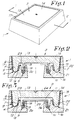
- the invention concerns a device 1 for sealing pits, consisting of a horizontal frame 2 and cover means 3 fitting in this frame.
- the device 1 is characterized in that the frame 2 has two concentric ducts 4 and 5 which can each contain an amount of liquid 6; in that the cover means 3 have two ribs 7 and 8 on their bottom sides which extend into the concentric ducts 4 and 5 as the cover means 3 are applied, whereby these ducts and ribs are made such that two liquid seals 9 and 10 are created with an inclusion of air 11 in between, which can prevent liquid 6 from entering in the pit; in that the outer rib 7 rests on the bottom 12 of the outer duct 4; and in that the outer rib 7 serves as a support for at least the part of the cover means 3 which serves as bearing surface 13.
- the cover means 3 consist of a single lid 14.
- the outer rib 7 is preferably situated on the inner edge 15 of the lid 14, such that this lid 14 cannot topple, not even under a very heavy load, and does cannot come out of the frame 2, for example when heavy vehicles drive over it.
- the base 16 of the frame 2 preferably extends under the outer rib 7, such that pressure forces are vertically transferred downward from the rib 7 to the construction provided under the frame 2, as a result of which the frame 2 is not under any strain of bending.
- the device 1 is preferably also provided with positioning means to position the lid 14, or at least the rib 7 in the frame 2, such that the lid 14, as the pit is sealed, always fits in the same place in the frame 2, and the above-mentioned spaces 17, 18, 19 and 20 are respected.
- these positioning means consist of a seating 21 for the bottom edge 22 of the rib 7.
- the second rib 8 hangs down entirely freely in the duct 5.
- the lid 13 is entirely countersunk in the frame 2.
- the frame 2 and the cover means 3, in this case the lid 14, are made of synthetic material, which may be reinforced with glass fibres.
- the device 1 according to the invention is advantageous in that water cannot seep in the underlying pit.
- a liquid for example rain water
- enters the space 17 it will seep through into the space 18.
- the water from the space 18 will run over the wall 23 between the ducts 4 and 5 into the duct 5.
- an inclusion of air 11 is created.
- a counterpressure is created which finally results in a situation as represented in figure 2 whereby the water column in the space 20 is higher than in the space 19.
- the pressure which is thus created in the inclusion of air 11 prevents the liquid from flowing any further from the duct 4 into the duct 5, even when the space 17 is entirely filled with liquid.
- the ducts 4 and 5 should hereby be suitably dimensioned, whereby the minimum dimensions can be either calculated or determined by experiment.
- Figure 3 shows a variant whereby the cover means 3 consist of two lids 24 and 25 situated on top of one another.
- the above-mentioned rib 7 is hereby part of the lid 24 and the above-mentioned rib 8 is part of the lid 25.
- the lid 25 rest on the inner edge 26 of the frame 2, and there is an air slot between the two lids.
- the embodiment of figure 3 is also advantageous in that the space of the inclusion of air 11 is bigger than in the embodiment of figure 2 and in that a downward pressure force is exerted on the lid 25, as a result of which it is pressed onto the inner edge 26.
- Another advantage of the embodiment of figure 3 consists in that the liquid 6, as an underpressure is created in the pit, is not sucked inside, as in this case the lid 25 is sucked onto the inner edge 26 and the suction of the liquid 6 is prevented.
- the invention also concerns a device 1 which is provided, as represented in figure 3, with two lids 24 and 25, whereby the top lid 24 has a rib 7 which fits in the duct 4, and the bottom lid 25 has a rib 8 which fits in the duct 6, regardless of whether the rib 7 serves as a support or not.
- cover means 3 consist of two lids 24 and 25 instead of one single lid 14, all characteristics which are described by means of figure 2 are also valid for the embodiment of figure 3.
Landscapes
- Engineering & Computer Science (AREA)
- Civil Engineering (AREA)
- Life Sciences & Earth Sciences (AREA)
- General Life Sciences & Earth Sciences (AREA)
- Mining & Mineral Resources (AREA)
- Paleontology (AREA)
- Environmental & Geological Engineering (AREA)
- General Engineering & Computer Science (AREA)
- Structural Engineering (AREA)
- Pressure Vessels And Lids Thereof (AREA)
- Laying Of Electric Cables Or Lines Outside (AREA)
- Closures For Containers (AREA)
- Sealing Devices (AREA)
Claims (11)
- Vorrichtung zum Abdichten von Schächten, bestehend aus einem horizontalen Rahmen (2) und in diesen Rahmen (2) passenden Abdeckmitteln (3), dadurch gekennzeichnet, daß der Rahmen (2) zwei konzentrische Kanäle (4, 5) aufweist, die jeder eine Flüssigkeitsmenge (6) aufnehmen können; dadurch, daß die Abdeckmittel (3) an ihren Unterseiten zwei Rippen (7, 8) haben, die sich in die konzentrischen Kanäle (4, 5) erstrecken, wenn die Abdeckmittel (3) angebracht werden, wobei diese Kanäle und Rippen so ausgeführt sind, daß zwei Flüssigkeitsdichtungen (9, 10) mit dazwischen einem Lufteinschluß (11) gebildet werden, die das Eindringen von Flüssigkeit (6) in den Schacht verhindern können; dadurch, daß die äußere Rippe (7) im äußeren Kanal (4) aufliegt; dadurch, daß die äußere Rippe (7) als Stütze dient für zumindest den Teil der Abdeckmittel (3), der als tragende Fläche (13) dient; und dadurch, daß freie Räume (17, 18, 19, 20) um die Rippen (7, 8) in den Kanälen (4, 5) vorhanden sind.
- Vorrichtung gemäß Anspruch 1, dadurch gekennzeichnet, daß die äußere Rippe (7) auf dem Boden des äußeren Kanals (4) aufliegt.
- Vorrichtung gemäß Anspruch 1 oder 2, dadurch gekennzeichnet, daß die äußere Rippe (7) sich an der äußeren Kante (15) der Abdeckmittel (3) befindet.
- Vorrichtung gemäß einem der obigen Ansprüche, dadurch gekennzeichnet, daß sie mit Positioniermitteln versehen ist, die zumindest für das Positionieren der äußeren Rippe (7) im äußeren Kanal (8) sorgen, und die aus einem Sitz (21) für die Unterkante der obenerwähnten äußeren Rippe (7) bestehen.
- Vorrichtung gemäß einem der obigen Ansprüche, dadurch gekennzeichnet, daß die Basis (16) des Rahmens (2) sich bis unter die äußere Rippe (7) der Abdeckmittel (3) erstreckt.
- Vorrichtung gemäß einem der obigen Ansprüche, dadurch gekennzeichnet, daß die Abdeckmittel (3) aus einem einzigen Deckel (14) bestehen, an dessen Unterseite die beiden obenerwähnten Rippen (7, 8) angebracht sind.
- Vorrichtung gemäß einem der Ansprüche 1 bis 5, dadurch gekennzeichnet, daß die Abdeckmittel (3) aus zwei übereinander angeordneten Deckeln (24, 25) bestehen, wobei die äußere Rippe (7) sich am oberen Deckel (24) befindet und die innere Rippe (8) sich am unteren Deckel (25) befindet.
- Vorrichtung zum Abdichten von Schächten, bestehend aus einem horizontalen Rahmen (2) und in diesen Rahmen (2) passenden Abdeckmitteln (3), dadurch gekennzeichnet, daß die Abdeckmittel (3) aus zwei übereinander angeordneten Deckeln (24, 25) bestehen; dadurch, daß der Rahmen (2) zwei konzentrische Kanäle (4, 5) aufweist, die jeder eine Flüssigkeitsmenge (6) aufnehmen können; dadurch, daß der obere Deckel (24) eine Rippe (7) an seiner Unterseite hat, die sich in den äußeren Kanal (4) erstreckt, und daß der untere Deckel (24) an seiner Unterseite eine Rippe (8) aufweist, die sich in den inneren Kanal (5) erstreckt, so daß zwischen den Deckeln (24, 25) ein Lufteinschluß (11) erzeugt wird, der das Eindringen von Flüssigkeit (6) in den Schacht verhindert; und dadurch, daß freie Räume (17-18) um die Rippe (7) des oberen Deckels (24) vorhanden sind.
- Vorrichtung gemäß Anspruch 7 oder 8, dadurch gekennzeichnet, daß der untere Deckel (25) auf der Innenkante (26) des Rahmens (2) aufliegt, und dadurch, daß zwischen beiden Deckeln (24, 25) ein fortlaufender Luftspalt vorhanden ist.
- Vorrichtung gemäß einem der obigen Ansprüche, dadurch gekennzeichnet, daß sowohl der Rahmen (2) als auch die Abdeckmittel (3) aus Kunststoff gefertigt sind.
- Vorrichtung gemäß Anspruch 10, dadurch gekennzeichnet, daß der Kunststoff mit Glasfasern verstärkt ist.
Applications Claiming Priority (2)
| Application Number | Priority Date | Filing Date | Title |
|---|---|---|---|
| BE9300672A BE1007256A3 (nl) | 1993-06-30 | 1993-06-30 | Inrichting voor het afsluiten van putten. |
| BE9300672 | 1993-06-30 |
Publications (2)
| Publication Number | Publication Date |
|---|---|
| EP0633362A1 EP0633362A1 (de) | 1995-01-11 |
| EP0633362B1 true EP0633362B1 (de) | 1998-09-16 |
Family
ID=3887143
Family Applications (1)
| Application Number | Title | Priority Date | Filing Date |
|---|---|---|---|
| EP94201666A Expired - Lifetime EP0633362B1 (de) | 1993-06-30 | 1994-06-10 | Schachtabdeckung mit Abdichtung |
Country Status (4)
| Country | Link |
|---|---|
| EP (1) | EP0633362B1 (de) |
| AT (1) | ATE171233T1 (de) |
| BE (1) | BE1007256A3 (de) |
| DE (1) | DE69413324T2 (de) |
Families Citing this family (5)
| Publication number | Priority date | Publication date | Assignee | Title |
|---|---|---|---|---|
| ES1046740Y (es) * | 2000-07-24 | 2001-06-16 | Albemarna S L | Dispositivo de cierre para arqueta de registro. |
| DE102004039360A1 (de) | 2004-08-12 | 2006-02-23 | Georg Prinzing Gmbh & Co Kg Betonformen- Und Maschinenfabrik | Schachtsystem mit Transport- und Verschiebesicherung |
| FR2956418B1 (fr) * | 2010-02-18 | 2012-08-17 | Norinco | Regard de chaussee a cadre et tampon pourvu d'un joint d'amortissement et d'etancheite |
| GB2502949A (en) * | 2012-04-23 | 2013-12-18 | Wrekin Holdings Ltd | Drain cover and frame assembly |
| CN108193718A (zh) * | 2018-02-22 | 2018-06-22 | 中国恩菲工程技术有限公司 | 应用于抓斗检修洞口的密封组件 |
Family Cites Families (4)
| Publication number | Priority date | Publication date | Assignee | Title |
|---|---|---|---|---|
| GB2093509B (en) * | 1981-02-19 | 1984-11-07 | Clark Francis Sidney | An access cover and frame assembly |
| JPS59192135A (ja) * | 1983-04-14 | 1984-10-31 | Daikyo:Kk | 鋼矢板の防蝕化構造 |
| GB8324549D0 (en) * | 1983-09-14 | 1983-10-19 | Clarksteel Ltd | Access cover and frame assembly |
| BE1004360A3 (fr) * | 1989-03-31 | 1992-11-10 | Debergh Ludo | Dispositif de fermeture etanche pour regard. |
-
1993
- 1993-06-30 BE BE9300672A patent/BE1007256A3/nl not_active IP Right Cessation
-
1994
- 1994-06-10 EP EP94201666A patent/EP0633362B1/de not_active Expired - Lifetime
- 1994-06-10 AT AT94201666T patent/ATE171233T1/de not_active IP Right Cessation
- 1994-06-10 DE DE69413324T patent/DE69413324T2/de not_active Expired - Fee Related
Also Published As
| Publication number | Publication date |
|---|---|
| ATE171233T1 (de) | 1998-10-15 |
| DE69413324D1 (de) | 1998-10-22 |
| BE1007256A3 (nl) | 1995-05-02 |
| DE69413324T2 (de) | 1999-05-12 |
| EP0633362A1 (de) | 1995-01-11 |
Similar Documents
| Publication | Publication Date | Title |
|---|---|---|
| US5090713A (en) | Elastomeric gasket for sealing a glass fiber reinforced cover to a vault | |
| EP0633362B1 (de) | Schachtabdeckung mit Abdichtung | |
| US5401114A (en) | Manhole ventilation insert with duct shut-off device | |
| EP1603825B1 (de) | Automatische ventilanordnung für einen wasserkühlerspeicher | |
| CA2380756A1 (en) | Container lid including venting and denesting features | |
| DK164517B (da) | Daeksel og ramme til en gade- eller nedstigningsbroend | |
| EP0072026B1 (de) | Aufrollbares abdichtendes Schleusentor | |
| US4661047A (en) | Submersible pump guide rail arrangement | |
| KR20140027688A (ko) | 차수판 폐쇄장치 | |
| US5287986A (en) | Containment tank assembly | |
| GB2110749A (en) | Motor vehicle sliding roof with a combined edge seal and wind deflector | |
| CA2298230A1 (en) | Sealed top cover and lid for washing machine | |
| US4811859A (en) | Seal for floating roof | |
| JP2001220765A (ja) | 人孔蓋 | |
| WO2000046864A3 (en) | Low profile ventable seal for an electrochemical cell | |
| EP0464097B1 (de) | Kunststoffbehälter | |
| GB2185053A (en) | An access cover frame | |
| EP0155622A3 (en) | Vertically adjustable bearing for the transferring and raising and/or lowering of heavy loads, particularly of bridges | |
| US5687816A (en) | Underground storage space | |
| DK1013844T3 (da) | Vandaflöb | |
| EP1028219A3 (de) | Vorrichtung zum Abdichten einer Öffnung | |
| KR102056023B1 (ko) | 밀폐형 맨홀 뚜껑 | |
| US2497851A (en) | Lifter roof storage tank | |
| GB2299357A (en) | Access frame | |
| GB2245627A (en) | Manhole cover and frame assembly |
Legal Events
| Date | Code | Title | Description |
|---|---|---|---|
| PUAI | Public reference made under article 153(3) epc to a published international application that has entered the european phase |
Free format text: ORIGINAL CODE: 0009012 |
|
| AK | Designated contracting states |
Kind code of ref document: A1 Designated state(s): AT CH DE ES FR GB IT LI LU NL PT |
|
| 17P | Request for examination filed |
Effective date: 19950706 |
|
| 17Q | First examination report despatched |
Effective date: 19970314 |
|
| GRAG | Despatch of communication of intention to grant |
Free format text: ORIGINAL CODE: EPIDOS AGRA |
|
| GRAG | Despatch of communication of intention to grant |
Free format text: ORIGINAL CODE: EPIDOS AGRA |
|
| GRAH | Despatch of communication of intention to grant a patent |
Free format text: ORIGINAL CODE: EPIDOS IGRA |
|
| GRAH | Despatch of communication of intention to grant a patent |
Free format text: ORIGINAL CODE: EPIDOS IGRA |
|
| RIN1 | Information on inventor provided before grant (corrected) |
Inventor name: KRUYFHOOFT, CHRISTINA |
|
| GRAA | (expected) grant |
Free format text: ORIGINAL CODE: 0009210 |
|
| RAP1 | Party data changed (applicant data changed or rights of an application transferred) |
Owner name: ISOKING, N.V. |
|
| AK | Designated contracting states |
Kind code of ref document: B1 Designated state(s): AT CH DE ES FR GB IT LI LU NL PT |
|
| PG25 | Lapsed in a contracting state [announced via postgrant information from national office to epo] |
Ref country code: LI Free format text: LAPSE BECAUSE OF FAILURE TO SUBMIT A TRANSLATION OF THE DESCRIPTION OR TO PAY THE FEE WITHIN THE PRESCRIBED TIME-LIMIT Effective date: 19980916 Ref country code: IT Free format text: LAPSE BECAUSE OF FAILURE TO SUBMIT A TRANSLATION OF THE DESCRIPTION OR TO PAY THE FEE WITHIN THE PRE;WARNING: LAPSES OF ITALIAN PATENTS WITH EFFECTIVE DATE BEFORE 2007 MAY HAVE OCCURRED AT ANY TIME BEFORE 2007. THE CORRECT EFFECTIVE DATE MAY BE DIFFERENT FROM THE ONE RECORDED.SCRIBED TIME-LIMIT Effective date: 19980916 Ref country code: FR Free format text: LAPSE BECAUSE OF FAILURE TO SUBMIT A TRANSLATION OF THE DESCRIPTION OR TO PAY THE FEE WITHIN THE PRESCRIBED TIME-LIMIT Effective date: 19980916 Ref country code: ES Free format text: THE PATENT HAS BEEN ANNULLED BY A DECISION OF A NATIONAL AUTHORITY Effective date: 19980916 Ref country code: CH Free format text: LAPSE BECAUSE OF FAILURE TO SUBMIT A TRANSLATION OF THE DESCRIPTION OR TO PAY THE FEE WITHIN THE PRESCRIBED TIME-LIMIT Effective date: 19980916 Ref country code: AT Free format text: LAPSE BECAUSE OF FAILURE TO SUBMIT A TRANSLATION OF THE DESCRIPTION OR TO PAY THE FEE WITHIN THE PRESCRIBED TIME-LIMIT Effective date: 19980916 |
|
| REF | Corresponds to: |
Ref document number: 171233 Country of ref document: AT Date of ref document: 19981015 Kind code of ref document: T |
|
| REG | Reference to a national code |
Ref country code: CH Ref legal event code: EP |
|
| REF | Corresponds to: |
Ref document number: 69413324 Country of ref document: DE Date of ref document: 19981022 |
|
| PG25 | Lapsed in a contracting state [announced via postgrant information from national office to epo] |
Ref country code: PT Free format text: LAPSE BECAUSE OF FAILURE TO SUBMIT A TRANSLATION OF THE DESCRIPTION OR TO PAY THE FEE WITHIN THE PRESCRIBED TIME-LIMIT Effective date: 19981218 |
|
| EN | Fr: translation not filed | ||
| REG | Reference to a national code |
Ref country code: CH Ref legal event code: PL |
|
| PGFP | Annual fee paid to national office [announced via postgrant information from national office to epo] |
Ref country code: GB Payment date: 19990615 Year of fee payment: 6 |
|
| PGFP | Annual fee paid to national office [announced via postgrant information from national office to epo] |
Ref country code: LU Payment date: 19990625 Year of fee payment: 6 |
|
| PLBE | No opposition filed within time limit |
Free format text: ORIGINAL CODE: 0009261 |
|
| STAA | Information on the status of an ep patent application or granted ep patent |
Free format text: STATUS: NO OPPOSITION FILED WITHIN TIME LIMIT |
|
| 26N | No opposition filed | ||
| PG25 | Lapsed in a contracting state [announced via postgrant information from national office to epo] |
Ref country code: LU Free format text: LAPSE BECAUSE OF NON-PAYMENT OF DUE FEES Effective date: 20000610 Ref country code: GB Free format text: LAPSE BECAUSE OF NON-PAYMENT OF DUE FEES Effective date: 20000610 |
|
| GBPC | Gb: european patent ceased through non-payment of renewal fee |
Effective date: 20000610 |
|
| PGFP | Annual fee paid to national office [announced via postgrant information from national office to epo] |
Ref country code: NL Payment date: 20090630 Year of fee payment: 16 |
|
| PGFP | Annual fee paid to national office [announced via postgrant information from national office to epo] |
Ref country code: DE Payment date: 20090629 Year of fee payment: 16 |
|
| REG | Reference to a national code |
Ref country code: NL Ref legal event code: V1 Effective date: 20110101 |
|
| PG25 | Lapsed in a contracting state [announced via postgrant information from national office to epo] |
Ref country code: DE Free format text: LAPSE BECAUSE OF NON-PAYMENT OF DUE FEES Effective date: 20110101 |
|
| PG25 | Lapsed in a contracting state [announced via postgrant information from national office to epo] |
Ref country code: NL Free format text: LAPSE BECAUSE OF NON-PAYMENT OF DUE FEES Effective date: 20110101 |