EP0633372B1 - Türdrückeranordnung - Google Patents
Türdrückeranordnung Download PDFInfo
- Publication number
- EP0633372B1 EP0633372B1 EP94304729A EP94304729A EP0633372B1 EP 0633372 B1 EP0633372 B1 EP 0633372B1 EP 94304729 A EP94304729 A EP 94304729A EP 94304729 A EP94304729 A EP 94304729A EP 0633372 B1 EP0633372 B1 EP 0633372B1
- Authority
- EP
- European Patent Office
- Prior art keywords
- lever handle
- cam
- slider
- door
- lever
- Prior art date
- Legal status (The legal status is an assumption and is not a legal conclusion. Google has not performed a legal analysis and makes no representation as to the accuracy of the status listed.)
- Expired - Lifetime
Links
- 230000000903 blocking effect Effects 0.000 claims description 11
- 229920001971 elastomer Polymers 0.000 claims description 8
- 239000000806 elastomer Substances 0.000 claims description 8
- 230000006835 compression Effects 0.000 claims description 3
- 238000007906 compression Methods 0.000 claims description 3
- 230000003993 interaction Effects 0.000 description 3
- 230000036316 preload Effects 0.000 description 3
- 239000000463 material Substances 0.000 description 2
- 230000000712 assembly Effects 0.000 description 1
- 238000000429 assembly Methods 0.000 description 1
- 230000000694 effects Effects 0.000 description 1
- 239000002184 metal Substances 0.000 description 1
Images



Classifications
-
- E—FIXED CONSTRUCTIONS
- E05—LOCKS; KEYS; WINDOW OR DOOR FITTINGS; SAFES
- E05C—BOLTS OR FASTENING DEVICES FOR WINGS, SPECIALLY FOR DOORS OR WINDOWS
- E05C9/00—Arrangements of simultaneously actuated bolts or other securing devices at well-separated positions on the same wing
- E05C9/04—Arrangements of simultaneously actuated bolts or other securing devices at well-separated positions on the same wing with two sliding bars moved in opposite directions when fastening or unfastening
-
- E—FIXED CONSTRUCTIONS
- E05—LOCKS; KEYS; WINDOW OR DOOR FITTINGS; SAFES
- E05B—LOCKS; ACCESSORIES THEREFOR; HANDCUFFS
- E05B15/00—Other details of locks; Parts for engagement by bolts of fastening devices
- E05B15/004—Lost motion connections
-
- E—FIXED CONSTRUCTIONS
- E05—LOCKS; KEYS; WINDOW OR DOOR FITTINGS; SAFES
- E05B—LOCKS; ACCESSORIES THEREFOR; HANDCUFFS
- E05B17/00—Accessories in connection with locks
- E05B17/0054—Fraction or shear lines; Slip-clutches, resilient parts or the like for preventing damage when forced or slammed
- E05B17/0058—Fraction or shear lines; Slip-clutches, resilient parts or the like for preventing damage when forced or slammed with non-destructive disengagement
-
- E—FIXED CONSTRUCTIONS
- E05—LOCKS; KEYS; WINDOW OR DOOR FITTINGS; SAFES
- E05C—BOLTS OR FASTENING DEVICES FOR WINGS, SPECIALLY FOR DOORS OR WINDOWS
- E05C9/00—Arrangements of simultaneously actuated bolts or other securing devices at well-separated positions on the same wing
- E05C9/18—Details of fastening means or of fixed retaining means for the ends of bars
- E05C9/1825—Fastening means
- E05C9/1833—Fastening means performing sliding movements
- E05C9/185—Fastening means performing sliding movements parallel with actuating bar
-
- E—FIXED CONSTRUCTIONS
- E05—LOCKS; KEYS; WINDOW OR DOOR FITTINGS; SAFES
- E05B—LOCKS; ACCESSORIES THEREFOR; HANDCUFFS
- E05B15/00—Other details of locks; Parts for engagement by bolts of fastening devices
- E05B15/04—Spring arrangements in locks
- E05B2015/0472—Made of rubber, plastics or the like
-
- E—FIXED CONSTRUCTIONS
- E05—LOCKS; KEYS; WINDOW OR DOOR FITTINGS; SAFES
- E05B—LOCKS; ACCESSORIES THEREFOR; HANDCUFFS
- E05B15/00—Other details of locks; Parts for engagement by bolts of fastening devices
- E05B15/04—Spring arrangements in locks
- E05B2015/0482—Heavy springs which cannot be operated by hand
-
- F—MECHANICAL ENGINEERING; LIGHTING; HEATING; WEAPONS; BLASTING
- F16—ENGINEERING ELEMENTS AND UNITS; GENERAL MEASURES FOR PRODUCING AND MAINTAINING EFFECTIVE FUNCTIONING OF MACHINES OR INSTALLATIONS; THERMAL INSULATION IN GENERAL
- F16B—DEVICES FOR FASTENING OR SECURING CONSTRUCTIONAL ELEMENTS OR MACHINE PARTS TOGETHER, e.g. NAILS, BOLTS, CIRCLIPS, CLAMPS, CLIPS OR WEDGES; JOINTS OR JOINTING
- F16B2200/00—Constructional details of connections not covered for in other groups of this subclass
- F16B2200/63—Frangible connections
-
- Y—GENERAL TAGGING OF NEW TECHNOLOGICAL DEVELOPMENTS; GENERAL TAGGING OF CROSS-SECTIONAL TECHNOLOGIES SPANNING OVER SEVERAL SECTIONS OF THE IPC; TECHNICAL SUBJECTS COVERED BY FORMER USPC CROSS-REFERENCE ART COLLECTIONS [XRACs] AND DIGESTS
- Y10—TECHNICAL SUBJECTS COVERED BY FORMER USPC
- Y10T—TECHNICAL SUBJECTS COVERED BY FORMER US CLASSIFICATION
- Y10T292/00—Closure fasteners
- Y10T292/08—Bolts
- Y10T292/0801—Multiple
- Y10T292/0834—Sliding
- Y10T292/0836—Operating means
- Y10T292/0837—Cam and lever
-
- Y—GENERAL TAGGING OF NEW TECHNOLOGICAL DEVELOPMENTS; GENERAL TAGGING OF CROSS-SECTIONAL TECHNOLOGIES SPANNING OVER SEVERAL SECTIONS OF THE IPC; TECHNICAL SUBJECTS COVERED BY FORMER USPC CROSS-REFERENCE ART COLLECTIONS [XRACs] AND DIGESTS
- Y10—TECHNICAL SUBJECTS COVERED BY FORMER USPC
- Y10T—TECHNICAL SUBJECTS COVERED BY FORMER US CLASSIFICATION
- Y10T292/00—Closure fasteners
- Y10T292/57—Operators with knobs or handles
-
- Y—GENERAL TAGGING OF NEW TECHNOLOGICAL DEVELOPMENTS; GENERAL TAGGING OF CROSS-SECTIONAL TECHNOLOGIES SPANNING OVER SEVERAL SECTIONS OF THE IPC; TECHNICAL SUBJECTS COVERED BY FORMER USPC CROSS-REFERENCE ART COLLECTIONS [XRACs] AND DIGESTS
- Y10—TECHNICAL SUBJECTS COVERED BY FORMER USPC
- Y10T—TECHNICAL SUBJECTS COVERED BY FORMER US CLASSIFICATION
- Y10T292/00—Closure fasteners
- Y10T292/59—Rollback and spindle connection
Definitions
- the present invention relates to a door lever handle assembly that resists vandalism and breakage and more specifically to a door lever assembly having a breakaway door handle for operating a door latch.
- a conventional door lever typically has a trim housing configured to accommodate a key cylinder lock above a rotatable lever handle that is operably connected to a door latch mechanism.
- the lever handle is permanently pinned to a shaft that extends inward to engage an eccentrically configured cam.
- the cam can be rotated to upwardly move a slider plate that is connected to a lift arm. Movement of the lift arm causes movement of vertically directed rods that are connected to retract a door latch. Locking this assembly simply requires rotation of the key cylinder to engage a blocking slide known as a trim lock tumbler that prevents movement of the lift arm, and consequently fixes the slider, cam, shaft, and door lever in a fixed and locked position.
- a lever handle assembly for actuating a latch of a lockable door latch assembly, the door latch assembly having an unlocked and a locked position, with rods movable, in the unlocked position, to release said door latch, and a blocking slide movable to the locked position to prevent movement of the vertical rods and the connected door latch, the lever handle assembly comprising:
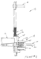
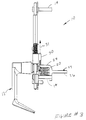
- a door lever assembly 10 for use in single (as shown in Figure 7) or double door applications includes a lever handle 12 and mounting studs 14 for a trim housing 16. Turning the lever handle 12 results in movement of a lift arm 24, which in turn engages and moves connected vertical rods that operate retraction or extension of a door latch.
- the lever handle 12 is of conventional design.
- the trim housing 16 can be attached to a door by engagement with mounting studs 14, which are typically threaded to allow easy screw attachment or disengagement.
- the trim housing 16 supports on its interior permanently attached weld studs 44.
- the weld studs 44 retain a plate 40 that defines therethrough two door lock apertures 38.
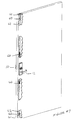
- a mechanism for locking the door can be attached to extend through the trim housing 16 to engage a blocking slide 45 of a door latch assembly 60.
- the door latch assembly includes vertically directed rods 62 movably connected to latches 61.
- the blocking slide 45 is moved upward or downward by rotation of a key cylinder 46 of the door lock mechanism.
- the lift arm 24 typically is constructed from a single integral piece of metal to have a flat lock engaging portion 26 and a flat spring engaging portion 28 joined by a curved intermediary portion. As shown in Figure 1, the lock engaging portion 26 engages the door latch assembly for retraction of the door latch, and can be prevented from movement by contact with the blocking slide 45 when the blocking slide 45 is positioned in its locked position.
- the spring engaging portion 28 of the lift arm is conformably attached to an over-ride assembly 18 that includes an over-ride spring 20.
- the over-ride spring 20 is typically configured to have a high spring constant, and under normal operating torque is essentially inelastic.
- a preload of approximately 70 pounds (36.75 Kg) is commonly imparted to the spring to result in an initial lever torque of about 10 foot-pounds (13.56 Nm).
- the preload force will be overcome and the spring 20 will begin to compress.
- the exact spring material and configuration can be varied, and it is even possible to use elastomeric materials in place of coiled springs as necessary.
- the spring engaging portion 28 of the lift arm 24 is also attached to a vertically movable slider 30.
- the slider 30 is a generally flat plate that is vertically movable with the trim housing 16. Rotation of an eccentrically configured cam 42 causes a cam wing 43 to upwardly push the slider 30, which in turn upwardly impels the lift arm 24.
- the slider 30 has an attached elastomer 36 for engagement with a stop plate 34 defined by the lower edge of the plate 40.
- lift springs 32 are attached between the slider 30 and plate 40. The lift springs are biased to normally push the slider 30 downward, which in turn acts to rotate the cam 42 and return the lever to a horizontal position.
- the door lever handle 12 (not indicated in the Figure for clarity) can be connected by a pin (not shown) to a lever connection site 47 defined at one end of a shaft 48.
- a shear pin 49 having a plurality of flat edges 50 is attached.
- the shear pin 49 fits into a shear pin connection site 51 having matching flat edged walls 52 defined by the cam 42.
- the shear pin 49 extends outward in one direction for engagement with the cam 42. As long as torque is maintained with predefined limits, rotation of the door lever handle 12 results in rotation of the shaft 48, and consequent rotation of the shear pin connected cam 42.
- the bias of the lift springs 32 maintains the door lever handle 12 in a substantially horizontal position to allow easy grasping of the handle by a user desiring to open a door.
- the handle 12 is rotated downward, consequently rotating the shaft 48 and shear pin 49 connected cam 42.
- rotation of the eccentrically configured cam 42 is converted into upward, linearly directed movement 31 of the slider 30 as the wing 43 of the cam engages and impels the slider 30 upward against the biasing force exerted by the lift springs 32.
- Movement of the slider 30 also causes movement of the connected lift arm 24.
- the lift arm 24 is raised, connected vertical rods of the door latch assembly are also moved to release a door latch and allow opening of the door.
- the over-ride spring 20 is essentially uncompressed due to its high spring constant and the relatively low compression forces exerted.
- Rotation of the lever handle beyond about 50 to 55 degrees from horizontal, such as shown in the Figures is impeded by interaction of the elastomer 36 attached to the slider and the contacting the stop plate 34. Further attempts to rotate the handle will cause the elastomer to compress, allowing the cam wing 43 to slip past the slider 30 so that it is no longer engaged.
- an optional stop 53 can be provided to engage and prevent additional rotation of the cam past 90 degrees downward from the initial horizontal lever position.
- the cam 42 can be rotated 360 degrees back to its original position.
- Operation of the lever handle is altered when the blocking slide is moved downward into a locking position.
- the blocking slide prevents upward movement of the lift arm 24. Since movement of the lift arm 24 is prevented, movement of the connected slide, cam, shaft, and door lever handle is also inhibited. Someone trying to open the door would realize from the resistance to movement of the door lever handle that the door is locked.
- the present invention allows the normal operation and use of a door lever assembly that is substantially identical to conventional door lever assemblies when normal forces are exerted.
- the present mechanism disengages when in the unlocked position to prevent damage to the door lever assembly.
- the novel door lever assembly absorbs blows (by the over-ride spring) and then disengages to prevent damage. Because of the use of the over-ride spring and the elastomer/stop plate interaction, in single door applications there will be typically no need to rely on shear pin failure to prevent damage to the door lever assembly. For double door applications, shear pin failure may still be needed as a last resort should entry attempts persist, but as compared to conventional devices, the improved shear pin design and placement make shear pin failure both easier to rely upon and easier to replace.
Landscapes
- Engineering & Computer Science (AREA)
- Mechanical Engineering (AREA)
- Lock And Its Accessories (AREA)
Claims (10)
- Drückerhandgriffanordnung zum Betätigen einer Falle einer verriegelbaren Türfallenanordnung, wobei die Türfallenanordnung eine entriegelte und eine verriegelte Stellung hat. mit beweglichen Stangen (62), um in der unverriegelten Stellung die genannte Türfalle zu lösen. und mit einem Blockierschieber (45). der in die verriegelte Stellung bewegbar ist, um eine Bewegung der vertikalen Stangen und der damit verbundenen Türfalle zu verhindern. wobei die Drückerhandgriffanordnung aufweist:eine Durchrutschfeder (20), die zwischen dem Schieber (30) und dem Hebearm (24) angebracht ist, wobei die Durchrutschfeder (20) eine Bewegung des Schiebers (30) auf den Hebearm zu überträgt. um den Hebearm und die angeschlossenen Stangen zu heben, wenn sich die Türfallenanordnung in ihrer unverriegelten Stellung befindet, und wobei die Durchrutschfeder (20) in Reaktion auf eine Schieberbewegung zusammengedrückt wird, ohne den Hebearm zu bewegen, wenn der Blockierschieber (45) so gestellt ist, daß er eine Bewegung des Hebearms (24) blockiert, wenn sich die Türfallenanordnung in ihrer verriegelten Stellung befindet.einen Drückerhandgriff (12), der mit einen Blendengehäuse (16) drehbar verbunden ist.einen Nocken (42). der betriebsmäßig mit dem Drückerhandgriff verbunden ist und so angeordnet ist. daß er in sich in Reaktion auf eine Drehung des Drückerhandgriffs dreht,einen Schieber (30), der in Reaktion auf eine Drehung des Nocken bewegbar ist,einen Hebearm (24), der mit den vertikalen Stangen der Türfallenanordnung verbunden ist, gekennzeichnet durch
- Drückerhandgriffanordnung nach Anspruch 1, mit einer Welle (48), die zwischen dem Drückerhandgriff und dem Nocken angebracht ist, mit einem Scherstift (49), der die Welle an dem Nocken befestigt.
- Drückerhandgriffanordnung nach Anspruch 2, bei der der Scherstift (49) wenigstens eine flache Seite (50) aufweist, um mit einer durch den Nocken definierten flachen Wand in Kontakt zu kommen.
- Drückerhandgriffanordnung nach Anspruch 2, bei der sich der Scherstift (49) aus der Welle nach außen in nur eine Richtung erstreckt, um den Nocken zu berühren.
- Drückerhandgriffanordnung nach einem der vorhergehenden Ansprüche, mit einer Halteplatte (34), die an dem Blendengehäuse (16) angebracht ist; und mit einer zusammendrückbaren Hebefeder (32), die zwischen der Halteplatte und dem Schieber angeordnet ist, um zusammengedrückt zu werden, wenn sich der Schieber in Richtung auf die Halteplatte zu bewegt. und um zu expandieren, um den Schieber weg von der Halteplatte zu bewegen und den Drückerhandgriff (12) in eine ursprüngliche Stellung zurückzubringen, wenn der Drücker losgelassen wird.
- Drückerhandgriffanordnung nach einem der vorhergehenden Ansprüche, wobei eine oder die Halteplatte (34) am Blendengehäuse (16) angebracht ist und ein Elastomer (36) an dem Schieber angebracht ist, um die Halteplatte zu berühren, wenn sich der Schieber in die Nachbarschaft der Halteplatte bewegt.
- Drückerhandgriffanordnung nach Anspruch 6, bei der der Nocken so gestaltet ist, daß er nach Berührung des Elastomers und der Halteplatte hinter den Gleiter rutscht. um eine kreisförmige Drehung des Drückerhandgriffs zu ermöglichen.
- Drückerhandgriffanordnung nach Anspruch 6 oder 7, mit einem Anschlag (53), der am Blendengehäuse in der Nähe des Nockens (42) angebracht ist. wobei der Anschlag so positioniert ist, daß er den Nocken berührt und eine weitere Drehung des Drückerhandgriffs verhindert, nachdem sich das Elastomer und die Halteplatte berühren.
- Drückerhandgriffanordnung nach einem der vorhergehenden Ansprüche, bei der der Drückerhandgriff in einer ursprünglichen Stellung im Betrieb im wesentlichen horizontal ausgerichtet ist, und bei dem der Nocken sich von einem bewegenden Kontakt mit dem Schieber löst. wenn der Drückerhandgriff über eine im wesentlichen vertikale Stellung hinaus gedrängt wird.
- Drückerhandgriffanordnung nach einem der vorhergehenden Ansprüche, wobei der Drücker für eine Doppeltür gedacht ist. bei dem ein Anschlag oder der genannte Anschlag am Blendengehäuse angebracht ist und so positioniert ist, daß er den Nocken berührt und eine Drehung über eine vorbestimmte Stellung hinaus verhindert.
Applications Claiming Priority (2)
| Application Number | Priority Date | Filing Date | Title |
|---|---|---|---|
| US08/084,102 US5445423A (en) | 1993-07-01 | 1993-07-01 | Breakaway lever clutch |
| US84102 | 1993-07-01 |
Publications (2)
| Publication Number | Publication Date |
|---|---|
| EP0633372A1 EP0633372A1 (de) | 1995-01-11 |
| EP0633372B1 true EP0633372B1 (de) | 1998-12-16 |
Family
ID=22182897
Family Applications (1)
| Application Number | Title | Priority Date | Filing Date |
|---|---|---|---|
| EP94304729A Expired - Lifetime EP0633372B1 (de) | 1993-07-01 | 1994-06-28 | Türdrückeranordnung |
Country Status (5)
| Country | Link |
|---|---|
| US (1) | US5445423A (de) |
| EP (1) | EP0633372B1 (de) |
| CA (1) | CA2127217A1 (de) |
| DE (1) | DE69415225T2 (de) |
| NZ (2) | NZ260880A (de) |
Cited By (1)
| Publication number | Priority date | Publication date | Assignee | Title |
|---|---|---|---|---|
| AU2016204187B2 (en) * | 2015-10-14 | 2018-02-22 | Allegion (Australia) Pty Ltd | A lock assembly |
Families Citing this family (24)
| Publication number | Priority date | Publication date | Assignee | Title |
|---|---|---|---|---|
| US5570916A (en) * | 1993-12-27 | 1996-11-05 | Von Duprin, Inc. | Breakaway lever clutch with vertical lift trim |
| US5564760A (en) * | 1994-01-10 | 1996-10-15 | Von Duprin, Inc. | Door lever assembly having non-machined fastenerless trim |
| US5832758A (en) * | 1995-02-22 | 1998-11-10 | Vacant Property Security Limited | Locking mechanism |
| US5658026A (en) * | 1995-09-05 | 1997-08-19 | Von Duprin, Inc. | Door handle locking mechanism with dual function springs |
| US5664816A (en) * | 1995-09-05 | 1997-09-09 | Von Duprin, Inc. | Lever handle assembly with field adjustable tailpiece and lever handing |
| US5816086A (en) * | 1996-08-15 | 1998-10-06 | Schlage Lock Company | Axial moving pushbutton for a lock having rotary locking and release motions |
| CA2234334A1 (en) * | 1997-05-05 | 1998-11-05 | Alan K. Uyeda | Handle movement clutch mechanism |
| US6616633B1 (en) * | 1997-09-19 | 2003-09-09 | Alaris Medical Systems, Inc. | Apparatus and method for air-in-line detection |
| GB9920869D0 (en) * | 1999-09-04 | 1999-11-10 | Meritor Light Vehicle Sys Ltd | Latch |
| US6641186B2 (en) * | 2002-01-28 | 2003-11-04 | Miao-Hsueh Tsai | Combination of mounting plate and rose for door locks |
| US20050179266A1 (en) * | 2004-02-17 | 2005-08-18 | Oscar Romero | Interconnected chassis for a lock set |
| US7257973B2 (en) | 2004-02-17 | 2007-08-21 | Newfrey, Llc | Chassis for a lock set |
| US20050192101A1 (en) * | 2004-02-26 | 2005-09-01 | Kurt Businger | Door handle assembly |
| US20090188283A1 (en) * | 2008-01-29 | 2009-07-30 | Hsu Yueh-Chiac | Safety and burglarproof transversal lock |
| CN201874313U (zh) * | 2010-11-25 | 2011-06-22 | 易建华 | 一种机械锁的离合保护机构 |
| CN104302856B (zh) | 2012-01-11 | 2016-12-07 | 西勒奇制锁有限责任公司 | 用于门把手的安全机构 |
| USD706112S1 (en) * | 2012-09-18 | 2014-06-03 | Larson Manufacturing Company Of South Dakota, Inc. | Shaped spindle of a door handle for operating a door lock box |
| USD734652S1 (en) | 2012-09-18 | 2015-07-21 | Larson Manufacturing Company Of South Dakota, Inc. | Shaped spindle of a door handle for operating a door lock box |
| CN103334637B (zh) * | 2013-07-19 | 2015-07-01 | 邓建春 | 一种机械锁芯及使用该锁芯的锁 |
| WO2016187542A1 (en) * | 2015-05-21 | 2016-11-24 | Yale Security Inc. | Escutcheon mounting plate |
| CN105201281B (zh) * | 2015-09-11 | 2020-08-04 | 赵振威 | 一种可换锁芯的木门带锁拉手 |
| CN106013960B (zh) * | 2016-06-27 | 2018-06-01 | 佛山市思歌锁业科技有限公司 | 一种防止通过猫眼开锁的门锁装置 |
| EP3665345B1 (de) * | 2017-08-08 | 2026-01-21 | Schlage Lock Company LLC | Reduktion und bewertung der geräusche eines türbeschlags |
| US11225332B2 (en) * | 2018-02-26 | 2022-01-18 | James Thomas Pike | Unmanned aerial vehicle provided with detachable motor arms |
Family Cites Families (16)
| Publication number | Priority date | Publication date | Assignee | Title |
|---|---|---|---|---|
| US1744957A (en) * | 1928-07-02 | 1930-01-28 | Simon J Fox | Outside door handle for vehicles |
| US2138856A (en) * | 1933-04-17 | 1938-12-06 | Frank E Best Inc | Lock |
| US2160611A (en) * | 1936-12-03 | 1939-05-30 | Grover C Alexander | Automobile door handle |
| US2464603A (en) * | 1946-09-26 | 1949-03-15 | Sargent & Co | Door lock |
| DE860156C (de) * | 1948-11-19 | 1952-12-18 | Tack & Gabel | Fallenschloss fuer Tueren an Fahrzeugen, insbesondere Kraftwagen |
| US2873990A (en) * | 1956-11-06 | 1959-02-17 | Rose Grossman | Closure fastener |
| US3990277A (en) * | 1976-04-06 | 1976-11-09 | Tre Corporation | Lock mechanism with disengageable knob |
| US4418552A (en) * | 1979-10-22 | 1983-12-06 | Nolin Roger J | Simultaneously locking and unlocking dead bolt and lock latch with panic unlocking |
| US4427223A (en) * | 1981-08-03 | 1984-01-24 | Von Duprin, Inc. | Latching device |
| GB2161530B (en) * | 1984-07-14 | 1987-10-21 | Ford Motor Co | Electrically controlled door locking system |
| US4847950A (en) * | 1986-08-01 | 1989-07-18 | Von Duprin, Inc. | Self retained axle pin assembly for shear application |
| US4920773B1 (en) * | 1988-02-08 | 1997-01-14 | Yale Security Inc | Door lock having disengaged outer lever handle when in the locked condition and means to bias the hadle toward horizontal position |
| US4982986A (en) * | 1988-12-19 | 1991-01-08 | Adams Rite Manufacturing Company | Lever/knob actuated entry mechanism |
| US4934800A (en) * | 1989-05-18 | 1990-06-19 | Adams Rite Manufacturing Company | Low cost lever handle entry function |
| US5024472A (en) * | 1990-04-09 | 1991-06-18 | Von Duprin, Inc. | Flushbolt actuator assembly |
| US5205596A (en) * | 1992-08-24 | 1993-04-27 | Cole-Sewell Corporation | Door latch member |
-
1993
- 1993-07-01 US US08/084,102 patent/US5445423A/en not_active Expired - Lifetime
-
1994
- 1994-06-28 DE DE69415225T patent/DE69415225T2/de not_active Expired - Fee Related
- 1994-06-28 EP EP94304729A patent/EP0633372B1/de not_active Expired - Lifetime
- 1994-06-29 NZ NZ260880A patent/NZ260880A/en unknown
- 1994-06-29 NZ NZ314715A patent/NZ314715A/en unknown
- 1994-06-30 CA CA002127217A patent/CA2127217A1/en not_active Abandoned
Cited By (1)
| Publication number | Priority date | Publication date | Assignee | Title |
|---|---|---|---|---|
| AU2016204187B2 (en) * | 2015-10-14 | 2018-02-22 | Allegion (Australia) Pty Ltd | A lock assembly |
Also Published As
| Publication number | Publication date |
|---|---|
| NZ314715A (en) | 1997-10-24 |
| EP0633372A1 (de) | 1995-01-11 |
| CA2127217A1 (en) | 1995-01-02 |
| NZ260880A (en) | 1997-12-19 |
| DE69415225T2 (de) | 1999-05-20 |
| DE69415225D1 (de) | 1999-01-28 |
| US5445423A (en) | 1995-08-29 |
Similar Documents
| Publication | Publication Date | Title |
|---|---|---|
| EP0633372B1 (de) | Türdrückeranordnung | |
| EP0662554B1 (de) | Türdrückeranordnung | |
| EP0662555B1 (de) | Türdrückeranordnung | |
| US7523968B2 (en) | Reach out lock | |
| US4583382A (en) | Reversible latch assembly with integrated function | |
| US4529234A (en) | Electrical operating means for door lock mechanisms | |
| KR100415001B1 (ko) | 모르티스 로크용 레버 핸들 제어기 | |
| WO2007000763A1 (en) | Mortise lock | |
| CA3074062C (en) | KEY OVERRIDE FOR ELECTROMECHANICAL MULTIPOINT LOCKING DEVICE | |
| US5484179A (en) | Failsafe electric locking lever trim | |
| EP0678644A1 (de) | Wegnehmbare Stützeeinheit mit Zylinderschloss | |
| US5564760A (en) | Door lever assembly having non-machined fastenerless trim | |
| KR101356668B1 (ko) | 록 기구 | |
| EP1335085A1 (de) | Verschluss für Schiebetür oder -tor | |
| EP1495202B1 (de) | Elektrisch steuerbares türschloss | |
| US5516161A (en) | Breakaway lever clutch with cam drive pin | |
| EP4575153A1 (de) | Verriegelung für ein schiebeverschlusselement und verschlusssystem damit | |
| AU2020204253B2 (en) | Double door lock assembly | |
| AU9607498A (en) | A lock | |
| AU2019210627B1 (en) | A latch assembly | |
| AU5352900A (en) | A lock for a moveable wing | |
| GB2381036A (en) | A handle controlling a locking device and a blocking device | |
| JPS5925063B2 (ja) | ドア錠用非常開放受け金具アセンブリ | |
| MXPA01007085A (en) | Lever handle controller for mortise lock |
Legal Events
| Date | Code | Title | Description |
|---|---|---|---|
| PUAI | Public reference made under article 153(3) epc to a published international application that has entered the european phase |
Free format text: ORIGINAL CODE: 0009012 |
|
| AK | Designated contracting states |
Kind code of ref document: A1 Designated state(s): DE FR GB IT |
|
| 17P | Request for examination filed |
Effective date: 19950118 |
|
| 17Q | First examination report despatched |
Effective date: 19970321 |
|
| GRAG | Despatch of communication of intention to grant |
Free format text: ORIGINAL CODE: EPIDOS AGRA |
|
| GRAG | Despatch of communication of intention to grant |
Free format text: ORIGINAL CODE: EPIDOS AGRA |
|
| GRAH | Despatch of communication of intention to grant a patent |
Free format text: ORIGINAL CODE: EPIDOS IGRA |
|
| GRAH | Despatch of communication of intention to grant a patent |
Free format text: ORIGINAL CODE: EPIDOS IGRA |
|
| GRAA | (expected) grant |
Free format text: ORIGINAL CODE: 0009210 |
|
| AK | Designated contracting states |
Kind code of ref document: B1 Designated state(s): DE FR GB IT |
|
| REF | Corresponds to: |
Ref document number: 69415225 Country of ref document: DE Date of ref document: 19990128 |
|
| ITF | It: translation for a ep patent filed | ||
| ET | Fr: translation filed | ||
| PGFP | Annual fee paid to national office [announced via postgrant information from national office to epo] |
Ref country code: FR Payment date: 19990601 Year of fee payment: 6 |
|
| PGFP | Annual fee paid to national office [announced via postgrant information from national office to epo] |
Ref country code: GB Payment date: 19990602 Year of fee payment: 6 |
|
| PGFP | Annual fee paid to national office [announced via postgrant information from national office to epo] |
Ref country code: DE Payment date: 19990603 Year of fee payment: 6 |
|
| K2C3 | Correction of patent specification (complete document) published |
Effective date: 19981216 |
|
| PLBE | No opposition filed within time limit |
Free format text: ORIGINAL CODE: 0009261 |
|
| STAA | Information on the status of an ep patent application or granted ep patent |
Free format text: STATUS: NO OPPOSITION FILED WITHIN TIME LIMIT |
|
| 26N | No opposition filed | ||
| PG25 | Lapsed in a contracting state [announced via postgrant information from national office to epo] |
Ref country code: GB Free format text: LAPSE BECAUSE OF NON-PAYMENT OF DUE FEES Effective date: 20000628 |
|
| GBPC | Gb: european patent ceased through non-payment of renewal fee |
Effective date: 20000628 |
|
| PG25 | Lapsed in a contracting state [announced via postgrant information from national office to epo] |
Ref country code: FR Free format text: LAPSE BECAUSE OF NON-PAYMENT OF DUE FEES Effective date: 20010228 |
|
| REG | Reference to a national code |
Ref country code: FR Ref legal event code: ST |
|
| PG25 | Lapsed in a contracting state [announced via postgrant information from national office to epo] |
Ref country code: DE Free format text: LAPSE BECAUSE OF NON-PAYMENT OF DUE FEES Effective date: 20010403 |
|
| PG25 | Lapsed in a contracting state [announced via postgrant information from national office to epo] |
Ref country code: IT Free format text: LAPSE BECAUSE OF NON-PAYMENT OF DUE FEES;WARNING: LAPSES OF ITALIAN PATENTS WITH EFFECTIVE DATE BEFORE 2007 MAY HAVE OCCURRED AT ANY TIME BEFORE 2007. THE CORRECT EFFECTIVE DATE MAY BE DIFFERENT FROM THE ONE RECORDED. Effective date: 20050628 |