EP0633567B1 - Suspension de moteur de cabestan - Google Patents
Suspension de moteur de cabestan Download PDFInfo
- Publication number
- EP0633567B1 EP0633567B1 EP19930118137 EP93118137A EP0633567B1 EP 0633567 B1 EP0633567 B1 EP 0633567B1 EP 19930118137 EP19930118137 EP 19930118137 EP 93118137 A EP93118137 A EP 93118137A EP 0633567 B1 EP0633567 B1 EP 0633567B1
- Authority
- EP
- European Patent Office
- Prior art keywords
- support means
- bridge
- magnetic tape
- tape recorder
- motor
- Prior art date
- Legal status (The legal status is an assumption and is not a legal conclusion. Google has not performed a legal analysis and makes no representation as to the accuracy of the status listed.)
- Expired - Lifetime
Links
Images

Classifications
-
- H—ELECTRICITY
- H02—GENERATION; CONVERSION OR DISTRIBUTION OF ELECTRIC POWER
- H02K—DYNAMO-ELECTRIC MACHINES
- H02K5/00—Casings; Enclosures; Supports
- H02K5/26—Means for adjusting casings relative to their supports
-
- G—PHYSICS
- G11—INFORMATION STORAGE
- G11B—INFORMATION STORAGE BASED ON RELATIVE MOVEMENT BETWEEN RECORD CARRIER AND TRANSDUCER
- G11B15/00—Driving, starting or stopping record carriers of filamentary or web form; Driving both such record carriers and heads; Guiding such record carriers or containers therefor; Control thereof; Control of operating function
- G11B15/18—Driving; Starting; Stopping; Arrangements for control or regulation thereof
- G11B15/26—Driving record carriers by members acting directly or indirectly thereon
- G11B15/28—Driving record carriers by members acting directly or indirectly thereon through rollers driving by frictional contact with the record carrier, e.g. capstan; Multiple arrangements of capstans or drums coupled to means for controlling the speed of the drive; Multiple capstan systems alternately engageable with record carrier to provide reversal
-
- G—PHYSICS
- G11—INFORMATION STORAGE
- G11B—INFORMATION STORAGE BASED ON RELATIVE MOVEMENT BETWEEN RECORD CARRIER AND TRANSDUCER
- G11B15/00—Driving, starting or stopping record carriers of filamentary or web form; Driving both such record carriers and heads; Guiding such record carriers or containers therefor; Control thereof; Control of operating function
- G11B15/675—Guiding containers, e.g. loading, ejecting cassettes
- G11B15/6751—Guiding containers, e.g. loading, ejecting cassettes with movement of the cassette parallel to its main side, i.e. front loading
- G11B15/67521—Guiding containers, e.g. loading, ejecting cassettes with movement of the cassette parallel to its main side, i.e. front loading of cassette with internal belt drive
Definitions
- the present invention relates to a magnetic tape recorder having a tape drive bridge arranged for movement toward and away from a magnetic tape cassette loaded in the recorder, the tape drive bridge carrying the tape drive motor and a magnetic head, the motor having a drive capstan arranged coaxially thereon and the cassette having a cassette roller and drive belt arrangement for turning the cassette reels, the cassette roller being in rolling contact with said capstan when the tape drive bridge is moved toward said magnetic tape cassette, and said magnetic head engaging the magnetic tape for reading/writing magnetic signals.
- the system should be capable for easy mounting and dismounting of the motor.
- the capstan and cassette roller are brought together for abutting relationship, the capstan can be inadvertently tilted from the vertical axis compared to the vertical axis of the cassette roller, resulting in undesirable wear on the rolling parts, as well as imprecise performance.
- a support system for a drive motor within a tape drive that provides an attachment bracket including a cylindrical aperture into which the drive motor is inserted.
- the diameters of the cylindrical aperture and of the motor are dimensioned, such that the motor can be tilted in order to induce an improved attachment of the cassette capstan and the drive roller.
- a biasing arrangement is provided that acts on the attachment bracket.
- the invention is defined in claim 1.
- a motor mount arrangement is provided between a tape drive and a tape drive bridge, the bridge disposed for movement toward and away from a magnetic tape cassette loaded in the read/write unit for causing the engagement between a drive capstan mounted coaxially on an output shaft of the motor and a cassette roller held rotatably within the tape cassette for progressing the magnetic tape from reel to reel, wherein the motor support arrangement comprises a pivotable or swivel support between the motor and the bridge allowing the motor output shaft axis to tilt about a line perpendicular to the axis, tilting the axis toward or away from the cartridge roller.
- the axis of swivel is approximately perpendicular to the approaching direction of the drive capstan toward the cassette roller.
- the support arrangement comprises an approximately circular aperture formed through the bridge, having diametrically opposed dimples formed in side walls thereof, and the motor having semi-spherical buttons formed on opposite sides thereof in registry with the dimples.
- At least one of the dimples is formed on a flexible finger portion which partially defines the circular aperture, the flexible finger portion movable toward and away from a center line of said aperture in an approximate radial direction, to release the buttons from the dimples for removal or installation of the motor within the aperture.
- the flexible finger portion is biased toward the center line of the aperture by a plastic bushing arranged on a backside of the flexible finger portion between the flexible finger portion and a more rigid portion of the bridge.
- buttons are arranged on a horizontal axis approximately perpendicular to the approaching direction of the motor, and the motor capstan, toward the cassette roller, or at least the axis is approximately perpendicular to a tangent line of the swinging arc of the bridge near to the point of contact between the cassette roller and the motor capstan.
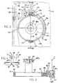
- Figure 1 is a partially schematic, plan view of a read/write unit with cassette with a top portion of the unit removed.
- Figure 2 is a bottom plan view of a portion of the unit shown in Figure 1.
- Figure 3 is a partial sectional view taken generally along line III-III of Figure 2.
- Figure 4 is a partial elevational view of the motor/drive capstan/cartridge roller arrangement of the present invention.
- FIG. 1 illustrates a magnetic tape recorder 10 holding a magnetic tape cassette 16 therein.
- the magnetic tape cassette 16 comprises a first tape spool 18, a second tape spool 20, a supply of magnetic tape 24 wrapped around the spools and two guide rollers 26,28.
- the cassette also provides a cassette roller 30 having a belt 34 wrapped around the cassette roller and a first and second belt rollers 38, 40 arranged at approximately the corners of the cassette 16.
- the belt 34 is circulated around the cassette roller 30 and the belt rollers 38, 40. Because the belt is partially wrapped around the spools 18, 20, the circulation of the belt causes, by friction, rotation of the spools and circulation of the magnetic tape 24.
- the described construction of the magnetic tape cassette is known.
- the read/write unit 10 includes a bridge 46 which is an elongate member rotatable about a pin means 48 under influence of a gear control means 52 shown as a schematic box for simplicity.
- the gear control means 52 provides a rotating lever arm 54 which provides a pin 56 held in a slot 58 arranged formed through the bridge 46 at a distance from the pin means 48. Rotation of the lever 54 progresses the pin 56 through the slot 58 and exerts a force onto the bridge 46 which creates a moment about the pin means 48. This force pivots the bridge 46 about the pin means 48.
- Mounted for movement with the bridge 46 is a motor 64 having an output shaft 66 arranged generally vertically.
- a capstan 68 is mounted coaxially with the output shaft 66 and fixed thereto for rotation.
- a magnetic head 74 is also mounted for movement with the bridge 46.
- the gear control 52 can pivot the bridge to move the capstan 68 into rolling abutting engagement with the cassette roller 30, and move the magnetic read/write head 74 into contact with the magnetic tape 24.
- FIG. 2 illustrates the manner in which the motor is supported on the bridge 46.
- the bridge comprises a relatively rigid lattice-type frame having a journal portion 78 surrounding the pin means 48, and rigidly connected thereto are divergent leg portions 80, 82 which provide a space 84 therebetween which can house other components of the read/write unit 10.
- the leg portions 80, 82 merge together at an intersection 88.
- a rigid portion 92 of the bridge continues from the intersection 88 for approximately 180° around the circumference of the motor 64 to a location 94.
- a flexible finger portion 96 continues around counterclockwise of the motor shown in Figure 2 and terminates in a free end 98.
- the leg portion 82, the rigid portion 92 and the flexible finger portion 96 define substantially a circular aperture 100 wherein the motor is located.
- the leg portion 82 and the flexible finger portion 96 overlap to define a space 102 therebetween wherein an elastomeric bushing 106 is installed.
- a side wall 108 of the motor 64 provide two semi-spherical buttons 110, 112 which protrude outwardly and are diametrically opposed across the motor.
- the buttons 110, 112 interfit at least partially in dimples 116, 118 arranged in the rigid portion 92 and the flexible finger portion 96 respectively.
- the flexible finger portion 96 by way of its natural cantilever resiliency and/or the backing of the bushing 106, resiliently holds the buttons 110, 112 within the dimples 116, 118. Because the buttons 110, 112 are semi-spherical and the dimples 116, 118 are also semi-spherical, the buttons can rotate within the dimples 116, 118 about an axis Z.
- Figure 3 illustrates in cross section the fitment of the motor 64 between the rigid portion 92 and the flexible finger portion 96 via the spherical buttons 110, 112. Additionally, Figure 3 illustrates that the capstan 68 provides a frictional outside layer 68a, such as a rubber covering for advantageous friction with the cassette roller 30.
- the pin means 48 is shown as an elongate rivet having a head 48a and an expanded rivet tail 48b which captures the bridge 46 rotatably onto a tab 124 of a stationary bottom cover plate 126 of the read/write machine 10.
- Figure 4 illustrates that the motor 64 is pivotable according to the arcuate direction C toward and away from the cassette roller 30.
- the combination of pivoting about the Z axis and the rotating by the bridge about the Y axis brings the capstan 68 in proper compatible axial parallelism with the cartridge roller 30, i.e., the axis Y' is parallel to the axis Y''.
- An overlying resilient cover 140 provides a resilient downward force on the motor 64 to counterbalance the counterclockwise moment about the Z axis on the motor 64 caused by the cassette roller 30 exerting a force on the capstan 68.
- the flexible finger portion 96 can be moved at its distal end 98 in the direction B to increase or decrease the clear distance between the flexible finger portion dimple 118 and the base portion dimple 116 to install or remove the motor 64.
- the bushing 106 also aids in dampening vibration from the motor or to the motor to/from other elements of the read/write unit.
Landscapes
- Engineering & Computer Science (AREA)
- Power Engineering (AREA)
- Adjustment Of The Magnetic Head Position Track Following On Tapes (AREA)
- Recording Or Reproducing By Magnetic Means (AREA)
- Motor Or Generator Frames (AREA)
Claims (14)
- Enregistreur sur bande magnétique (10) ayant un dispositif, en pont, d'entraínement de bande (46) disposé pour se déplacer en se rapprochant et en s'éloignant d'une cassette de bande magnétique (16) chargée dans ledit enregistreur (10), ledit dispositif, en pont, d'entraínement de bande (46) supportant également une tête magnétique (74) et un moteur d'entraínement de bande (64) entraínant un cabestan d'entraínement (68), un ensemble de support pour ledit moteur d'entraínement de bande (64), comprenant :caractérisé en ce quedes premiers moyens de support (110, 112) disposés sur ledit moteur d'entraínement de bande (64) ;des seconds moyens de support (116, 118) disposés sur ledit dispositif, en pont, d'entraínement de bande (46), engageant lesdits premiers moyens de support (110, 112) ;dans lequel les uns desdits premiers et seconds moyens de support comprennent une saillie (110, 112) et les autres respectifs desdits premiers et seconds moyens de support comprennent un axe (116, 118) pour tenir ladite saillie (110, 112) ;lesdits seconds moyens de support (116, 118) étant au moins partiellement disposés sur une partie flexible (96, 98) dudit dispositif en pont (46), la flexion sélective de celui-ci libèrent lesdits premiers moyens de support (110, 112) de l'engagement avec lesdits seconds moyens de support.
- Enregistreur sur bande magnétique (10) selon la revendication 2, dans lequel ladite partie flexible (96, 98) est disposée sur ledit dispositif en pont (46), à l'opposé d'une partie plus rigide (92) dudit dispositif (46), et un élément en élastomère (106) est disposé entre eux pour solliciter ladite partie flexible (96, 98) en direction dudit moteur (64).
- Enregistreur sur bande magnétique (10) selon la revendication 1 ou 2, dans lequel ladite partie flexible (96, 98) comprend un doigt en arc limitant partiellement une circonférence dudit moteur (64).
- Enregistreur sur bande magnétique (10) selon l'une des revendications précédentes, dans lequel lesdits premiers moyens de support (110, 112) comprennent des saillies sphériques et lesdits seconds moyens de support (116, 118) comprennent des cavités sphériques maintenant lesdites saillies sphériques.
- Enregistreur sur bande magnétique (10) selon l'une quelconque des revendications précédentes, dans lequel la flexion de ladite partie flexible (96, 98) libère au moins l'une desdites saillies (112) de l'une desdites cavités (118).
- Enregistreur sur bande magnétique (10) selon l'une des revendications précédentes, ayantlesdits premiers moyens de support (110, 112) disposés sur ledit moteur d'entraínement de bande (64) en des positions diamétralement opposées ;lesdits seconds moyens de support (116, 118) disposés pour permettre audit moteur d'entraínement de bande (64) de pivoter autour d'un axe Z défini entre lesdits premiers moyens de support (110, 112).
- Enregistreur sur bande magnétique (10) selon la revendication 6, dans lequel lesdits premiers moyens de support (110, 112) comprennent des boutons relevés sur ledit moteur d'entraínement de bande (64) et s'étendant radialement vers l'extérieur ; etlesdits seconds moyens de support (116, 118) comprennent des évidements formés dans ledit dispositif en pont (46), lesdits boutons relevés étant en correspondance avec lesdits évidements.
- Enregistreur sur bande magnétique (10) selon la revendication 6 ou 7, dans lequel lesdits boutons relevés (110, 112) comprennent des sphères partielles et lesdits évidements (116, 118) comprennent des cavités sphériques partielles.
- Enregistreur sur bande magnétique (10) selon l'une des revendications 6 à 8, dans lequel lesdits seconds moyens de support (116, 118) sont disposés sur une partie flexible (96, 98) dudit dispositif en pont (46) qui est diamétralement flexible pour se rapprocher et s'écarter desdits premiers moyens de support (110, 112), permettant le désengagement desdits premiers moyens de support (110, 112) desdits seconds moyens de support (116, 118) lors de la flexion de ladite partie flexible (96, 98).
- Enregistreur sur bande magnétique (10) selon l'une des revendications 6 à 9, dans lequel ladite partie flexible 96, 98 est disposée en étant contiguë à une partie non flexible (82) dudit dispositif en pont (46), et un élément élastique (106) est intercalé entre eux, la flexion de ladite partie flexible (96, 98) étant influencée par l'élasticité dudit élément élastique (106).
- Enregistreur sur bande magnétique (10) selon l'une des revendications 6 à 10, dans lequel ledit élément élastique 106 comprend une douille en élastomère.
- Enregistreur sur bande magnétique (10) selon la revendication 6, dans lequel ledit dispositif en pont (46) présente un ouverture sensiblement circulaire et ledit moteur 64 comprend un profil sensiblement circulaire et est intercalé en ajustement serré à l'intérieur de ladite ouverture sensiblement circulaire, et définissant partiellement ladite ouverture sensiblement circulaire se trouve une partie de doigt flexible en arc (96, 98) du dispositif en pont (46), et lesdits seconds moyens de support (116, 118) sont disposés au moins partiellement sur ladite partie de doigt flexible (96, 98).
- Enregistreur sur bande magnétique (10) selon la revendication 12, dans lequel ledit dispositif en pont (46) comprend une partie relativement rigide 82 disposée entre un point pivot (Y) dudit dispositif en pont (46) et ladite partie de doigt flexible (97-48), et une douille en plastique (106) disposée entre ladite partie rigide (82) et ladite partie de doigt flexible (96, 98).
- Enregistreur sur bande magnétique (10) selon la revendication 13, dans lequel ledit point pivot "Y" dudit dispositif en pont (46), ladite douille en élastomère et lesdits premiers et seconds moyens de support (116, 112, 116, 118) sont disposés sensiblement selon une ligne (Z).
Applications Claiming Priority (2)
| Application Number | Priority Date | Filing Date | Title |
|---|---|---|---|
| US8878293A | 1993-07-08 | 1993-07-08 | |
| US88782 | 1993-07-08 |
Publications (3)
| Publication Number | Publication Date |
|---|---|
| EP0633567A2 EP0633567A2 (fr) | 1995-01-11 |
| EP0633567A3 EP0633567A3 (fr) | 1995-03-08 |
| EP0633567B1 true EP0633567B1 (fr) | 1998-01-28 |
Family
ID=22213429
Family Applications (1)
| Application Number | Title | Priority Date | Filing Date |
|---|---|---|---|
| EP19930118137 Expired - Lifetime EP0633567B1 (fr) | 1993-07-08 | 1993-11-09 | Suspension de moteur de cabestan |
Country Status (3)
| Country | Link |
|---|---|
| EP (1) | EP0633567B1 (fr) |
| JP (1) | JP2730619B2 (fr) |
| DE (1) | DE69316742T2 (fr) |
Families Citing this family (3)
| Publication number | Priority date | Publication date | Assignee | Title |
|---|---|---|---|---|
| US6023937A (en) * | 1996-12-11 | 2000-02-15 | Carrier Corporation | Compressor mounting arrangement |
| DE69814233T2 (de) | 1997-06-10 | 2003-11-20 | Alps Electric Co., Ltd. | Magnetaufzeichnungs-/Wiedergabegerät |
| JPH1139746A (ja) * | 1997-07-17 | 1999-02-12 | Alps Electric Co Ltd | 磁気記録再生装置 |
Family Cites Families (8)
| Publication number | Priority date | Publication date | Assignee | Title |
|---|---|---|---|---|
| US3698615A (en) * | 1971-02-01 | 1972-10-17 | Motorola Inc | Synchronous motor mounting system for speed control |
| US4085906A (en) * | 1976-12-13 | 1978-04-25 | Three Phoenix Company | Magnetic tape cartridge transport |
| US4199092A (en) * | 1978-10-16 | 1980-04-22 | Omnicomp, Inc. | Flexure mount for capstan motor |
| DE3112802A1 (de) * | 1981-03-31 | 1982-10-14 | Tandberg Data A/S, Oslo | Aufhaengung fuer den schwenkbar gelagerten bandantriebsmotor in einem kassettenmagnetbandgeraet |
| US4573091A (en) * | 1982-11-15 | 1986-02-25 | Cipher Data Products, Inc. | Cartridge tape drive |
| CA1197318A (fr) * | 1982-11-26 | 1985-11-26 | Dwayne G. Vailliencourt | Moteur pour mecanisme d'entrainement d'un ruban |
| JPS6050646A (ja) * | 1983-08-29 | 1985-03-20 | Olympus Optical Co Ltd | テ−プレコ−ダ |
| JPH041942A (ja) * | 1990-04-18 | 1992-01-07 | Sumitomo Electric Ind Ltd | 反射光測定用素子 |
-
1993
- 1993-11-09 DE DE1993616742 patent/DE69316742T2/de not_active Expired - Fee Related
- 1993-11-09 EP EP19930118137 patent/EP0633567B1/fr not_active Expired - Lifetime
-
1994
- 1994-04-08 JP JP6071117A patent/JP2730619B2/ja not_active Expired - Lifetime
Also Published As
| Publication number | Publication date |
|---|---|
| EP0633567A3 (fr) | 1995-03-08 |
| EP0633567A2 (fr) | 1995-01-11 |
| DE69316742D1 (de) | 1998-03-05 |
| JPH07130044A (ja) | 1995-05-19 |
| JP2730619B2 (ja) | 1998-03-25 |
| DE69316742T2 (de) | 1998-05-14 |
Similar Documents
| Publication | Publication Date | Title |
|---|---|---|
| KR880001210Y1 (ko) | 자기디스크 어셈블리 | |
| EP0403651B1 (fr) | Mecanisme d'entrainement de bande | |
| US6327119B1 (en) | Inertial latch for mobile disc drive | |
| KR940004990B1 (ko) | 벨트 구동 테이프 카아트리지의 무진동 스푸울 | |
| US4561609A (en) | Anti-friction and non-oscillating spool for belt driven cartridge | |
| EP0633567A2 (fr) | Suspension de moteur de cabestan | |
| EP0227917B1 (fr) | Dispositif de réglage de tension de bande pour un appareil d'enregistrement/reproduction à cassette | |
| US5239432A (en) | Magnetic tape cassette having a slot for inserting a recording and/or reproducing head therethrough and a magnetic tape recording and/or reproducing apparatus for use with such magnetic tape cassette | |
| US5936793A (en) | Capstan motor for a magnetic recording and reproducing apparatus | |
| EP0169032B1 (fr) | Appareil d'enregistrement et de reproduction pour cassettes de bande magnétique | |
| KR100207239B1 (ko) | 비데오카세트테이프레코더의 핀치레버 구조 | |
| JPH06203431A (ja) | 記録再生装置 | |
| KR200141230Y1 (ko) | 자기기록재생기의 텐션조절장치 | |
| JPH0337146Y2 (fr) | ||
| KR0162386B1 (ko) | 자기기록재생기의 텐션조절장치 | |
| KR0176823B1 (ko) | 자기기록재생기의 텐션조절장치 | |
| EP0012531B1 (fr) | Améliorations aux dispositifs de traitement de bande magnétique | |
| JPH051027Y2 (fr) | ||
| KR960002126Y1 (ko) | 자기기록재생기의 테이프 텐션장치 | |
| KR0117658Y1 (ko) | 하드디스크 드라이브의 액츄에이터장치 | |
| JPH08273242A (ja) | ビデオカセットレコーダ用ピンチローラアセンブリ | |
| JPH0548297Y2 (fr) | ||
| US6866217B2 (en) | Idler mechanism for magnetic tape device and tape device | |
| KR100237034B1 (ko) | 테이프 레코더의 테이프 풀림 방지장치 | |
| JP3218609B2 (ja) | テーププレーヤ |
Legal Events
| Date | Code | Title | Description |
|---|---|---|---|
| PUAI | Public reference made under article 153(3) epc to a published international application that has entered the european phase |
Free format text: ORIGINAL CODE: 0009012 |
|
| AK | Designated contracting states |
Kind code of ref document: A2 Designated state(s): DE FR GB |
|
| PUAL | Search report despatched |
Free format text: ORIGINAL CODE: 0009013 |
|
| AK | Designated contracting states |
Kind code of ref document: A3 Designated state(s): DE FR GB |
|
| 17P | Request for examination filed |
Effective date: 19950811 |
|
| 17Q | First examination report despatched |
Effective date: 19960926 |
|
| GRAG | Despatch of communication of intention to grant |
Free format text: ORIGINAL CODE: EPIDOS AGRA |
|
| GRAG | Despatch of communication of intention to grant |
Free format text: ORIGINAL CODE: EPIDOS AGRA |
|
| GRAH | Despatch of communication of intention to grant a patent |
Free format text: ORIGINAL CODE: EPIDOS IGRA |
|
| GRAH | Despatch of communication of intention to grant a patent |
Free format text: ORIGINAL CODE: EPIDOS IGRA |
|
| GRAA | (expected) grant |
Free format text: ORIGINAL CODE: 0009210 |
|
| AK | Designated contracting states |
Kind code of ref document: B1 Designated state(s): DE FR GB |
|
| PG25 | Lapsed in a contracting state [announced via postgrant information from national office to epo] |
Ref country code: FR Free format text: LAPSE BECAUSE OF FAILURE TO SUBMIT A TRANSLATION OF THE DESCRIPTION OR TO PAY THE FEE WITHIN THE PRESCRIBED TIME-LIMIT Effective date: 19980128 |
|
| REF | Corresponds to: |
Ref document number: 69316742 Country of ref document: DE Date of ref document: 19980305 |
|
| RAP2 | Party data changed (patent owner data changed or rights of a patent transferred) |
Owner name: TANDBERG DATA ASA |
|
| EN | Fr: translation not filed | ||
| PG25 | Lapsed in a contracting state [announced via postgrant information from national office to epo] |
Ref country code: GB Free format text: LAPSE BECAUSE OF NON-PAYMENT OF DUE FEES Effective date: 19981109 |
|
| PLBE | No opposition filed within time limit |
Free format text: ORIGINAL CODE: 0009261 |
|
| STAA | Information on the status of an ep patent application or granted ep patent |
Free format text: STATUS: NO OPPOSITION FILED WITHIN TIME LIMIT |
|
| 26N | No opposition filed | ||
| GBPC | Gb: european patent ceased through non-payment of renewal fee |
Effective date: 19981109 |
|
| PG25 | Lapsed in a contracting state [announced via postgrant information from national office to epo] |
Ref country code: DE Free format text: LAPSE BECAUSE OF NON-PAYMENT OF DUE FEES Effective date: 19990901 |