EP0633603B1 - Ensemble lampe/réflecteur - Google Patents
Ensemble lampe/réflecteur Download PDFInfo
- Publication number
- EP0633603B1 EP0633603B1 EP94201883A EP94201883A EP0633603B1 EP 0633603 B1 EP0633603 B1 EP 0633603B1 EP 94201883 A EP94201883 A EP 94201883A EP 94201883 A EP94201883 A EP 94201883A EP 0633603 B1 EP0633603 B1 EP 0633603B1
- Authority
- EP
- European Patent Office
- Prior art keywords
- neck
- sleeve
- lamp
- projections
- optical axis
- Prior art date
- Legal status (The legal status is an assumption and is not a legal conclusion. Google has not performed a legal analysis and makes no representation as to the accuracy of the status listed.)
- Expired - Lifetime
Links
- 239000002184 metal Substances 0.000 claims description 12
- 230000003287 optical effect Effects 0.000 claims description 11
- 239000004020 conductor Substances 0.000 claims description 6
- 239000011521 glass Substances 0.000 claims description 3
- 238000007747 plating Methods 0.000 claims description 3
- 230000014759 maintenance of location Effects 0.000 description 9
- 239000004568 cement Substances 0.000 description 3
- 238000010276 construction Methods 0.000 description 3
- 230000008878 coupling Effects 0.000 description 3
- 238000010168 coupling process Methods 0.000 description 3
- 238000005859 coupling reaction Methods 0.000 description 3
- 230000002349 favourable effect Effects 0.000 description 3
- 229910000831 Steel Inorganic materials 0.000 description 1
- 238000004519 manufacturing process Methods 0.000 description 1
- 230000004048 modification Effects 0.000 description 1
- 238000012986 modification Methods 0.000 description 1
- 238000009877 rendering Methods 0.000 description 1
- 230000000717 retained effect Effects 0.000 description 1
- 239000010959 steel Substances 0.000 description 1
Images
Classifications
-
- H—ELECTRICITY
- H01—ELECTRIC ELEMENTS
- H01K—ELECTRIC INCANDESCENT LAMPS
- H01K1/00—Details
- H01K1/42—Means forming part of the lamp for the purpose of providing electrical connection, or support for, the lamp
- H01K1/46—Means forming part of the lamp for the purpose of providing electrical connection, or support for, the lamp supported by a separate part, e.g. base, cap
-
- F—MECHANICAL ENGINEERING; LIGHTING; HEATING; WEAPONS; BLASTING
- F21—LIGHTING
- F21V—FUNCTIONAL FEATURES OR DETAILS OF LIGHTING DEVICES OR SYSTEMS THEREOF; STRUCTURAL COMBINATIONS OF LIGHTING DEVICES WITH OTHER ARTICLES, NOT OTHERWISE PROVIDED FOR
- F21V17/00—Fastening of component parts of lighting devices, e.g. shades, globes, refractors, reflectors, filters, screens, grids or protective cages
- F21V17/06—Fastening of component parts of lighting devices, e.g. shades, globes, refractors, reflectors, filters, screens, grids or protective cages the fastening being onto or by the lampholder
-
- F—MECHANICAL ENGINEERING; LIGHTING; HEATING; WEAPONS; BLASTING
- F21—LIGHTING
- F21V—FUNCTIONAL FEATURES OR DETAILS OF LIGHTING DEVICES OR SYSTEMS THEREOF; STRUCTURAL COMBINATIONS OF LIGHTING DEVICES WITH OTHER ARTICLES, NOT OTHERWISE PROVIDED FOR
- F21V19/00—Fastening of light sources or lamp holders
- F21V19/0005—Fastening of light sources or lamp holders of sources having contact pins, wires or blades, e.g. pinch sealed lamp
Definitions
- the invention relates to a lamp/reflector unit comprising:
- Such a lamp/reflector unit is known from EP 0 367 323-A2.
- the metal sleeve in this case has the object of providing the unit with a profiled outer surface at which a lampholder in which the unit is accommodated can grip the unit by means of resilient retention means. It is prevented thereby that a lampholder is capable of holding the unit by the contact pins only, which provides too uncertain a retention of the unit.
- GB 2 153 986-A discloses the provision of grooves in the neck of the reflector body, into which retention means can engage.
- a disadvantage of this is, however, that there is too wide a spread as regards the dimension of the neck in order to safeguard a good retention.
- the unit of the said EP 0 367 323-A2 has the advantage that the metal sleeve has the profile with which retention means can cooperate and that the sleeve can be readily manufactured with narrow dimensional tolerances.
- a disadvantage is, however, that the sleeve in the known unit is fixed around the neck with cement and that its mounting as a result is time-consuming and accordingly expensive. Cement does render it possible to fix the sleeve immovably around the neck in spite of the dimensional variations in the latter.
- the metal sleeve forms a extension of the neck.
- a disadvantage of this is the risk that the sleeve short-circuits the contact members of a lampholder, which need not be recessed in the case of lampholders for low-voltage lamps.
- this object is achieved in that the metal sleeve has projections which face one another and which enter grooves in the neck of the reflector body, and in that the neck projects with its free-end portion to outside the sleeve.
- the construction of the unit according to the invention achieves a rigid coupling between the neck and the sleeve in spite of wide tolerances as regards the dimension of the neck and the grooves therein, thanks to the rigidity of a sleeve and the mutually facing projections thereof.
- This rigidity is in contrast to the flexibility of resilient retention means of a lampholder, which require a much greater dimensional accuracy of a body to be accommodated if they are to hold it securely.
- the construction also achieves that the risk of short-circuits in a lampholder is avoided.
- the free-end portion of the neck indeed, projects to beyond the sleeve along the optical axis.
- the mutually facing projections which cooperate with the neck are farther removed from the free-end portion than are the projections facing away from one another which are to cooperate with a lampholder.
- This embodiment has the advantage that retention means can slide unhampered towards the projections with which they are associated.
- the mutually facing projections are immediately adjacent each time to the projections facing away from one another. The concave sides of the mutually facing projections at the outside of the sleeve then form enlarged contact surfaces for the retention members at the rear of the projections facing away from one another.
- the sleeve has a depression which presses against the neck of the reflector body.
- the depression may comprise one or several dents or folds.
- the depression may be present in a side which lies between the sides having the projections. Such a depression increases the dimensional tolerance of the neck while a rigid coupling of the sleeve to the reflector body is maintained.
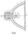
- the lamp/reflector unit comprises a glass reflector body 1 which has a concave reflecting surface 2 with a optical axis 3 and, around the optical axis, a neck 4 with a free-end portion 5.
- the unit has a electric lamp 10 with a lamp vessel 11 which is sealed in a gastight manner and in which a electric element 12, an incandescent body in the Figure, but alternatively a pair of electrodes in a ionizable medium, is arranged and connected to current conductors 13 which issue to the exterior from a seal 14 of the lamp vessel.
- a metal sleeve 20 is fastened around the neck 4 of the reflector body, which sleeve has projections 21 which face away from one another and extend transversely to the optical axis 3.
- the electric lamp 10 is fixed in the neck 4, in the Figure by means of cement 8.
- the current conductors 13 project from the neck 4 through openings 7 and from the sleeve 20 to the exterior, each with a respective free end 15, so as to form contact pins.
- the metal sleeve 20 made of steel in the Figure, has mutually facing projections 22 which enter grooves 6 in the neck 4 of the reflector body 1, while the neck 4 projects with its free-end portion 5 to outside the sleeve 20.
- the reflector body is closed off with a plate 9.
- the mutually facing projections 22 lie farther removed from the free-end portion 5 than do the projections 21 facing away from one another.
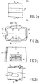
- the sleeve 20 is made from metal plating and the mutually facing projections 22 are immediately adjacent to the projections 21 facing away from one another. Retention means of a lampholder as a result have extra large contact surfaces (see also Fig. 2d).
- the sleeve 20 has a depression 23 which presses against the neck 4 of the reflector body 1, thus rendering possible a greater dimensional tolerance for the neck while a rigid coupling is retained.
- the sleeve 20 has a dovetail closure 24.
- the sleeve is mounted in that it is passed over the neck until the projections 22 snap into the grooves 6.
Landscapes
- Engineering & Computer Science (AREA)
- General Engineering & Computer Science (AREA)
- Fastening Of Light Sources Or Lamp Holders (AREA)
- Common Detailed Techniques For Electron Tubes Or Discharge Tubes (AREA)
- Non-Portable Lighting Devices Or Systems Thereof (AREA)
Claims (4)
- Unité de lampe/réflecteur comportant:un corps de réflecteur en verre (1) muni d'une surface réfléchissante concave (2) présentant un axe optique (3), et d'un col (4) présentant une partie terminale libre (5) entourant l'axe optique;une lampe électrique (10) présentant un récipient de lampe (11) qui est scellé d'une manière étanche au gaz et dans lequel un élément électrique (12) est disposé et relié à des conducteurs de courant (13) qui sortent d'un scellement (14) du récipient de lampe en s'étendant vers l'extérieur;un manchon métallique (20) fixé autour du col (4) du corps de réflecteur (1), ledit manchon présente des saillies (21) qui sont situées l'une à l'opposé de l'autre et qui s'étendent transversalement à l'axe optique (3),la lampe électrique (10) étant fixée dans le col (4) et les conducteurs de courant (13) avec une propre extrémité libre (15) chacun sortant du col (4) et du manchon (20) en s'étendant vers l'extérieur de manière à former des broches de contact,caractérisée en ce que le manchon métallique (20) présente des saillies (22) qui sont situées l'une vis-à-vis de l'autre et qui entrent dans des rainures (6) pratiquées dans le col (4) du corps de réflecteur (1), et en ce que la partie terminale libre (5) du col (4) sort du manchon (20) en s'étendant vers l'extérieur le long de l'axe optique (3).
- Unité de lampe/réflecteur selon la revendication 1, caractérisée en ce que les saillies (22) situées l'une vis-à-vis de l'autre sont plus éloignées de la partie terminale libre (5) que les saillies (21) situées l'une à l'opposé de l'autre.
- Unité de lampe/réflecteur selon la revendication 2, caractérisée en ce que le manchon (20) est formé à partir du matériau en tôle métallique et en ce que les saillies (22) situées l'une vis-à-vis de l'autre sont immédiatement contiguës fois aux saillies (21) situées l'une à l'opposé de l'autre.
- Unité de lampe/réflecteur selon la revendication 1, 2 ou 3, caractérisée en ce que le manchon (20) présente une cavité (23) serrant contre le col (4) du corps de réflecteur (1).
Applications Claiming Priority (2)
| Application Number | Priority Date | Filing Date | Title |
|---|---|---|---|
| EP93201951 | 1993-07-05 | ||
| EP93201951 | 1993-07-05 |
Publications (2)
| Publication Number | Publication Date |
|---|---|
| EP0633603A1 EP0633603A1 (fr) | 1995-01-11 |
| EP0633603B1 true EP0633603B1 (fr) | 1997-03-12 |
Family
ID=8213950
Family Applications (1)
| Application Number | Title | Priority Date | Filing Date |
|---|---|---|---|
| EP94201883A Expired - Lifetime EP0633603B1 (fr) | 1993-07-05 | 1994-06-30 | Ensemble lampe/réflecteur |
Country Status (5)
| Country | Link |
|---|---|
| US (1) | US5534742A (fr) |
| EP (1) | EP0633603B1 (fr) |
| JP (1) | JPH0773703A (fr) |
| DE (1) | DE69402000T2 (fr) |
| ES (1) | ES2100626T3 (fr) |
Families Citing this family (6)
| Publication number | Priority date | Publication date | Assignee | Title |
|---|---|---|---|---|
| CN1094651C (zh) * | 1995-08-30 | 2002-11-20 | 皇家菲利浦电子有限公司 | 电反射灯 |
| TW315485B (fr) * | 1995-10-26 | 1997-09-11 | Philips Electronics Nv | |
| EP0802561B1 (fr) * | 1996-04-19 | 2000-07-19 | Patent-Treuhand-Gesellschaft für elektrische Glühlampen mbH | Lampe halogène |
| DE19924355A1 (de) * | 1999-05-27 | 2000-12-07 | Philips Corp Intellectual Pty | Lampe |
| DE10302931A1 (de) * | 2003-01-24 | 2004-07-29 | Patent-Treuhand-Gesellschaft für elektrische Glühlampen mbH | Reflektor und Reflektorlampe |
| US20050111226A1 (en) * | 2003-03-21 | 2005-05-26 | Buschmann Jeffrey P. | Electric lamp with recessed lens |
Family Cites Families (5)
| Publication number | Priority date | Publication date | Assignee | Title |
|---|---|---|---|---|
| DE2932638A1 (de) * | 1979-08-11 | 1981-02-26 | Philips Patentverwaltung | Elektrische lampe mit einem huelsenfoermigen sockel |
| GB2153986B (en) * | 1984-02-11 | 1987-11-18 | Emi Plc Thorn | Improvements in lamps and lamp holders for display lighting |
| EP0367323B1 (fr) * | 1988-10-18 | 1994-07-27 | Koninklijke Philips Electronics N.V. | Unité lampe-réflecteur |
| HU205491B (en) * | 1990-04-28 | 1992-04-28 | Tungsram Reszvenytarsasag | Light source provided with reflector |
| US5367219A (en) * | 1991-11-18 | 1994-11-22 | U.S. Philips Corporation | Electric reflector lamp for use with IEC standard |
-
1994
- 1994-06-30 ES ES94201883T patent/ES2100626T3/es not_active Expired - Lifetime
- 1994-06-30 EP EP94201883A patent/EP0633603B1/fr not_active Expired - Lifetime
- 1994-06-30 DE DE69402000T patent/DE69402000T2/de not_active Expired - Fee Related
- 1994-07-04 JP JP6152190A patent/JPH0773703A/ja active Pending
- 1994-07-05 US US08/270,951 patent/US5534742A/en not_active Expired - Fee Related
Also Published As
| Publication number | Publication date |
|---|---|
| ES2100626T3 (es) | 1997-06-16 |
| US5534742A (en) | 1996-07-09 |
| EP0633603A1 (fr) | 1995-01-11 |
| DE69402000T2 (de) | 1997-08-28 |
| JPH0773703A (ja) | 1995-03-17 |
| DE69402000D1 (de) | 1997-04-17 |
Similar Documents
| Publication | Publication Date | Title |
|---|---|---|
| EP1463908B1 (fr) | Lampe et phare a fixation simple | |
| US5744901A (en) | Electric reflector lamp | |
| JP2000501554A (ja) | 反射型ランプ | |
| EP0633603B1 (fr) | Ensemble lampe/réflecteur | |
| US5436526A (en) | Method of placing a single-capped electric lamp in a lampholder, single-capped electric lamp designed for this purpose, and luminaire provided with the single-capped electric lamp | |
| EP0895647B1 (fr) | Dispositif d'eclairage | |
| WO1996035220A1 (fr) | Lampe electrique a coiffe | |
| CA1122287A (fr) | Prise pour lampe a incandescence sans base | |
| US5367219A (en) | Electric reflector lamp for use with IEC standard | |
| JPH08250248A (ja) | 電球ソケット | |
| EP0397226B1 (fr) | Lampe électrique et support pour cette dernière | |
| JP4488487B2 (ja) | 照明ユニット | |
| US4180758A (en) | Capless electric incandescent lamp | |
| JP3690812B2 (ja) | 反射形電球 | |
| CA1103639A (fr) | Traduction non-disponible | |
| CA2092660A1 (fr) | Luminaire | |
| JPH09199003A (ja) | 片口金形低圧放電ランプ及びそのソケット | |
| EP0367323B1 (fr) | Unité lampe-réflecteur | |
| CA1160195A (fr) | Lampe de mineur | |
| EP0543448B1 (fr) | Lampe électrique à réflecteur | |
| US6525454B2 (en) | Electric lamp | |
| GB2029093A (en) | Attachment of caps to press- sealed lamps | |
| EP0554582B1 (fr) | Lampe électrique | |
| US20030117056A1 (en) | Compact low-pressure discharge lamp | |
| CA1101043A (fr) | Traduction non-disponible |
Legal Events
| Date | Code | Title | Description |
|---|---|---|---|
| PUAI | Public reference made under article 153(3) epc to a published international application that has entered the european phase |
Free format text: ORIGINAL CODE: 0009012 |
|
| AK | Designated contracting states |
Kind code of ref document: A1 Designated state(s): BE DE ES FR GB IT NL |
|
| 17P | Request for examination filed |
Effective date: 19950711 |
|
| GRAG | Despatch of communication of intention to grant |
Free format text: ORIGINAL CODE: EPIDOS AGRA |
|
| 17Q | First examination report despatched |
Effective date: 19960206 |
|
| GRAH | Despatch of communication of intention to grant a patent |
Free format text: ORIGINAL CODE: EPIDOS IGRA |
|
| GRAH | Despatch of communication of intention to grant a patent |
Free format text: ORIGINAL CODE: EPIDOS IGRA |
|
| GRAA | (expected) grant |
Free format text: ORIGINAL CODE: 0009210 |
|
| AK | Designated contracting states |
Kind code of ref document: B1 Designated state(s): BE DE ES FR GB IT NL |
|
| PG25 | Lapsed in a contracting state [announced via postgrant information from national office to epo] |
Ref country code: NL Free format text: LAPSE BECAUSE OF FAILURE TO SUBMIT A TRANSLATION OF THE DESCRIPTION OR TO PAY THE FEE WITHIN THE PRESCRIBED TIME-LIMIT Effective date: 19970312 Ref country code: BE Effective date: 19970312 |
|
| REF | Corresponds to: |
Ref document number: 69402000 Country of ref document: DE Date of ref document: 19970417 |
|
| ITF | It: translation for a ep patent filed | ||
| ET | Fr: translation filed | ||
| REG | Reference to a national code |
Ref country code: ES Ref legal event code: FG2A Ref document number: 2100626 Country of ref document: ES Kind code of ref document: T3 |
|
| NLV1 | Nl: lapsed or annulled due to failure to fulfill the requirements of art. 29p and 29m of the patents act | ||
| PLBE | No opposition filed within time limit |
Free format text: ORIGINAL CODE: 0009261 |
|
| STAA | Information on the status of an ep patent application or granted ep patent |
Free format text: STATUS: NO OPPOSITION FILED WITHIN TIME LIMIT |
|
| 26N | No opposition filed | ||
| REG | Reference to a national code |
Ref country code: FR Ref legal event code: CD |
|
| REG | Reference to a national code |
Ref country code: ES Ref legal event code: PC2A |
|
| PGFP | Annual fee paid to national office [announced via postgrant information from national office to epo] |
Ref country code: ES Payment date: 20000609 Year of fee payment: 7 |
|
| PGFP | Annual fee paid to national office [announced via postgrant information from national office to epo] |
Ref country code: FR Payment date: 20000627 Year of fee payment: 7 |
|
| PGFP | Annual fee paid to national office [announced via postgrant information from national office to epo] |
Ref country code: GB Payment date: 20000630 Year of fee payment: 7 |
|
| PGFP | Annual fee paid to national office [announced via postgrant information from national office to epo] |
Ref country code: DE Payment date: 20000823 Year of fee payment: 7 |
|
| PG25 | Lapsed in a contracting state [announced via postgrant information from national office to epo] |
Ref country code: GB Free format text: LAPSE BECAUSE OF NON-PAYMENT OF DUE FEES Effective date: 20010630 |
|
| PG25 | Lapsed in a contracting state [announced via postgrant information from national office to epo] |
Ref country code: ES Free format text: LAPSE BECAUSE OF NON-PAYMENT OF DUE FEES Effective date: 20010702 |
|
| GBPC | Gb: european patent ceased through non-payment of renewal fee |
Effective date: 20010630 |
|
| PG25 | Lapsed in a contracting state [announced via postgrant information from national office to epo] |
Ref country code: FR Free format text: LAPSE BECAUSE OF NON-PAYMENT OF DUE FEES Effective date: 20020228 |
|
| PG25 | Lapsed in a contracting state [announced via postgrant information from national office to epo] |
Ref country code: DE Free format text: LAPSE BECAUSE OF NON-PAYMENT OF DUE FEES Effective date: 20020403 |
|
| REG | Reference to a national code |
Ref country code: ES Ref legal event code: FD2A Effective date: 20030303 |
|
| PG25 | Lapsed in a contracting state [announced via postgrant information from national office to epo] |
Ref country code: IT Free format text: LAPSE BECAUSE OF NON-PAYMENT OF DUE FEES;WARNING: LAPSES OF ITALIAN PATENTS WITH EFFECTIVE DATE BEFORE 2007 MAY HAVE OCCURRED AT ANY TIME BEFORE 2007. THE CORRECT EFFECTIVE DATE MAY BE DIFFERENT FROM THE ONE RECORDED. Effective date: 20050630 |