EP0633698B1 - Réseau de distribution de télévision par câble avec transmission de signal vidéo à la demande - Google Patents
Réseau de distribution de télévision par câble avec transmission de signal vidéo à la demande Download PDFInfo
- Publication number
- EP0633698B1 EP0633698B1 EP94110415A EP94110415A EP0633698B1 EP 0633698 B1 EP0633698 B1 EP 0633698B1 EP 94110415 A EP94110415 A EP 94110415A EP 94110415 A EP94110415 A EP 94110415A EP 0633698 B1 EP0633698 B1 EP 0633698B1
- Authority
- EP
- European Patent Office
- Prior art keywords
- cable television
- ont
- signal
- video signals
- optical network
- Prior art date
- Legal status (The legal status is an assumption and is not a legal conclusion. Google has not performed a legal analysis and makes no representation as to the accuracy of the status listed.)
- Expired - Lifetime
Links
- 230000008054 signal transmission Effects 0.000 title 1
- 230000003287 optical effect Effects 0.000 claims description 57
- 230000005236 sound signal Effects 0.000 claims description 4
- 239000000284 extract Substances 0.000 claims description 2
- 239000002131 composite material Substances 0.000 claims 7
- 230000005540 biological transmission Effects 0.000 description 10
- 238000000034 method Methods 0.000 description 10
- 239000000203 mixture Substances 0.000 description 7
- 239000013307 optical fiber Substances 0.000 description 7
- 239000000835 fiber Substances 0.000 description 6
- 238000005070 sampling Methods 0.000 description 5
- 238000006243 chemical reaction Methods 0.000 description 2
- 238000005516 engineering process Methods 0.000 description 2
- 238000012546 transfer Methods 0.000 description 2
- 230000006835 compression Effects 0.000 description 1
- 238000007906 compression Methods 0.000 description 1
- 238000013461 design Methods 0.000 description 1
- 230000006870 function Effects 0.000 description 1
- 230000004927 fusion Effects 0.000 description 1
- 230000010363 phase shift Effects 0.000 description 1
- 230000000717 retained effect Effects 0.000 description 1
- 230000011664 signaling Effects 0.000 description 1
- 238000012549 training Methods 0.000 description 1
Images

Classifications
-
- H—ELECTRICITY
- H04—ELECTRIC COMMUNICATION TECHNIQUE
- H04N—PICTORIAL COMMUNICATION, e.g. TELEVISION
- H04N7/00—Television systems
- H04N7/22—Adaptations for optical transmission
-
- H—ELECTRICITY
- H04—ELECTRIC COMMUNICATION TECHNIQUE
- H04J—MULTIPLEX COMMUNICATION
- H04J14/00—Optical multiplex systems
- H04J14/02—Wavelength-division multiplex systems
- H04J14/0227—Operation, administration, maintenance or provisioning [OAMP] of WDM networks, e.g. media access, routing or wavelength allocation
- H04J14/0228—Wavelength allocation for communications one-to-all, e.g. broadcasting wavelengths
- H04J14/023—Wavelength allocation for communications one-to-all, e.g. broadcasting wavelengths in WDM passive optical networks [WDM-PON]
- H04J14/0232—Wavelength allocation for communications one-to-all, e.g. broadcasting wavelengths in WDM passive optical networks [WDM-PON] for downstream transmission
-
- H—ELECTRICITY
- H04—ELECTRIC COMMUNICATION TECHNIQUE
- H04J—MULTIPLEX COMMUNICATION
- H04J14/00—Optical multiplex systems
- H04J14/02—Wavelength-division multiplex systems
- H04J14/0227—Operation, administration, maintenance or provisioning [OAMP] of WDM networks, e.g. media access, routing or wavelength allocation
- H04J14/0238—Wavelength allocation for communications one-to-many, e.g. multicasting wavelengths
-
- H—ELECTRICITY
- H04—ELECTRIC COMMUNICATION TECHNIQUE
- H04J—MULTIPLEX COMMUNICATION
- H04J14/00—Optical multiplex systems
- H04J14/02—Wavelength-division multiplex systems
- H04J14/0227—Operation, administration, maintenance or provisioning [OAMP] of WDM networks, e.g. media access, routing or wavelength allocation
- H04J14/0241—Wavelength allocation for communications one-to-one, e.g. unicasting wavelengths
- H04J14/0242—Wavelength allocation for communications one-to-one, e.g. unicasting wavelengths in WDM-PON
- H04J14/0245—Wavelength allocation for communications one-to-one, e.g. unicasting wavelengths in WDM-PON for downstream transmission, e.g. optical line terminal [OLT] to ONU
- H04J14/0247—Sharing one wavelength for at least a group of ONUs
-
- H—ELECTRICITY
- H04—ELECTRIC COMMUNICATION TECHNIQUE
- H04J—MULTIPLEX COMMUNICATION
- H04J14/00—Optical multiplex systems
- H04J14/02—Wavelength-division multiplex systems
- H04J14/0226—Fixed carrier allocation, e.g. according to service
-
- H—ELECTRICITY
- H04—ELECTRIC COMMUNICATION TECHNIQUE
- H04J—MULTIPLEX COMMUNICATION
- H04J14/00—Optical multiplex systems
- H04J14/02—Wavelength-division multiplex systems
- H04J14/0278—WDM optical network architectures
- H04J14/0282—WDM tree architectures
-
- H—ELECTRICITY
- H04—ELECTRIC COMMUNICATION TECHNIQUE
- H04J—MULTIPLEX COMMUNICATION
- H04J14/00—Optical multiplex systems
- H04J14/02—Wavelength-division multiplex systems
- H04J14/0298—Wavelength-division multiplex systems with sub-carrier multiplexing [SCM]
Definitions
- the invention relates to a cable television distribution network according to the preamble of claim 1.
- a cable television distribution network with the features mentioned there is known from SPIE Vol. 1817 Optical Communications (1992), pp. 12-22, in particular from Figures 3 and 6.
- the fiber optic distribution network is there is a ring-shaped network.
- the subscriber-specific video signals that to carry out the video retrieval service from the head office (there "Basic Unit "called) to participants in the cable television distribution network must be transmitted there as analog signals.
- the Video signals become subcarriers with different frequencies modulated, the modulated subcarriers (37 pieces) become one Frequency division multiplex signal summarized and this is in Wavelength division multiplexing with the cable television signals to optical Network terminations (called ONUs there).
- Table 1 shows that multiple wavelengths must be used to make a total of 400 Cable television subscribers have the opportunity to offer individual Retrieve video programs. This shows that to achieve the on-demand video service in cable television distribution networks of e.g. over 4000 Participants who need a large number of wavelengths. Out of it there is a great deal of effort for those in the optical network terminations existing wavelength demultiplexer and thus high costs.
- a cable television distribution network which also is set up for the on-demand video service.
- the video signals (and associated audio signals) are not there as analog signals, but as digital signals, the result of a compressing analog-to-digital conversion are transferred.
- frequency division multiplexing is preferred over Given time division multiplexing because the time division multiplexing process in question either not flexible enough or still in the foreseeable future are too expensive.
- the optical transmission takes place with the same optical Carrier used to distribute cable television signals. All Video signals are transmitted to all participants, e.g. 200-400 pieces.
- time-division multiplex signals are optically in the Wavelength division multiplex transmitted.
- These become local Distribution sub-networks formed new time-division multiplex signals, each again both cable television programs and individual subscriber programs Programs included and not shown to customers be transmitted.
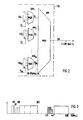
- a cable television center 100 there is an electrical-optical converter 101, which converts the entire signal mixture for transmitting the cable television programs and sound programs, referred to as KTV, into an optical signal with a wavelength ⁇ 1 of 1550 nm.
- This optical signal passes through an optical waveguide distribution network, of which an optical waveguide 102, a beam splitter 103, an optical waveguide 104 leading therefrom to a beam splitter 105 and an optical waveguide 106 leading from the beam splitter 104 to an optical network termination (ONT i ) are shown Number of optical network terminations, which is equal to 64 if the beam splitters have a division factor of 8.
- the optical network termination shown (ONT i ) is representative of all 64, the optical waveguide 104 and the beam splitter 105 is representative of eight each, and fiber-optic amplifiers which are present at different points in the optical waveguide distribution network are omitted in the drawing.
- ONT Optical Network Terminal
- an electrical connection network practically a coaxial cable network, which, as shown, also branches out several times, leads to cable television connections for subscribers, of whom a subscriber 111 symbolically walks through a house is shown.
- the connection network ends at each subscriber at a cable television house transfer point.
- the electrical connection network branches from a line 108 first to a cable distributor 109 to four lines 110, each of which is branched 8 times and branches again on the subscriber 111 onto two lines.
- the cable television mixture provided in the central office is distributed to a large number of subscribers via the optical fiber distribution network and the electrical connection networks, in the example considered here to 4096 subscribers.
- the cable television distribution network described expanded as follows to give participants the opportunity to make use of an on-demand video service.
- the main office 100 are from the provider of the on-demand video service operated memory for video films, e.g. a number of Video cassette recorders (VCR), two of which are shown, for example and designated 120 and 121.
- VCR Video cassette recorders
- a participant says about a telephone connection or one in the cable television distribution network back channel to be set up the desire to watch a specific video see, this will e.g. into one of the video cassette recorders inserted and played.
- the outputs of the video cassette recorder are connected to inputs of a switching device 122 which is controlled according to the request of the participant so that the Broadcast video in a channel towards the subscriber to which he has access.
- the outputs are the switch 122 divided into groups, each Group is assigned to exactly one of the ONT's.
- the one in a group Outputs belonging to outputs represent channels to which the participants who are connected to the ONT to which the group is assigned Have access. Because in that for understanding the invention considered example, the number of ONT's is 64, there are thus, as indicated in the drawing, 64 groups of outputs of the Switch 122. In other words, there are 64 groups of channels in which video signals to participants in the Cable television distribution network are transferable.
- the video signals are transmitted in the Channels digital.
- the bit rate for the transmission of a Video signals in a channel are based on the one hand Available video coding method and on the other hand the quality demands placed on the video signal. How from the publication JOURNAL OF LIGHTWAVE mentioned at the beginning TECHNOLOGY known, there are coding methods that allow one Video signal with good cable television quality with one To transmit bit rate of 6 Mbit / s.
- the Switching device 122 an analog-digital converter 123, in in other words: a video encoder.
- the video signals in the memory from which they can be retrieved are, e.g. in a magnetic or optical Mass storage drive, available in compressed digital form, so that the analog-to-digital converter 123 is not required.
- a multiplexer 124 combines the video signals from the 64 groups, each with 6 channels, to form a time-division multiplex signal, which appears at its output labeled ZM (sometimes signals are also referred to as the lines carrying them), an electrical-optical converter 125 sets it into an optical signal with a wavelength ⁇ 2 of, for example, 1530 nm, and a wavelength multiplexer 126, which is a fiber optic coupler, couples the optical signal with wavelength ⁇ 2 into the same optical fiber 102, which is also the mixture of cable television Signals as an optical signal with the wavelength ⁇ 1 . This ensures that the entirety of digital subscriber-specific video signals is distributed as a time-division multiplex signal in wavelength division multiplex together with the cable television signals to the ONTs.
- the fiber optic amplifiers in the optical fiber distribution network are suitable for both wavelengths.
- the multiplexer 124 has 64 groups of inputs, each with 6 inputs per group. It therefore receives signals from 64 channel groups, which are designated KG 1 to KG 64 in FIG. 2.
- the multiplexer 124 contains a channel multiplexer which combines the video signals from the connected six channels to form a group multiplex signal and in the process inserts additional bits into the resulting group multiplex signal which are used to identify the channel group and to synchronize the respective group multiplex signal again serve demultiplexer.
- the channel multiplexers are designated KM 1 to KM 64 , the outputs carrying the group multiplex signals with G 1 to G 64 and the inputs of the channel multiplexers into which the additional bits are input from sources not shown are designated S 1 to S 64 .
- the group multiplex signal formed by a channel multiplexer has a bit rate of 38.875 MHz when each of the six Channels a bit rate of 6 Mbit / s and the number of inserted additional bits is such that the Net bit rate of 36 Mbit / s and the additional bits Bit rate of 38.875 Mbit / s results.
- the channel multiplexers can be by any time division method work.
- bit rate of 6 Mbit / s per channel you can also other bit repetition frequencies, e.g. 2 Mbit / s are available, including channels with different bit rate frequencies within a channel group.
- bit repetition frequencies e.g. 2 Mbit / s are available, including channels with different bit rate frequencies within a channel group.
- 3 2 Mbit / s channels to one standard 6 Mbit / s channel can be combined in time division multiplexing up to Decoding remain summarized at the participant.
- Essential for the invention is only that a channel multiplexer ones Video signals to a group multiplex signal in time division multiplex summarizes, which are intended for participants who participate in the same ONT are connected. So each channel multiplexer is exactly one assigned to the ONT's.
- time multiplexing device 124 there is also a group multiplexer, the input signals of which are the group multiplex signals G 1 to G 64 , and which combines them to form a time multiplex signal which appears at its output designated ZM.
- the bit rate of the resulting time-division multiplex signal is 2.488 Gbit / s (64x38.875 Mbit / s).
- the 64 input signals can be combined to form a time-division multiplex signal in the group multiplexer GM using any desired time-division multiplex method.
- Bit-by-bit interleaving of the 64 digital input signals G 1 to G 64 is advantageous for the implementation of the invention.
- every 64th bit of the time division multiplex signal generated by the group multiplexer GM is a bit of the same group multiplex signal, for example a bit of G 1 .
- the time-division multiplex signal ZM containing all of the video signals is distributed to all 64 ONTs.
- Each of the ONT's one of which is shown and labeled ONT i , receives and processes the time division multiplex signal as follows: It contains a wavelength demultiplexer 130, which in the simplest case, as indicated in the drawing, is a wavelength-selective fiber fusion coupler. This decouples the optical signal with the wavelength ⁇ 2 from the wavelength multiplex signal and forwards it to the input of an optical-electrical converter 131. The electrical time-division multiplex signal ZM generated at the transmitter end appears.
- regenerator 132 It is regenerated in a regenerator 132 and then reaches a selector 133. This has the task of extracting from the time-division multiplex signal the group multiplex signal which is intended for the group of subscribers connected to the optical network termination and which therefore contains those subscriber-specific video signals intended for these participants.
- the selector 133 is particularly simple if that Time division multiplex signal, as mentioned above, by bitwise Interleaving of the group multiplex signals is formed. He then simply samples the time division multiplex signal with one clock, whose frequency is equal to a 64th of the bit clock of the Time division multiplex signal ZM (2.488 GHz). Every 64th bit of the Time-division multiplex signal belongs to one Group multiplex signal. So the sampling gives a bit stream, which is a group multiplex signal.
- the selector 133 still has to check whether this is due to the Sampled group multiplex signal that for the ONT certain or that is for another ONT. To this For this purpose it checks the one added to the group multiplex signal Identifier. He determines that according to the identifier the removed Group multiplex signal that is intended for the ONT, so it keeps the phase of his sampling clock, he finds in the Group multiplex signal does not have its own identifier, so it sets realizes that this is not for him and postpones the Phase of the sampling clock by one bit period of the time-division multiplex signal, checks the identifier again until it reaches someone Sampling phase has determined that the sampled Group multiplex signal which is intended for the considered ONT. Instead, it is also possible that the selector from the difference between the searched ID and the found ID the necessary phase shift calculated and in a single Step.
- the advantage of bitwise nesting on the sending side and that in optical scanning taking place simple sampling each The 64th bit is that the selector has a clock frequency can work, the low bit rate of 38.875 Mbit / s adapted and not the bit repetition frequency which is higher by a factor of 64 of its input signal.
- a group multiplex signal Gi appears at the output of the selector 133 and is intended for the optical network termination ONT i provided with the same index of its reference symbol. It arrives at a channel demultiplexer, which is the counterpart to one of the channel multiplexers KM i shown in FIG. 2 and which divides the group multiplex signal into its individual video signals, in the example under consideration into the six video signals that appear at its parallel outputs.
- the ONT contains a modulator for each of the six digital video signals, which modulates the video signal onto a subcarrier.
- the six modulators are labeled M 1 to M 6 .
- the subcarriers used in the modulators are in one Frequency range that is not for the service of cable television is occupied or reserved, but within the transferable Frequency band of the electrical connection network is.
- Fig. 3 shows the frequency plan of today and probably also in the future for the service of cable television via coaxial electrical cables is valid.
- the six subcarriers, each one of the six Video signals are modulated at intervals of 6 MHz Frequency range from 411 to 447 MHz.
- the other rectangular areas denote frequency bands of the Cable television, either through sound programs or Cable television programs are or should be occupied.
- FIG. 1 shows a power adder 135, which combines the six subcarriers into a frequency division multiplex signal, which another power adder 136 or a crossover in turn adds to the cable television signal mixture in frequency multiplex, so that finally a signal mixture with frequencies according to FIG. 3 from the output of the power adder 136 , which contains both the analog cable television signals and the digital on-demand video signals, is distributed over the electrical connection network to the subscribers connected to the ONT i under consideration.
- the signal mixture now receives all these participants, but only the Subscriber who has an on-demand video signal contained therein requested, receives the key with which he does this can decrypt the requested signal so that it can use its Video decoder can be decoded.
- a subscriber it is too possible for a subscriber to sign up for the on-demand video service interested in the provider of the service once obtains a fixed, individually assigned key, the for example, is stored on a magnetic card and with the help the magnetic card inserted into its video decoder the situation, the video signal intended only for him decode. It is then not necessary to have a participant every time notify the key when a video signal is sent to it becomes.
- the system according to the invention has the advantage that each subscriber has access to one out of six for the service channels set up, so that the channel selection only at Participants and not already in the optical network termination. This makes it possible for one participant to do the same Can receive video signals on multiple channels.
- the number of channels for the on-demand video service that a group of participants connected to an optical network termination Available can be increased if additional subcarriers, those not used in the service of cable television Frequency ranges are used, or if the coding done with a lower bit rate, so that Frequency spacings between the subcarriers can be smaller.
- the central searches for a free channel in the channel group KG i that corresponds to the optical network termination ONT i the subscriber is connected, is assigned. If, for example, channel 1 of channel group KG i is free, the control center informs the subscriber that his or her desired program can be received on channel 1, and possibly also the time at which transmission is likely to begin.
- This notification takes place, for example, via the telephone network or via a signaling channel to be set up via the cable television distribution network.
- the subscriber has either stored the key that the center uses to encrypt the video signal to be sent on a magnetic card or is also given it by the center.
- the control center then initiates the playback of the desired video signal, if it is in analog form, the analog-to-digital conversion and compression and in any case the encryption with the subscriber-specific key.
- the video signal to be sent then passes via the switching center to the free channel 1 of the channel group KG i . This ensures that the video signal reaches the subscriber who ordered it.
- This transmission then also takes place as for video signals described in digitized form, the participant needs one Audio decoders, in those as described above for video decoders, the key for decryption can be entered.
- Various Audio signals can be combined into a single time-division multiplex Occupy video channel (e.g. with 6Mbit / s) and one Share modulator.
Landscapes
- Engineering & Computer Science (AREA)
- Signal Processing (AREA)
- Computer Networks & Wireless Communication (AREA)
- Multimedia (AREA)
- Two-Way Televisions, Distribution Of Moving Picture Or The Like (AREA)
- Optical Communication System (AREA)
Claims (8)
- Réseau de distribution de télévision par câblecaractérisé en ce que le centre (100) comporte des dispositifs (123 à 126) pour mettre à disposition les signaux vidéo spécifiques aux abonnés comme des signaux numériques et pour regrouper l'ensemble de signaux vidéo numériques, spécifiques aux abonnés, qui sont destinés aux abonnés connectés aux terminaux de réseau optique (ONTi), dans un signal multiplexé dans le temps (ZM) et pour le distribuer de façon optique par multiplexage en longueur d'onde avec l'ensemble composite de signaux de télévision par câble aux terminaux de réseau optique (ONTi), différentes longueurs d'onde étant utilisées pour l'ensemble composite de signaux de télévision par câble et pour le signal multiplexé dans le temps, en ce qu'à chaque terminal de réseau optique (ONTi) il existe des dispositifs (130 à 136, M1 à M6) pour recevoir le signal multiplexé dans le temps (ZM) et en extraire les signaux vidéo (Gi) destinés à des abonnés connectés au terminal de réseau optique (ONTi) et pour ajouter ces signaux vidéo extraits par multiplexage en fréquence au mélange de signaux de télévision par câble qui sont distribués du terminal de réseau optique (ONTi) aux abonnés (111) qui y sont connectés.avec un réseau de distribution à guide d'ondes (101 à 107) allant d'un centre (100) jusqu'à des terminaux de réseau optique (ONTi), - avec respectivement un réseau de connexion électrique allant d'un terminal de réseau optique (ONTi) à un groupe d'abonnés (110) pour distribuer un mélange de signaux de télévision par câble auprès des abonnés,avec des dispositifs (120 à 125) dans le centre (100) pour transmettre en plus des signaux de télévision par câble (KTV) des signaux vidéo spécifiques aux abonnés par multiplexage en longueur d'onde avec l'ensemble composite de signaux de télévision par câble jusqu'aux terminaux de réseau optique (ONTi),
- Réseau de distribution de télévision par câble selon la revendication 1, caractérisé en ce que le centre (100) comprend :pour chaque terminal de réseau optique (ONTi) un multiplexeur de canal (KM1 à KM64) qui regroupe les signaux vidéo (KGi) qui sont destinés à des abonnés (111) connectés au terminal de réseau optique (ONTi) respectif, par multiplexage dans le temps en un signal de multiplexage de groupe (Gi), etun multiplexeur de groupe (GM) qui regroupe les signaux de multiplexage de groupe (GM1 à GM64) dans ledit signal multiplexé dans le temps (ZM) (figure 2).
- Réseau de distribution de télévision par câble selon la revendication 2, caractérisé en ce que le multiplexeur de groupe (GM) entrelace les signaux de multiplexage de groupe (GM1 à GM64) de façon binaire.
- Réseau de distribution de télévision par câble selon la revendication 2, caractérisé en ce que les dispositifs existant à chaque terminal de réseau optique (ONTi) comprennent :un sélecteur (133) qui extrait les signaux vidéo, destinés à des abonnés connectés au terminal de réseau optique (ONTi), du signal multiplexé dans le temps (ZM) comme un signal de multiplexage de groupe (Gi),un démultiplexeur de canal (134) qui décompose le signal de multiplexage de groupe (Gi) en signaux vidéo numériques individuels,des modulateurs (M1 à M6) qui modulent respectivement un signal vidéo sur une sous-porteuse, etdes additionneurs de puissance (135, 136) qui insèrent les sous-porteuses modulées par multiplexage en fréquence dans l'ensemble composite de signaux de télévision par câble.
- Réseau de distribution de télévision par câble selon la revendication 4, caractérisé en ce que les modulateurs (M1 à M6) modulent le signal vidéo numérique respectivement par une modulation d'amplitude sur la sous-porteuse et en ce que les sous-porteuses se trouvent dans un domaine de fréquences (VOD, figure 3) qui n'est pas occupé par l'ensemble composite de signaux de télévision par câble.
- Réseau de distribution de télévision par câble selon l'une quelconque des revendications précédentes, caractérisé en ce qu'il est configuré pour transmettre de façon analogue des signaux audio spécifiques aux abonnés au lieu des signaux vidéo spécifiques aux abonnés ou en plus de ceux-ci.
- Réseau de distribution de télévision par câble selon la revendication 1 ou 2, caractérisé en ce que les dispositifs mettant à disposition les signaux vidéo numériques et/ou les dispositifs (figure 2) formant le signal multiplexé dans le temps sont localisés à distance du centre.
- Réseau de distribution de télévision par câble selon la revendication 1 ou 2, caractérisé en ce que les dispositifs mettant à disposition les signaux vidéo numériques et/ou les dispositifs (figure 2) formant le signal multiplexé dans le temps sont présents dans le centre.
Applications Claiming Priority (2)
| Application Number | Priority Date | Filing Date | Title |
|---|---|---|---|
| DE4323147 | 1993-07-10 | ||
| DE4323147A DE4323147A1 (de) | 1993-07-10 | 1993-07-10 | Kabelfernseh-Verteilnetz mit Abruf-Videosignal-Übertragung |
Publications (3)
| Publication Number | Publication Date |
|---|---|
| EP0633698A2 EP0633698A2 (fr) | 1995-01-11 |
| EP0633698A3 EP0633698A3 (fr) | 1995-06-28 |
| EP0633698B1 true EP0633698B1 (fr) | 1999-09-08 |
Family
ID=6492504
Family Applications (1)
| Application Number | Title | Priority Date | Filing Date |
|---|---|---|---|
| EP94110415A Expired - Lifetime EP0633698B1 (fr) | 1993-07-10 | 1994-07-05 | Réseau de distribution de télévision par câble avec transmission de signal vidéo à la demande |
Country Status (6)
| Country | Link |
|---|---|
| US (1) | US5517232A (fr) |
| EP (1) | EP0633698B1 (fr) |
| AU (1) | AU671913B2 (fr) |
| DE (2) | DE4323147A1 (fr) |
| ES (1) | ES2135513T3 (fr) |
| NZ (1) | NZ260888A (fr) |
Families Citing this family (37)
| Publication number | Priority date | Publication date | Assignee | Title |
|---|---|---|---|---|
| DE4337138C1 (de) * | 1993-10-30 | 1995-03-02 | Ant Nachrichtentech | Rundfunk und Fernsehverteilnetz |
| US5689801A (en) * | 1994-11-14 | 1997-11-18 | Ericsson Inc. | Power monitoring system for a single site, split location trunked radio communication system |
| US5752198A (en) * | 1994-11-14 | 1998-05-12 | Ericsson Inc. | Single site, split location trunked radio communications system |
| DE19505578A1 (de) * | 1995-02-18 | 1996-08-22 | Sel Alcatel Ag | Optisches Übertragungssystem für Kabelfernsehsignale und Video- und Telekommunikationssignale |
| JP3581490B2 (ja) * | 1996-06-25 | 2004-10-27 | ソニー株式会社 | 光送信装置、ディジタル信号伝送装置及びディジタル信号伝送方法 |
| US5822102A (en) * | 1996-07-10 | 1998-10-13 | At&T Corp | Passive optical network employing upconverted 16-cap signals |
| DE19635989A1 (de) * | 1996-09-05 | 1998-03-12 | Sel Alcatel Ag | Sendeeinrichtung zur optischen Übertragung von analogen elektrischen Signalen und digitales Übertragungssystem |
| US6055077A (en) * | 1997-02-25 | 2000-04-25 | Nynex Science & Technology, Inc. | Multimedia distribution system using fiber optic lines |
| DE19643872A1 (de) * | 1996-10-31 | 1998-05-07 | Alsthom Cge Alcatel | Optische Netzabschlußeinheit eines hybriden Glasfaser-Koaxialkabel-Zugangsnetzes |
| DE19701888A1 (de) | 1997-01-21 | 1998-07-23 | Alsthom Cge Alcatel | System zur optischen Übertragung von Informationen |
| US7224896B1 (en) * | 1997-02-25 | 2007-05-29 | Telesector Resources Group, Inc. | Methods and apparatus for generating local oscillation signals |
| US6538781B1 (en) | 1997-02-25 | 2003-03-25 | John Beierle | Multimedia distribution system using fiber optic lines |
| US6151336A (en) * | 1998-02-11 | 2000-11-21 | Sorrento Networks, Inc. | Time division multiplexing expansion subsystem |
| US6400478B1 (en) | 1998-04-02 | 2002-06-04 | Sorrento Networks, Inc. | Wavelength-division-multiplexed optical transmission system with expanded bidirectional transmission capacity over a single fiber |
| US6298103B1 (en) | 1998-06-16 | 2001-10-02 | Sorrento Networks Corporation | Flexible clock and data recovery module for a DWDM optical communication system with multiple clock rates |
| US6437895B1 (en) * | 1999-04-05 | 2002-08-20 | Scientific-Atlanta, Inc. | Digital optical transmitter with compression |
| US6498663B1 (en) | 1999-09-24 | 2002-12-24 | Scientific-Atlanta, Inc. | Methods and systems for detecting optical link performance of an optical link in a hybrid fiber coaxial path |
| US7386236B1 (en) | 1999-09-27 | 2008-06-10 | Alloptic, Inc. | Multiple wavelength TDMA optical network |
| US8745682B1 (en) | 2000-03-13 | 2014-06-03 | Broadcom Corporation | Integrated cable modem and cable television management system |
| US7298975B2 (en) * | 2000-07-13 | 2007-11-20 | L-3 Communications Integrated Systems L.P. | Synchronous collapsed ring architecture for real-time signal switching and distribution |
| WO2002017534A1 (fr) * | 2000-08-25 | 2002-02-28 | Centerpoint Broadband Technologies, Inc. | Systeme terminal a fibres optiques utilisant le multiplexage de sous-porteuses pour le transport de donnees optiques a haute capacite |
| DE10056390A1 (de) * | 2000-11-14 | 2002-05-23 | Daetwyler Ag | Breitbandkabelnetz, Netzwerkinterfacegerät für ein Breitbandkabelnetz und Verfahren zur Übertragung von Daten |
| US7231655B2 (en) * | 2001-08-06 | 2007-06-12 | Time Warner Cable | Technique for reverse transport of data in a hybrid fiber coax cable system |
| WO2003088667A1 (fr) * | 2002-04-12 | 2003-10-23 | Koninklijke Philips Electronics N.V. | Procede de transmission et systeme dote d'une bande de frequence a diffusion unique mappee |
| EP1499061A1 (fr) * | 2003-07-17 | 2005-01-19 | Deutsche Thomson-Brandt Gmbh | Système et méthode de criptage video individuel |
| KR100539928B1 (ko) * | 2003-08-29 | 2005-12-28 | 삼성전자주식회사 | 다파장 광원 및 그를 이용한 파장 분할 다중 시스템 |
| KR20050070566A (ko) * | 2003-12-30 | 2005-07-07 | 삼성전자주식회사 | 다파장 광원과 그를 이용한 파장 분할 다중 시스템 |
| US7103073B2 (en) * | 2004-02-19 | 2006-09-05 | Advanced Fibre Communications, Inc. | Optical line termination, passive optical network, and method and apparatus for performance monitoring |
| US7603036B2 (en) * | 2006-01-06 | 2009-10-13 | Fujitsu Limited | System and method for managing network components in a hybrid passive optical network |
| JP4882614B2 (ja) * | 2006-09-01 | 2012-02-22 | 富士通株式会社 | ビットレート混在光通信方法並びに光加入者装置及び光局側装置 |
| US20080310846A1 (en) * | 2007-06-13 | 2008-12-18 | West Jr Lamar E | Frequency modulated burst mode transmitter |
| US8589993B2 (en) * | 2008-08-29 | 2013-11-19 | At&T Intellectual Property I, L.P. | Distributing on-demand multimedia content |
| US8607272B2 (en) * | 2009-10-29 | 2013-12-10 | At&T Intellectual Property I, Lp | Near-real time internet protocol television |
| US9397898B2 (en) * | 2012-06-29 | 2016-07-19 | Infinera Corporation | Digital link viewer |
| US9351077B1 (en) | 2014-12-11 | 2016-05-24 | L-3 Communications Integrated Systems Lp | Systems and methods for independent and control-isolated audio processing (ICIAP) |
| US10397672B2 (en) * | 2016-06-20 | 2019-08-27 | Cable Television Laboratories, Inc. | Systems and methods for intelligent edge to edge optical system and wavelength provisioning |
| US10200123B2 (en) * | 2016-06-20 | 2019-02-05 | Cable Television Laboratories, Inc. | System and methods for distribution of heterogeneous wavelength multiplexed signals over optical access network |
Family Cites Families (7)
| Publication number | Priority date | Publication date | Assignee | Title |
|---|---|---|---|---|
| JPH0652944B2 (ja) * | 1984-02-23 | 1994-07-06 | 富士通株式会社 | 周波数同期方式 |
| JPH01305698A (ja) * | 1988-06-02 | 1989-12-08 | Nec Corp | 波長・時分割光分配方式 |
| US5136411A (en) * | 1987-12-11 | 1992-08-04 | General Instrument Corporation | Dynamically responsive CATV system with shared fiber optic link |
| US5119188A (en) * | 1988-10-25 | 1992-06-02 | Telaction Corporation | Digital audio-video presentation display system |
| US5442700A (en) * | 1990-09-28 | 1995-08-15 | Ictv, Inc. | Scrambling method |
| JPH04357727A (ja) * | 1991-06-03 | 1992-12-10 | Victor Co Of Japan Ltd | Catv回線による信号送受方式 |
| US5418559A (en) * | 1992-10-23 | 1995-05-23 | At&T Corp. | Multi-channel television converter for conventional and interactive signals |
-
1993
- 1993-07-10 DE DE4323147A patent/DE4323147A1/de not_active Withdrawn
-
1994
- 1994-06-30 NZ NZ260888A patent/NZ260888A/en unknown
- 1994-07-01 AU AU66117/94A patent/AU671913B2/en not_active Ceased
- 1994-07-05 DE DE59408717T patent/DE59408717D1/de not_active Expired - Fee Related
- 1994-07-05 EP EP94110415A patent/EP0633698B1/fr not_active Expired - Lifetime
- 1994-07-05 ES ES94110415T patent/ES2135513T3/es not_active Expired - Lifetime
- 1994-07-07 US US08/271,521 patent/US5517232A/en not_active Expired - Fee Related
Also Published As
| Publication number | Publication date |
|---|---|
| DE59408717D1 (de) | 1999-10-14 |
| EP0633698A3 (fr) | 1995-06-28 |
| AU6611794A (en) | 1995-01-19 |
| DE4323147A1 (de) | 1995-01-12 |
| EP0633698A2 (fr) | 1995-01-11 |
| NZ260888A (en) | 1996-07-26 |
| ES2135513T3 (es) | 1999-11-01 |
| AU671913B2 (en) | 1996-09-12 |
| US5517232A (en) | 1996-05-14 |
Similar Documents
| Publication | Publication Date | Title |
|---|---|---|
| EP0633698B1 (fr) | Réseau de distribution de télévision par câble avec transmission de signal vidéo à la demande | |
| DE69024006T2 (de) | Dynamisch reagierendes Kabelfernsehsystem mit mehrfach genutzter faseroptischer Verbindung. | |
| EP0727889B1 (fr) | Système de transmission optique pour signaux de télévision par câble et pour signaux de vidéo et télécommunication | |
| EP0151454B1 (fr) | Branchement d'abonné dans un système intégré à large bande | |
| DE69012162T2 (de) | Kommunikationsnetzwerk. | |
| DE69010011T2 (de) | Kommunikationssystem. | |
| DE69129893T2 (de) | Optisches Übertragungsnetz mit Frequenzmultiplexierung | |
| EP0193190B1 (fr) | Système optique de transmission d'information dans la zone d'abonnement | |
| DE69719912T2 (de) | Netzwerkgerät und Methode zum Liefern von komprimierten digitalen Videosignalen über Minifaserknotenpunkte | |
| DE2807986A1 (de) | Anlage fuer interaktives kabelfernsehen | |
| DE3913300A1 (de) | Optisches nachrichtenuebertragungssystem fuer den teilnehmeranschlussbereich | |
| EP0817410A2 (fr) | Terminal pour réseau optique, réseau optique et commutateur pour ce réseau | |
| DE4438942A1 (de) | Optisches Nachrichtenübertragungssystem für Kabelfernsehsignale und für teilnehmerindividuelle Signale | |
| EP0386482B1 (fr) | Système de transmission optique pour connexion d'abonné | |
| EP0024618A1 (fr) | Système de télécommunications à large bande | |
| DE3632047C2 (de) | Optisches Nachrichtenübertragungssystem für Schmalband- und Breitband-Nachrichtensignale | |
| DE4226838B4 (de) | Optisches, breitbandiges Nachrichtenübertragungssystem für Kommunikations- und Verteildienste | |
| EP0031014B1 (fr) | Système de télécommunications | |
| EP0881791B1 (fr) | Système de transmission optique d'informations | |
| DE3403206A1 (de) | Lichtwellenleiter-verteilnetz fuer fernseh- und tonprogramme | |
| DE3146468A1 (de) | Multiplexkonzept fuer ein digitales optisches teilnehmeranschlussnetz | |
| DE3422219A1 (de) | Optisches nachrichtenuebertragungssystem im teilnehmeranschlussbereich | |
| EP0854597A2 (fr) | Système de transmission d'informations optiques via plusieurs lignes de transmission optique | |
| DE3242028A1 (de) | Kabelfernsehsystem | |
| DE3129731A1 (de) | Digitales breitband-kommunikationssystem |
Legal Events
| Date | Code | Title | Description |
|---|---|---|---|
| PUAI | Public reference made under article 153(3) epc to a published international application that has entered the european phase |
Free format text: ORIGINAL CODE: 0009012 |
|
| AK | Designated contracting states |
Kind code of ref document: A2 Designated state(s): CH DE ES FR GB IT LI SE |
|
| PUAL | Search report despatched |
Free format text: ORIGINAL CODE: 0009013 |
|
| AK | Designated contracting states |
Kind code of ref document: A3 Designated state(s): CH DE ES FR GB IT LI SE |
|
| 17P | Request for examination filed |
Effective date: 19950818 |
|
| 17Q | First examination report despatched |
Effective date: 19970721 |
|
| GRAG | Despatch of communication of intention to grant |
Free format text: ORIGINAL CODE: EPIDOS AGRA |
|
| GRAG | Despatch of communication of intention to grant |
Free format text: ORIGINAL CODE: EPIDOS AGRA |
|
| GRAH | Despatch of communication of intention to grant a patent |
Free format text: ORIGINAL CODE: EPIDOS IGRA |
|
| GRAH | Despatch of communication of intention to grant a patent |
Free format text: ORIGINAL CODE: EPIDOS IGRA |
|
| GRAA | (expected) grant |
Free format text: ORIGINAL CODE: 0009210 |
|
| RAP1 | Party data changed (applicant data changed or rights of an application transferred) |
Owner name: ALCATEL |
|
| AK | Designated contracting states |
Kind code of ref document: B1 Designated state(s): CH DE ES FR GB IT LI SE |
|
| PG25 | Lapsed in a contracting state [announced via postgrant information from national office to epo] |
Ref country code: SE Free format text: THE PATENT HAS BEEN ANNULLED BY A DECISION OF A NATIONAL AUTHORITY Effective date: 19990908 |
|
| REG | Reference to a national code |
Ref country code: CH Ref legal event code: EP |
|
| ITF | It: translation for a ep patent filed | ||
| REF | Corresponds to: |
Ref document number: 59408717 Country of ref document: DE Date of ref document: 19991014 |
|
| GBT | Gb: translation of ep patent filed (gb section 77(6)(a)/1977) |
Effective date: 19990927 |
|
| REG | Reference to a national code |
Ref country code: ES Ref legal event code: FG2A Ref document number: 2135513 Country of ref document: ES Kind code of ref document: T3 |
|
| ET | Fr: translation filed | ||
| PLBE | No opposition filed within time limit |
Free format text: ORIGINAL CODE: 0009261 |
|
| STAA | Information on the status of an ep patent application or granted ep patent |
Free format text: STATUS: NO OPPOSITION FILED WITHIN TIME LIMIT |
|
| PG25 | Lapsed in a contracting state [announced via postgrant information from national office to epo] |
Ref country code: LI Free format text: LAPSE BECAUSE OF NON-PAYMENT OF DUE FEES Effective date: 20000731 Ref country code: CH Free format text: LAPSE BECAUSE OF NON-PAYMENT OF DUE FEES Effective date: 20000731 |
|
| 26N | No opposition filed | ||
| REG | Reference to a national code |
Ref country code: CH Ref legal event code: PL |
|
| REG | Reference to a national code |
Ref country code: GB Ref legal event code: IF02 |
|
| PGFP | Annual fee paid to national office [announced via postgrant information from national office to epo] |
Ref country code: FR Payment date: 20060714 Year of fee payment: 13 Ref country code: DE Payment date: 20060714 Year of fee payment: 13 |
|
| PGFP | Annual fee paid to national office [announced via postgrant information from national office to epo] |
Ref country code: GB Payment date: 20060720 Year of fee payment: 13 |
|
| PGFP | Annual fee paid to national office [announced via postgrant information from national office to epo] |
Ref country code: ES Payment date: 20060728 Year of fee payment: 13 |
|
| PGFP | Annual fee paid to national office [announced via postgrant information from national office to epo] |
Ref country code: IT Payment date: 20060731 Year of fee payment: 13 |
|
| GBPC | Gb: european patent ceased through non-payment of renewal fee |
Effective date: 20070705 |
|
| PG25 | Lapsed in a contracting state [announced via postgrant information from national office to epo] |
Ref country code: DE Free format text: LAPSE BECAUSE OF NON-PAYMENT OF DUE FEES Effective date: 20080201 |
|
| PG25 | Lapsed in a contracting state [announced via postgrant information from national office to epo] |
Ref country code: GB Free format text: LAPSE BECAUSE OF NON-PAYMENT OF DUE FEES Effective date: 20070705 |
|
| REG | Reference to a national code |
Ref country code: FR Ref legal event code: ST Effective date: 20080331 |
|
| PG25 | Lapsed in a contracting state [announced via postgrant information from national office to epo] |
Ref country code: FR Free format text: LAPSE BECAUSE OF NON-PAYMENT OF DUE FEES Effective date: 20070731 |
|
| REG | Reference to a national code |
Ref country code: ES Ref legal event code: FD2A Effective date: 20070706 |
|
| PG25 | Lapsed in a contracting state [announced via postgrant information from national office to epo] |
Ref country code: ES Free format text: LAPSE BECAUSE OF NON-PAYMENT OF DUE FEES Effective date: 20070706 |
|
| PG25 | Lapsed in a contracting state [announced via postgrant information from national office to epo] |
Ref country code: IT Free format text: LAPSE BECAUSE OF NON-PAYMENT OF DUE FEES Effective date: 20070705 |