EP0633863B1 - Vorrichtung zur förderung von feststoffreichen dickstoffen - Google Patents
Vorrichtung zur förderung von feststoffreichen dickstoffen Download PDFInfo
- Publication number
- EP0633863B1 EP0633863B1 EP93921731A EP93921731A EP0633863B1 EP 0633863 B1 EP0633863 B1 EP 0633863B1 EP 93921731 A EP93921731 A EP 93921731A EP 93921731 A EP93921731 A EP 93921731A EP 0633863 B1 EP0633863 B1 EP 0633863B1
- Authority
- EP
- European Patent Office
- Prior art keywords
- pipe
- cross
- sectional constriction
- lubricant
- conveying pipe
- Prior art date
- Legal status (The legal status is an assumption and is not a legal conclusion. Google has not performed a legal analysis and makes no representation as to the accuracy of the status listed.)
- Expired - Lifetime
Links
Images


Classifications
-
- F—MECHANICAL ENGINEERING; LIGHTING; HEATING; WEAPONS; BLASTING
- F16—ENGINEERING ELEMENTS AND UNITS; GENERAL MEASURES FOR PRODUCING AND MAINTAINING EFFECTIVE FUNCTIONING OF MACHINES OR INSTALLATIONS; THERMAL INSULATION IN GENERAL
- F16L—PIPES; JOINTS OR FITTINGS FOR PIPES; SUPPORTS FOR PIPES, CABLES OR PROTECTIVE TUBING; MEANS FOR THERMAL INSULATION IN GENERAL
- F16L23/00—Flanged joints
- F16L23/04—Flanged joints the flanges being connected by members tensioned in the radial plane
-
- B—PERFORMING OPERATIONS; TRANSPORTING
- B65—CONVEYING; PACKING; STORING; HANDLING THIN OR FILAMENTARY MATERIAL
- B65G—TRANSPORT OR STORAGE DEVICES, e.g. CONVEYORS FOR LOADING OR TIPPING, SHOP CONVEYOR SYSTEMS OR PNEUMATIC TUBE CONVEYORS
- B65G53/00—Conveying materials in bulk through troughs, pipes or tubes by floating the materials or by flow of gas, liquid or foam
- B65G53/34—Details
- B65G53/52—Adaptations of pipes or tubes
- B65G53/523—Wear protection
-
- B—PERFORMING OPERATIONS; TRANSPORTING
- B65—CONVEYING; PACKING; STORING; HANDLING THIN OR FILAMENTARY MATERIAL
- B65G—TRANSPORT OR STORAGE DEVICES, e.g. CONVEYORS FOR LOADING OR TIPPING, SHOP CONVEYOR SYSTEMS OR PNEUMATIC TUBE CONVEYORS
- B65G53/00—Conveying materials in bulk through troughs, pipes or tubes by floating the materials or by flow of gas, liquid or foam
- B65G53/34—Details
- B65G53/58—Devices for accelerating or decelerating flow of the materials; Use of pressure generators
-
- F—MECHANICAL ENGINEERING; LIGHTING; HEATING; WEAPONS; BLASTING
- F16—ENGINEERING ELEMENTS AND UNITS; GENERAL MEASURES FOR PRODUCING AND MAINTAINING EFFECTIVE FUNCTIONING OF MACHINES OR INSTALLATIONS; THERMAL INSULATION IN GENERAL
- F16L—PIPES; JOINTS OR FITTINGS FOR PIPES; SUPPORTS FOR PIPES, CABLES OR PROTECTIVE TUBING; MEANS FOR THERMAL INSULATION IN GENERAL
- F16L57/00—Protection of pipes or objects of similar shape against external or internal damage or wear
-
- F—MECHANICAL ENGINEERING; LIGHTING; HEATING; WEAPONS; BLASTING
- F17—STORING OR DISTRIBUTING GASES OR LIQUIDS
- F17D—PIPE-LINE SYSTEMS; PIPE-LINES
- F17D1/00—Pipe-line systems
- F17D1/08—Pipe-line systems for liquids or viscous products
- F17D1/088—Pipe-line systems for liquids or viscous products for solids or suspensions of solids in liquids, e.g. slurries
-
- F—MECHANICAL ENGINEERING; LIGHTING; HEATING; WEAPONS; BLASTING
- F17—STORING OR DISTRIBUTING GASES OR LIQUIDS
- F17D—PIPE-LINE SYSTEMS; PIPE-LINES
- F17D1/00—Pipe-line systems
- F17D1/08—Pipe-line systems for liquids or viscous products
- F17D1/16—Facilitating the conveyance of liquids or effecting the conveyance of viscous products by modification of their viscosity
-
- F—MECHANICAL ENGINEERING; LIGHTING; HEATING; WEAPONS; BLASTING
- F23—COMBUSTION APPARATUS; COMBUSTION PROCESSES
- F23G—CREMATION FURNACES; CONSUMING WASTE PRODUCTS BY COMBUSTION
- F23G5/00—Incineration of waste; Incinerator constructions; Details, accessories or control therefor
- F23G5/44—Details; Accessories
- F23G5/442—Waste feed arrangements
-
- Y—GENERAL TAGGING OF NEW TECHNOLOGICAL DEVELOPMENTS; GENERAL TAGGING OF CROSS-SECTIONAL TECHNOLOGIES SPANNING OVER SEVERAL SECTIONS OF THE IPC; TECHNICAL SUBJECTS COVERED BY FORMER USPC CROSS-REFERENCE ART COLLECTIONS [XRACs] AND DIGESTS
- Y10—TECHNICAL SUBJECTS COVERED BY FORMER USPC
- Y10T—TECHNICAL SUBJECTS COVERED BY FORMER US CLASSIFICATION
- Y10T137/00—Fluid handling
- Y10T137/0318—Processes
- Y10T137/0391—Affecting flow by the addition of material or energy
-
- Y—GENERAL TAGGING OF NEW TECHNOLOGICAL DEVELOPMENTS; GENERAL TAGGING OF CROSS-SECTIONAL TECHNOLOGIES SPANNING OVER SEVERAL SECTIONS OF THE IPC; TECHNICAL SUBJECTS COVERED BY FORMER USPC CROSS-REFERENCE ART COLLECTIONS [XRACs] AND DIGESTS
- Y10—TECHNICAL SUBJECTS COVERED BY FORMER USPC
- Y10T—TECHNICAL SUBJECTS COVERED BY FORMER US CLASSIFICATION
- Y10T137/00—Fluid handling
- Y10T137/8593—Systems
- Y10T137/87571—Multiple inlet with single outlet
- Y10T137/87652—With means to promote mixing or combining of plural fluids
Definitions
- the invention relates to a device for the conveyance of high-solids thick matter with a conveying tube which can be pressurized with the thick matter and at least one injection point opening into the conveying tube for introducing a lubricant into the area between the pipeline wall and the surface of a thick matter strand forming in the pipeline.
- Devices of this type are used to convey solid-liquid mixtures with a high solid content, such as sewage sludge or clay.
- a high solid content such as sewage sludge or clay.
- Such thick materials have a large internal friction, so that no speed gradient forms when pressed through a conveyor pipe transverse to the direction of propagation. A relative movement essentially only takes place between the surface of the thick material strand and the conveyor line wall, the sliding friction being reduced by the injected lubricant.
- the object of the invention is to improve the known conveying device of the type specified at the outset in such a way that a uniform lubricant layer is maintained along the conveying path with the lowest possible lubricant consumption.
- the invention is based on the finding that a low pressure drop in the delivery line can only be achieved if the thick material strand is transported through the entire delivery pipe largely without contact with the wall. This is the case if a sufficiently thick layer of lubricant can be maintained over the entire conveyor line.
- the delivery pipe has at least one annular cross-sectional constriction arranged downstream at a distance from the injection site. This cross-sectional constriction has the function of a boundary layer fence, which ensures that the lubricant is not unnecessarily through the thick material strand is dragged off.
- the cross-sectional constriction leads to a combing process and to a limitation of the thick material strand to a correspondingly small diameter. Furthermore, a centering of the thick material strand within the conveyor pipe is achieved, which leads to the fact that the lubricant layer remains largely the same thickness over the circumference.
- the inside diameter of the delivery pipe in the area of the cross-sectional constriction is at least 1 mm smaller, preferably 2 to 3 mm smaller than outside this area.
- a preferred embodiment of the invention provides that the cross-sectional constriction is formed by a bead-like or collar-like annular elevation arranged on the inside of the conveyor tube, which can be produced, for example, by an annular welding bead protruding into the interior of the tube or by screwing the tube in or out.
- the cross-sectional constriction can be formed by a collar ring which projects into the interior of the tube and is preferably clamped between two tube flanges.
- a substantially radially penetrating, preferably closable bore for the connection of an injection line for lubricants is arranged in the tube wall, with at least one downstream of the bore from the bore further cross-sectional constriction can be provided.
- the bore is advantageously arranged in the region of the underside of the pipe.
- the annular elevation is expediently produced from wear-resistant material, for example by cladding or the use of a hardened collar ring. The latter is interchangeable in the event of wear.
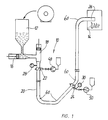
- the conveyor system 10 shown schematically in Fig. 1 is for the conveyance of high-solids sealants, such as determined by partially dewatered sewage sludge, which after intermediate storage in a sludge stack 12 is conveyed via a pipeline 20 for combustion in a fluidized bed furnace 14.
- the conveyor system 10 essentially consists of a compressor pump 16 to which the partially dewatered sewage sludge can be applied, a feed pump 18 which can be fed with the precompressed sewage sludge via the compressor pump 16, a pipeline 20 leading to the fluidized bed furnace 14 and two injection nozzles 22 and 24 arranged in the pipeline 20.
- the injection nozzles 22, 24 can be acted upon with a lubricant via metering pumps 48 and 50, respectively.
- the pressure monitoring of the system takes place via pressure gauges 28 and 30, which are arranged in the vicinity of the injection points 22, 24.
- the pipeline 20 has a plurality of 90 ° or 45 ° pipe bends 60 and opens at the outlet end via a lance 26 into the fluidized bed furnace 14.
- the delivery pipe 20 is composed of several pipe sections 20 ', 20''with the inner diameter D 1, which are connected to each other at pipe flanges 62.
- the pipe flanges 62 are designed as flange rings which are connected to the associated pipe sections 20 ′, 20 ′′ at weld seams 64.
- the flange rings 62 engage with one another in a form-fitting manner with their mutually facing end faces and are axially pressed against one another by means of a clamping ring 66.
- the annular weld 64 with an inside weld bead 68 protrudes about 1 to 2 mm after the inside of the tube and in this way forms a cross-sectional constriction with the inside diameter D2.
- a collar 70 is clamped between the two flange rings 62, which has a 1 to 2 mm smaller inner diameter D2 than the adjacent pipe sections 20 ', 20' 'and in this way forms the desired cross-sectional constriction.
- one of the two flange rings 62 has a smaller inner diameter D2 than the adjacent pipe sections 20 ', 20''and in this way forms the cross-sectional constriction.
- an injection bore 72 which extends through the tube wall and to which a lubricant injection line 76 with a check valve 78 can be connected via a connector 74.
- the injection bore 72 should be arranged on the underside of the delivery pipe.
- a pipe section with injection bore 72 is also expediently installed after each pipe bend 60.
- a continuous thick material strand 82 is conveyed through the conveying tube 20 in the direction of the arrow 80 (FIGS. 2 to 5), the extent of which in the area of the cross-sectional constrictions 68, 70, 62 ', 79 is limited by combing and centered within the conveying tube 20 that an annular gap 84 filled with lubricant 83 remains between its surface and the inside of the tube wall.
- the lubricant is injected into the delivery pipe at the injection points 22, 24.
- the cross-sectional constrictions 68, 70, 62 ', 79 additionally have the function of boundary layer fences, which ensure that there is always sufficient lubricant 83 in the annular gaps 84 which is only carried to a small extent by the moving thick material strand 82.
- the invention relates to a conveyor system for high-solids thick matter with a conveying tube 20 which can be pressurized with the thick matter and at least one injection point 22, 24 opening into the conveying tube 20 for introducing a lubricant 83 into the area 84 between the tube wall and the surface of a thick material strand 82 forming in the conveying tube 20.
- the conveyor tube 20 has at least one annular cross-sectional constriction arranged downstream at a distance from the injection point 22, 24, which constricted by a bead or federal survey 62 'is formed.
- a bore 72 radially penetrating the tube wall can be provided for the connection of an injection line 76 for lubricants, at least one further cross-sectional constriction 79 being arranged downstream at a distance from the injection bore 72.
Landscapes
- Engineering & Computer Science (AREA)
- General Engineering & Computer Science (AREA)
- Mechanical Engineering (AREA)
- Water Supply & Treatment (AREA)
- Health & Medical Sciences (AREA)
- Public Health (AREA)
- Environmental & Geological Engineering (AREA)
- Pusher Or Impeller Conveyors (AREA)
- Pipeline Systems (AREA)
- Air Transport Of Granular Materials (AREA)
- Filtering Of Dispersed Particles In Gases (AREA)
- Yarns And Mechanical Finishing Of Yarns Or Ropes (AREA)
- Structure Of Belt Conveyors (AREA)
Applications Claiming Priority (3)
| Application Number | Priority Date | Filing Date | Title |
|---|---|---|---|
| DE4211138 | 1992-04-03 | ||
| DE4211138A DE4211138A1 (de) | 1992-04-03 | 1992-04-03 | Vorrichtung zur Förderung von feststoffreichen Dickstoffen |
| PCT/EP1993/000251 WO1993020002A1 (de) | 1992-04-03 | 1993-02-04 | Vorrichtung zur förderung von feststoffreichen dickstoffen |
Publications (2)
| Publication Number | Publication Date |
|---|---|
| EP0633863A1 EP0633863A1 (de) | 1995-01-18 |
| EP0633863B1 true EP0633863B1 (de) | 1995-12-06 |
Family
ID=6455934
Family Applications (1)
| Application Number | Title | Priority Date | Filing Date |
|---|---|---|---|
| EP93921731A Expired - Lifetime EP0633863B1 (de) | 1992-04-03 | 1993-02-04 | Vorrichtung zur förderung von feststoffreichen dickstoffen |
Country Status (9)
| Country | Link |
|---|---|
| US (1) | US5605174A (da) |
| EP (1) | EP0633863B1 (da) |
| JP (1) | JP3292476B2 (da) |
| AT (1) | ATE131132T1 (da) |
| CA (1) | CA2133250A1 (da) |
| DE (2) | DE4211138A1 (da) |
| DK (1) | DK0633863T3 (da) |
| ES (1) | ES2081720T3 (da) |
| WO (1) | WO1993020002A1 (da) |
Cited By (1)
| Publication number | Priority date | Publication date | Assignee | Title |
|---|---|---|---|---|
| DE102006016083A1 (de) * | 2006-04-04 | 2007-10-11 | Putzmeister Ag | Kolbenpumpe für Dickstoffe |
Families Citing this family (16)
| Publication number | Priority date | Publication date | Assignee | Title |
|---|---|---|---|---|
| DE29504332U1 (de) * | 1995-03-14 | 1995-05-11 | Esser-Brieden GmbH & Co KG, 59581 Warstein | Rohr zum Feststofftransport |
| DE19514143A1 (de) * | 1995-04-15 | 1996-10-17 | Putzmeister Maschf | Verfahren und Vorrichtung zur Druckförderung von Dickstoffen |
| JPH102452A (ja) * | 1996-06-14 | 1998-01-06 | Smc Corp | 高真空バルブ |
| US5846275A (en) * | 1996-12-31 | 1998-12-08 | Atmi Ecosys Corporation | Clog-resistant entry structure for introducing a particulate solids-containing and/or solids-forming gas stream to a gas processing system |
| US5833888A (en) * | 1996-12-31 | 1998-11-10 | Atmi Ecosys Corporation | Weeping weir gas/liquid interface structure |
| DE19833539A1 (de) * | 1998-07-25 | 2000-01-27 | Putzmeister Ag | Vorrichtung und Verfahren zum Ausbringen von pastösem Fördergut |
| US20070172358A1 (en) * | 2004-02-09 | 2007-07-26 | Paul Scherrer Institut | Protection of surfaces against cavitation erosion |
| JP2009532639A (ja) * | 2006-04-04 | 2009-09-10 | プッツマイスター コンクレーテ プンプス ゲーエムベーハー | 粘性物質のための輸送管 |
| US20080067129A1 (en) * | 2006-09-14 | 2008-03-20 | Weatherford/Lamb, Inc. | Inhibition of paraffin wall deposition in oil lines |
| JP2012512794A (ja) * | 2008-12-18 | 2012-06-07 | プレミアム パテンツ エスディーエヌ. ビーエイチディー | 固体廃棄物を押し進める方法及びシステム |
| US20130126004A1 (en) | 2009-10-26 | 2013-05-23 | Commonwealth Scientific And Industrial Research Organisation | Method, system and device for reducing friction of viscous fluid flowing in aconduit |
| EP2812625A4 (en) | 2012-02-07 | 2016-01-13 | Commw Scient Ind Res Org | REDUCTION OF THE FRICTION OF A VISCOUS LIQUID IN A PIPE |
| DE102013012712A1 (de) * | 2013-08-01 | 2015-02-05 | Rwe Innogy Gmbh | Flanschverbindung an einer Offshore-Struktur |
| DE102015111455A1 (de) * | 2015-07-15 | 2017-01-19 | Esser-Werke Gmbh & Co. Kg | Verfahren zur Herstellung eines Förderrohres für den Feststofftransport sowie Förderrohr für den Feststofftransport |
| CA2982462C (en) * | 2016-11-08 | 2022-11-22 | Tread Enterprises Ltd. | Decelerating device for air conveyed material |
| DE102021132929A1 (de) * | 2021-12-14 | 2023-06-15 | Purem GmbH | Anschlusselement für eine Abgasanlage einer Brennkraftmaschine |
Family Cites Families (16)
| Publication number | Priority date | Publication date | Assignee | Title |
|---|---|---|---|---|
| GB556707A (en) | 1942-04-07 | 1943-10-18 | Douglas Whitaker | Improvements in or relating to drainage and sewerage systems and pipes therefor |
| US2821205A (en) * | 1952-10-31 | 1958-01-28 | Shell Dev | Method and apparatus for lubricating pipe lines |
| DE1001186B (de) * | 1954-05-31 | 1957-01-17 | Mannesmann Ag | Rohr fuer die pneumatische Foerderung trockener staubfoermiger Gueter |
| US3099993A (en) * | 1960-07-22 | 1963-08-06 | Gordon B Hanson | Method of increasing the efficiency of fluid flow |
| US3414004A (en) * | 1966-05-16 | 1968-12-03 | Pan American Petroleum Corp | Film injector |
| US3601079A (en) * | 1969-10-24 | 1971-08-24 | Gen Electric | Method and apparatus for applying drag-reducing additives |
| US3708207A (en) * | 1971-04-16 | 1973-01-02 | Dynamic Air | High pressure booster valve |
| US3892252A (en) * | 1972-12-18 | 1975-07-01 | Marathon Oil Co | Micellar systems aid in pipelining viscous fluids |
| DE2362557C2 (de) * | 1973-12-17 | 1975-11-13 | Licentia Patent-Verwaltungs-Gmbh, 6000 Frankfurt | Einrichtung zur Herstellung strömungswiderstandsverminderndfar Lösungen |
| US3876259A (en) * | 1974-02-01 | 1975-04-08 | Dynamic Air | Pneumatic booster valves for transporting hot abrasive material |
| CH587171A5 (da) * | 1975-07-09 | 1977-04-29 | Nagel Heinrich | |
| US4510958A (en) * | 1982-05-06 | 1985-04-16 | E. I. Du Pont De Nemours And Company | Apparatus and method for transferring a Bingham solid through a long conduit |
| DE3605723A1 (de) * | 1986-02-22 | 1987-08-27 | Uhde Gmbh | Verfahren und vorrichtung zur foerderung von fest-fluessig-gemischen |
| FR2641263A1 (fr) * | 1988-12-30 | 1990-07-06 | Bp Chimie Sa | Tuyau pour le transport pneumatique de particules de polymere |
| SU1691242A1 (ru) * | 1989-08-08 | 1991-11-15 | Отдел Института горного дела СО АН СССР | Трубопровод дл транспортировки твердеющих закладочных смесей |
| US5361797A (en) * | 1993-06-01 | 1994-11-08 | Schwing America, Inc. | Sludge pipeline lubrication system |
-
1992
- 1992-04-03 DE DE4211138A patent/DE4211138A1/de not_active Withdrawn
-
1993
- 1993-02-04 ES ES93921731T patent/ES2081720T3/es not_active Expired - Lifetime
- 1993-02-04 EP EP93921731A patent/EP0633863B1/de not_active Expired - Lifetime
- 1993-02-04 WO PCT/EP1993/000251 patent/WO1993020002A1/de not_active Ceased
- 1993-02-04 US US08/313,292 patent/US5605174A/en not_active Expired - Lifetime
- 1993-02-04 CA CA002133250A patent/CA2133250A1/en not_active Abandoned
- 1993-02-04 DE DE59301116T patent/DE59301116D1/de not_active Expired - Fee Related
- 1993-02-04 AT AT93921731T patent/ATE131132T1/de not_active IP Right Cessation
- 1993-02-04 DK DK93921731.1T patent/DK0633863T3/da active
- 1993-02-04 JP JP51701293A patent/JP3292476B2/ja not_active Expired - Fee Related
Cited By (1)
| Publication number | Priority date | Publication date | Assignee | Title |
|---|---|---|---|---|
| DE102006016083A1 (de) * | 2006-04-04 | 2007-10-11 | Putzmeister Ag | Kolbenpumpe für Dickstoffe |
Also Published As
| Publication number | Publication date |
|---|---|
| JPH07505209A (ja) | 1995-06-08 |
| WO1993020002A1 (de) | 1993-10-14 |
| EP0633863A1 (de) | 1995-01-18 |
| US5605174A (en) | 1997-02-25 |
| ES2081720T3 (es) | 1996-03-16 |
| DE4211138A1 (de) | 1993-10-07 |
| ATE131132T1 (de) | 1995-12-15 |
| DE59301116D1 (de) | 1996-01-18 |
| CA2133250A1 (en) | 1993-10-04 |
| DK0633863T3 (da) | 1996-03-18 |
| JP3292476B2 (ja) | 2002-06-17 |
Similar Documents
| Publication | Publication Date | Title |
|---|---|---|
| EP0633863B1 (de) | Vorrichtung zur förderung von feststoffreichen dickstoffen | |
| DE3821985C1 (da) | ||
| EP1881254B1 (de) | Transportrohr für Dickstoffe | |
| WO2008022616A1 (de) | Förderrohr für den feststofftransport | |
| DE3149932A1 (de) | Bagger-verfahren und -vorrichtung | |
| DE29504332U1 (de) | Rohr zum Feststofftransport | |
| DE60221414T2 (de) | Verfahren zur bohrloch-flüssigkeitsbehandlung und pumpengestänge dafür | |
| DE3145856A1 (de) | Uebertragungsvorrichtung | |
| DE2108591A1 (de) | Einrichtung und Verfahren zur Durchfuh rung des Schildbauweise fur die Errichtung von Tunnels oder Stollen | |
| DE19630039C2 (de) | Rohrbogen | |
| DD252647A5 (de) | Vorrichtung zum verbinden von rohren | |
| DE2646569A1 (de) | Schuettgut-rohrfoerderer | |
| EP1384694B1 (de) | Umlenktopf für den Einbau in pneumatische Förderanlagen | |
| DE102005051767A1 (de) | Förderrohr für den Feststofftransport | |
| DE2757898C2 (de) | Einrichtung zum Fördern von Versatzbergen | |
| DE202005009891U1 (de) | Flexibles Rohr | |
| DE3541674C2 (da) | ||
| DE2545520C3 (de) | Baggerförderleitung | |
| DE3818746C1 (en) | Pipe branch | |
| DE1944686B2 (de) | Vorrichtung zum einbringen eines bohrloches in das erdreich fuer ein fundierungselement und verfahren zum betrieb der vorrichtung | |
| DE3701851A1 (de) | Einrichtung an einer unterirdisch arbeitenden vorrichtung zum vortreiben von rohrleitungen | |
| DE3034992A1 (de) | Schutzvorrichtung an einem brunnen | |
| DE19852869A1 (de) | Pneumatisches Förderrohr und Verfahren zur Fluidisierung eines Förderstroms in einem solchen Förderrohr | |
| CH493769A (de) | Elastischer Dichtungsring | |
| DE10061892C1 (de) | Vorrichtung zur Erhöhung der Feststoffkonzentration in pneumatischen oder hydraulischen Fördersystemen |
Legal Events
| Date | Code | Title | Description |
|---|---|---|---|
| PUAI | Public reference made under article 153(3) epc to a published international application that has entered the european phase |
Free format text: ORIGINAL CODE: 0009012 |
|
| 17P | Request for examination filed |
Effective date: 19940802 |
|
| AK | Designated contracting states |
Kind code of ref document: A1 Designated state(s): AT CH DE DK ES FR GB IT LI NL |
|
| 17Q | First examination report despatched |
Effective date: 19950224 |
|
| GRAA | (expected) grant |
Free format text: ORIGINAL CODE: 0009210 |
|
| AK | Designated contracting states |
Kind code of ref document: B1 Designated state(s): AT CH DE DK ES FR GB IT LI NL |
|
| REF | Corresponds to: |
Ref document number: 131132 Country of ref document: AT Date of ref document: 19951215 Kind code of ref document: T |
|
| PGFP | Annual fee paid to national office [announced via postgrant information from national office to epo] |
Ref country code: DK Payment date: 19960117 Year of fee payment: 4 Ref country code: AT Payment date: 19960117 Year of fee payment: 4 |
|
| REF | Corresponds to: |
Ref document number: 59301116 Country of ref document: DE Date of ref document: 19960118 |
|
| PGFP | Annual fee paid to national office [announced via postgrant information from national office to epo] |
Ref country code: ES Payment date: 19960213 Year of fee payment: 4 |
|
| ET | Fr: translation filed | ||
| GBT | Gb: translation of ep patent filed (gb section 77(6)(a)/1977) |
Effective date: 19960122 |
|
| ITF | It: translation for a ep patent filed | ||
| PGFP | Annual fee paid to national office [announced via postgrant information from national office to epo] |
Ref country code: CH Payment date: 19960223 Year of fee payment: 4 |
|
| REG | Reference to a national code |
Ref country code: ES Ref legal event code: FG2A Ref document number: 2081720 Country of ref document: ES Kind code of ref document: T3 |
|
| REG | Reference to a national code |
Ref country code: DK Ref legal event code: T3 |
|
| PLBE | No opposition filed within time limit |
Free format text: ORIGINAL CODE: 0009261 |
|
| STAA | Information on the status of an ep patent application or granted ep patent |
Free format text: STATUS: NO OPPOSITION FILED WITHIN TIME LIMIT |
|
| 26N | No opposition filed | ||
| PG25 | Lapsed in a contracting state [announced via postgrant information from national office to epo] |
Ref country code: GB Effective date: 19970204 Ref country code: DK Effective date: 19970204 Ref country code: AT Effective date: 19970204 |
|
| REG | Reference to a national code |
Ref country code: DK Ref legal event code: EBP |
|
| PG25 | Lapsed in a contracting state [announced via postgrant information from national office to epo] |
Ref country code: ES Free format text: LAPSE BECAUSE OF NON-PAYMENT OF DUE FEES Effective date: 19970205 |
|
| PG25 | Lapsed in a contracting state [announced via postgrant information from national office to epo] |
Ref country code: LI Effective date: 19970228 Ref country code: CH Effective date: 19970228 |
|
| PG25 | Lapsed in a contracting state [announced via postgrant information from national office to epo] |
Ref country code: NL Effective date: 19970901 |
|
| GBPC | Gb: european patent ceased through non-payment of renewal fee |
Effective date: 19970204 |
|
| REG | Reference to a national code |
Ref country code: CH Ref legal event code: PL |
|
| NLV4 | Nl: lapsed or anulled due to non-payment of the annual fee |
Effective date: 19970901 |
|
| REG | Reference to a national code |
Ref country code: ES Ref legal event code: FD2A Effective date: 19990503 |
|
| PG25 | Lapsed in a contracting state [announced via postgrant information from national office to epo] |
Ref country code: IT Free format text: LAPSE BECAUSE OF NON-PAYMENT OF DUE FEES;WARNING: LAPSES OF ITALIAN PATENTS WITH EFFECTIVE DATE BEFORE 2007 MAY HAVE OCCURRED AT ANY TIME BEFORE 2007. THE CORRECT EFFECTIVE DATE MAY BE DIFFERENT FROM THE ONE RECORDED. Effective date: 20050204 |
|
| PGFP | Annual fee paid to national office [announced via postgrant information from national office to epo] |
Ref country code: FR Payment date: 20060209 Year of fee payment: 14 |
|
| PGFP | Annual fee paid to national office [announced via postgrant information from national office to epo] |
Ref country code: DE Payment date: 20060222 Year of fee payment: 14 |
|
| REG | Reference to a national code |
Ref country code: FR Ref legal event code: ST Effective date: 20071030 |
|
| PG25 | Lapsed in a contracting state [announced via postgrant information from national office to epo] |
Ref country code: DE Free format text: LAPSE BECAUSE OF NON-PAYMENT OF DUE FEES Effective date: 20070901 |
|
| PG25 | Lapsed in a contracting state [announced via postgrant information from national office to epo] |
Ref country code: FR Free format text: LAPSE BECAUSE OF NON-PAYMENT OF DUE FEES Effective date: 20070228 |