EP0634057B1 - Funkgerät mit antennenanordnung - Google Patents
Funkgerät mit antennenanordnung Download PDFInfo
- Publication number
- EP0634057B1 EP0634057B1 EP94909427A EP94909427A EP0634057B1 EP 0634057 B1 EP0634057 B1 EP 0634057B1 EP 94909427 A EP94909427 A EP 94909427A EP 94909427 A EP94909427 A EP 94909427A EP 0634057 B1 EP0634057 B1 EP 0634057B1
- Authority
- EP
- European Patent Office
- Prior art keywords
- radio
- whip
- antenna
- winding
- housing body
- Prior art date
- Legal status (The legal status is an assumption and is not a legal conclusion. Google has not performed a legal analysis and makes no representation as to the accuracy of the status listed.)
- Expired - Lifetime
Links
Images


Classifications
-
- H—ELECTRICITY
- H01—ELECTRIC ELEMENTS
- H01Q—ANTENNAS, i.e. RADIO AERIALS
- H01Q1/00—Details of, or arrangements associated with, antennas
- H01Q1/12—Supports; Mounting means
- H01Q1/22—Supports; Mounting means by structural association with other equipment or articles
- H01Q1/24—Supports; Mounting means by structural association with other equipment or articles with receiving set
-
- H—ELECTRICITY
- H01—ELECTRIC ELEMENTS
- H01Q—ANTENNAS, i.e. RADIO AERIALS
- H01Q1/00—Details of, or arrangements associated with, antennas
- H01Q1/12—Supports; Mounting means
- H01Q1/22—Supports; Mounting means by structural association with other equipment or articles
- H01Q1/24—Supports; Mounting means by structural association with other equipment or articles with receiving set
- H01Q1/241—Supports; Mounting means by structural association with other equipment or articles with receiving set used in mobile communications, e.g. GSM
- H01Q1/242—Supports; Mounting means by structural association with other equipment or articles with receiving set used in mobile communications, e.g. GSM specially adapted for hand-held use
-
- H—ELECTRICITY
- H01—ELECTRIC ELEMENTS
- H01Q—ANTENNAS, i.e. RADIO AERIALS
- H01Q1/00—Details of, or arrangements associated with, antennas
- H01Q1/12—Supports; Mounting means
- H01Q1/22—Supports; Mounting means by structural association with other equipment or articles
- H01Q1/24—Supports; Mounting means by structural association with other equipment or articles with receiving set
- H01Q1/241—Supports; Mounting means by structural association with other equipment or articles with receiving set used in mobile communications, e.g. GSM
- H01Q1/242—Supports; Mounting means by structural association with other equipment or articles with receiving set used in mobile communications, e.g. GSM specially adapted for hand-held use
- H01Q1/243—Supports; Mounting means by structural association with other equipment or articles with receiving set used in mobile communications, e.g. GSM specially adapted for hand-held use with built-in antennas
- H01Q1/244—Supports; Mounting means by structural association with other equipment or articles with receiving set used in mobile communications, e.g. GSM specially adapted for hand-held use with built-in antennas extendable from a housing along a given path
-
- H—ELECTRICITY
- H01—ELECTRIC ELEMENTS
- H01Q—ANTENNAS, i.e. RADIO AERIALS
- H01Q1/00—Details of, or arrangements associated with, antennas
- H01Q1/36—Structural form of radiating elements, e.g. cone, spiral, umbrella; Particular materials used therewith
- H01Q1/362—Structural form of radiating elements, e.g. cone, spiral, umbrella; Particular materials used therewith for broadside radiating helical antennas
Definitions
- the present invention relates generally to antenna assemblies and, more particularly, to an antenna assembly, for a portable radio operable to transmit or receive, or both transmit and receive, high-frequency, modulated signals.
- a communication system is comprised, at a minimum, of a transmitter and a receiver interconnected by a transmission channel.
- a communication signal is transmitted upon the transmission channel, thereafter to be received by the receiver.
- a radio communication system is a communication system in which the transmission channel comprises a radio frequency channel wherein the radio frequency channel is defined by a range of frequencies of the electromagnetic frequency spectrum.
- a transmitter operative in a radio communication system converts the communication signal to be transmitted into a form suitable for transmission thereof upon the radio frequency channel.
- Conversion of the communication signal into the form suitable for the transmission thereof upon the radio frequency channel is effectuated by a process referred to as modulation.
- the communication signal is impressed upon an electromagnetic wave.
- the electromagnetic wave is commonly referred to as a "carrier signal.”
- the resultant signal, once modulated by the communication signal is referred to as a modulated carrier signal, or, more simply, a modulated signal.
- the transmitter indudes circuitry operative to perform such a modulation process.
- radio communication systems are widely utilized to effectuate communication between a transmitter and a remotely-positioned receiver.
- the receiver of the radio communication system which receives the modulated carrier signal contains circuitry analogous to, but operative in a manner reverse with that of, the circuitry of the transmitter and is operative to perform a process referred to as demodulation.
- Numerous modulated carrier signals may be simultaneously transmitted as long as the signals are transmitted along differing radio frequency channels defined upon the electromagnetic frequency spectrum. Regulatory bodies have divided portions of the electromagnetic frequency spectrum into frequency bands and have regulated transmission of the modulated signals upon various ones of the frequency bands. The frequency bands are further divided into channels, and such channels form the radio frequency channels of a radio communication system. It is of course to be understood that separate channels may be defined over a single range of frequencies when signals are transmitted in a discontinuous manner, such as, e.g., in a time division multiple access (TDMA) communication scheme.
- TDMA time division multiple access
- a two-way radio communication system is a radio communication system, similar to the radio communication system above-described, but which permits both transmission of a modulated signal from a location and reception at such location of a modulated signal.
- Each location of such a two-way communication system contains both a transmitter and a receiver.
- the transmitter and the receiver positioned together at the single location typically comprise a unit referred to as a radio transceiver or, more simply, a transceiver.
- a cellular communication system is one type of two-way radio communication system and, when operative, communication is permitted with a radio transceiver positioned at any location within a geographic area encompassed by the cellular communication system.
- a cellular communication system is created by positioning a plurality of fixed-site radio transceivers, referred to as base stations, at spaced-apart locations throughout a geographic area.
- the base stations are connected to a conventional, wireline, telephonic network.
- Associated with each base station of the plurality of base stations is a portion of the geographic area encompassed by the cellular communication system. Such portions are referred to as cells.
- Each of the plurality of cells is defined by one of the base stations of the plurality of base stations, and the plurality of cells together define the coverage area of the cellular communication system.
- a radio transceiver referred to in a cellular communication system as a cellular radiotelephone or, more simply, a cellular phone, positioned at any location within the coverage area of the cellular communication system, is able to communicate with a user of the conventional, wireline, telephonic network by way of a base station.
- Modulated signals generated by the radiotelephone are transmitted to a base station, and modulated signals generated by the base station are transmitted to the radiotelephone, thereby to effectuate two-way communication therebetween.
- a signal received by a base station is then transmitted to a desired location of a conventional, wireline network by conventional telephony techniques.
- signals generated at a location of the wireline network are transmitted to a base station by conventional telephony techniques, thereafter to be transmitted to the radiotelephone by the base station.
- radio transceivers operable in cellular communication systems are of dimensions permitting their carriage by a user.
- portable radio transceivers are typically comprised of telephonic handsets which are somewhat analogous in appearance with telephonic handsets of conventional, telephonic apparatus. Namely, such portable transceivers include speaker portions and microphone portions supported in the handsets at spaced distances permitting a user thereof simultaneously to listen to signals transmitted to the transceiver and to generate signals therefrom.
- the transceiver circuitry of a portable transceiver is housed within a transceiver housing body defining the dimensions of the handset and, typically, a single antenna is coupled to such transceiver circuitry.
- the antenna typically extends at a height (i.e., elevation) beyond the transceiver housing body to permit emanation of modulated signals generated during operation of the radio transceiver and to permit reception of modulated signals transmitted thereto.
- the antenna utilized for such a portable radio transceiver is usually designed to form a nondirectional antenna as the user of the portable radio transceiver may position the transceiver in almost any orientation relative to a remote site (in a cellular communication system, such remote site comprises a base station) to which, or from which, modulated signals are transmitted during operation of the transceiver. That is to say, the user of the portable radio transceiver may operate the transceiver when the transceiver is positioned in either a direction directed away or a direction directed towards, or in any direction therebetween, relative to the remote site.
- such antennas are further usually of lengths substantially corresponding to fractional wavelengths of signals to be received by, or transmitted from, the antenna. More particularly, the lengths of such antennas are typically of either one-half or one-quarter wavelengths of such signals.
- a frequency band having frequencies in the upper-hundreds of Megahertz.
- a frequency band comprised of selected radio frequency channels between 800 Megahertz and 900 Megahertz are assigned for use by cellular communications systems.
- the magnitudes of one-half and one-quarter wavelengths of signals transmitted at such frequencies are of lengths of approximately seventeen and nine centimeters, respectively (or approximately seven and three inches, respectively).
- a one-half wavelength antenna of such a length extending beyond a portable radio transceiver housing body also extends a distance beyond the body of a user when the user positions the transceiver for operation thereof.
- shadowing caused by the body of a user does not significantly interfere with transmission or reception of signals by such an antenna which extends beyond the transceiver housing body by a distance approaching --configuring the antenna in the form of the helix somewhat reduces the height at which the antenna so-formed extends beyond the housing body--seventeen centimeters (or seven inches).
- shadowing is used to describe absorption or reflection of modulated signals by an object, usually positioned proximate to an antenna, which prevents desired reception by the antenna or transmission to a remote site, of a modulated signal.
- an antenna here an antenna affixed to a radio transceiver, is positioned proximate to an individual, the individual causes shadowing, the effect of which interferes with signal propagation to and from the antenna.
- Newly-proposed radio communication systems are to be operable at much higher frequencies - namely, in the 1.8 Gigahertz (GHz) range.
- GHz 1.8 Gigahertz
- Such a frequency range is more than twice as great as the just-mentioned 800 - 900 Megahertz range at which existing, cellular communication systems in the United States are operable.
- the lengths of one-half and one-quarter wavelength antennas forming portions of radio transceivers operable at such increased frequencies are of lengths less than one-half of the lengths of corresponding antennas of lengths of one-half and one-quarter wavelengths operable in radio transceivers of the existing, cellular communication systems.
- an antenna of a length of a one-half wavelength of a 1.8 Gigahertz signal is of a length of approximately eight and one third centimeters or three and one quarter inches.
- Antennas of such lengths extending beyond radio transceiver bodies do not extend for distances great enough to avoid significant shadowing effects by the body of a user when operating a radio transceiver to transmit or to receive modulated signals of such frequencies.
- an antenna assembly for a radio transceiver operable to transmit or to receive signals at such increased frequencies which may be positioned to extend beyond the radio transceiver a distance great enough so that shadowing does not significantly affect operation of the radio.
- the present invention accordingly, advantageously provides a nondirectional antenna assembly for a radio having radio circuitry housed within a radio body.
- the present invention further advantageously provides an antenna assembly for a radio which may be positioned to extend therebeyond a distance great enough so that shadowing caused by a user does not significantly affect operation of the radio.
- the present invention yet further provides a radiotelephone having an antenna assembly which may be positioned to extend beyond a transceiver housing body a distance great enough so that shadowing caused by a user thereof does not significantly affect operation of the transceiver.
- the present invention yet further provides a method for positioning a nondirectional antenna beyond a radio housing body having radio circuitry housed therewithin.
- a radio frequency communication device comprising an antenna assembly, and radio circuitry housed within a radio housing body.
- a whip has a proximal side portion and a distal side portion and is positionable to permit extension of at least the distal side portion thereof beyond the radio housing body.
- a first antenna portion is positioned at the distal side portion of the whip and is positionable in unison with the whip.
- a second antenna portion has at least a first side section thereof positioned at the whip and is coupled to the first antenna portion.
- a second side section of the second antenna portion is coupled to the radio circuitry housed within the radio housing body, thereby to couple the first antenna portion with the radio circuitry.
- portable radio transceivers are typically comprised of radio transceiver circuitry housed within a radio transceiver body and an antenna structure, coupled to the radio transceiver circuitry, which extends beyond the radio transceiver body.
- the antenna structures of such radio transceivers are typically of lengths substantially corresponding to fractional wavelengths, such as one-half wavelengths, of the modulated signals to be transmitted and received by the radio transceivers. And, such antenna structures extend to heights beyond the transceiver bodies of the radio transceivers approaching such lengths. (As noted previously, when an antenna is configured in the form of a helix, its height is somewhat less than a when the antenna is configured of a straight length of wire.)
- Radiotelephones comprising the radio transceivers operative in most existing, cellular communication systems are operative to transmit and to receive modulated signals of frequencies between 800 and 900 Megahertz, or thereabouts.
- Antenna structures of lengths of one-half wavelengths of such signals are of lengths of approximately seventeen centimeters (or seven inches).
- the portable radiotelephone When a user of such a radiotelephone having an antenna of a length of the one-half wavelength fully extends the antenna beyond the radiotelephone housing, at least a portion of the antenna is likely to be positioned beyond the user during operation of the radiotelephone. (More particularly, analogous to positioning of a handset of conventional, telephonic apparatus during operation thereof by a user, the portable radiotelephone is positioned alongside the face of the user.) As the antenna extends beyond the radiotelephone by a length approaching seventeen centimeters, shadowing effects caused by the user normally do not significantly impair operation of the radiotelephone.
- Fractional wavelength antennas of lengths of one-half wavelengths of radio transceivers operable at such frequencies are of lengths of approximately eight and one third centimeters (or three and one quarter inches).
- the antenna When a user of a radiotelephone operable at such an increased frequency fully extends a one-half wavelength antenna beyond the housing of the radiotelephone, the antenna extends beyond the housing only by a length approaching the length defined by the fractional (one-half) wavelength of the increased-frequency at which the radiotelephone is operable. Hence, the antenna is significantly more likely to be susceptible to the effects of shadowing caused by a user when the radiotelephone is positioned proximate to the user during operation thereof.
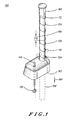
- antenna assembly 100 of a preferred embodiment of the present invention which is operable at the high frequencies of operation (including, for example, the just-mentioned 1.8 Gigahertz frequency) is shown.
- Antenna assembly 100 overcomes the problems associated with existing art antennas when the radiotelephones of which the antennas form portions are constructed to be operable at the increased frequencies.
- Substantial portions of an active portion of antenna assembly 100 may be positioned to extend beyond a radio transceiver housing of a radio transceiver to permit reception and transmission of high-frequency, modulated signals thereat.
- Antenna assembly 100 comprises a nonconductive whip 106 which functions here as a support member and, more generally, as a positioning member.
- Whip 106 is formed of a longitudinally-extending rod member formed of a thermoplastic material having a distal side portion 112 formed of a top portion of whip 106 and proximal side portion 118 formed of a bottom portion of whip 106.
- a simple, monopole antenna formed, typically, of a metallic tube is oftentimes referred to as an "antenna whip," the term whip here shall refer to the nonconductive rod about which helical windings are supported.
- a first antenna portion formed of helical winding 124 is wrapped about distal side portion 112 of whip 106.
- Helical winding 124 in the preferred embodiment, is of an electrical length substantially corresponding to lengths of one-half the wavelengths of signals of frequencies corresponding to the frequencies at which a radio transceiver of which antenna assembly 100 is to form a portion is operable.
- the first antenna portion is formed of the helical winding primarily for production reasons as a wire may be easily wrapped about whip 106.
- a second antenna portion of antenna assembly 100 comprises a first side section and a second side section.
- the first side section of the second antenna portion is formed of helical winding 130.
- Helical winding 130 is wound about proximal side portion 118 of whip 106.
- the first side section of the second antenna portion of assembly 100 is also formed of the helical winding primarily for production reasons. Similar to helical winding 124, in the preferred embodiment, helical winding 130 is also of an electrical length substantially corresponding to lengths of one-half the wavelengths of signals of frequencies corresponding to the frequencies at which a radio transceiver of which assembly 100 is to form a portion is operable.
- the second side section of second antenna portion of antenna assembly 100 is formed of helical winding 136 which is coupled to helical winding 130 by way of electrically-conductive, domed, cap member 142.
- a top end portion of helical winding 136 extends through aperture 148 and is soldered, or otherwise connected, to domed, cap member 142.
- a bottom end portion of helical winding 136 is coupled to transceiver circuitry of the radio transceiver (not shown in the figure) of which antenna assembly 100 forms a portion.
- helical winding 136 is of an electrical length, together with cap member 142 substantially corresponding to lengths of one-quarter the wavelengths of signals of frequencies corresponding to the frequencies at which the transceiver of which antenna assembly 100 is to form a portion is operable. At such a length, helical winding 136 is of a feedpoint impedance of approximately fifty ohms. Such fifty ohm impedance matches the standard, characteristic impedance of most, conventional electronic circuitry.
- Aperture 154 is also formed to extend through domed, cap member 142 and is of a diameter permitting insertion of nonconductive whip 106 therethrough.
- Assembly 100 further indudes sleeve member 160. While, for purposes of illustration, only a portion of sleeve member 160 is shown in the figure, such portion being positioned at distal side portion 112 of whip 106, in the preferred embodiment, sleeve member 160 extends along substantially the entire length of the longitudinally-extending rod member comprising whip 106. Sleeve member 160 is operative to provide a protective covering overtop windings 124 and 130.
- the outside diameter of sleeve member 160 is of a magnitude substantially corresponding to an inside diameter of aperture 154.
- Aperture 154 thereby forms a supportive bushing which permits translation of nonconductive whip 106 in the direction of, and in the direction reverse to that of, arrow 164.
- helical windings 124 and 130 are supported at distal and proximal side portions 112 and 118, respectively, of whip 106, such helical windings, and also sleeve member 160, are similarly translatable in unison with whip 106.
- Whip 106 may also be positioned at locations between fully-retracted and fully-extended antenna positions.
- Helical windings 124 and 130 supported about opposing side portions of nonconductive whip 106 are separated by gap 170, indicated by the arrow shown in the figure. Helical windings 124 and 130 are thereby capacitively coupled theretogether with the magnitude of the capacitive coupling, at least in part, determined by the length of gap 170.
- Helical winding 130 of the first side section of the second antenna portion of antenna assembly 100 and domed cap member 142 of the second side section of the second antenna portion of antenna assembly 100 are thereby also capacitively coupled theretogether as sleeve member 160, which extends along the length of the longitudinally-extending rod comprising whip 106, covers helical winding 130 and thereby physically separates domed cap member 142 and helical winding 130.
- helical winding 124 is electrically coupled to radio circuitry (not shown in the figure) which is connected to the bottom end portion of helical winding 136.
- Helical windings 130 and 136 and domed, cap member 142 thereby together function to couple helical winding 124 to the radio circuitry of the transceiver of which antenna assembly 100 forms a portion, while permitting positioning of helical winding 124 at the distal side portion 112 of whip 106.
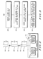
- FIG. 2 is a partial block, partial schematic diagram of antenna assembly 100, shown in isolation in FIG. 1. The view of FIG. 2 further shows antenna assembly 100 in connection with radio transceiver circuitry 176 which is comprised of receiver circuitry portion 178 and transmitter circuitry portion 182.
- Helical windings 124, 130, and 136, and domed, cap member 142 are represented by blocks in the figure. Windings 124 and 130 are tandemly-positioned in the same arrangement as shown in the isolational view of FIG. 1. Helical windings 124 and 130 are capacitively coupled, indicated by capacitor 172 in FIG. 2, due to the physical separation between the windings 124 and 130. Helical winding 130 and domed, cap member 142 are also capacitively coupled theretogether, indicated by capacitor 174 in FIG. 2 due to the physical separation between the two elements 130 and 142 of a magnitude corresponding to the thickness of sleeve member 160.
- helical winding 136 and domed, cap member 142 are electrically connected theretogether, no gap separates winding 136 and cap member 142.
- the bottom end portion of helical winding 136 is electrically connected to the circuitry of radio transceiver 176, here shown to be comprised of receiver circuitry portion 178 and transmitter circuitry portion 182 by way of line 186.
- Windings 130 and 136, and cap member 142 together function to couple remotely-positioned winding 124 to the circuitry of radio transceiver 176.
- helical windings 124 and 130 are, in the preferred embodiment, of lengths substantially corresponding to lengths of one-half the wavelengths of signals of frequencies corresponding to the frequencies at which radio transceiver 176 is operable.
- helical winding 136 together with cap member 142 is of a length substantially corresponding to lengths of one-quarter the wavelengths of the signals of frequencies corresponding to the frequencies at which radio transceiver 176 is operable.
- windings 124 and 130 are of high impedance values, and helical winding 136 is of the feedpoint impedance of approximately fifty ohms (which, again, matches the impedance of radio transceiver 176, typically designed to be of a characteristic impedance of fifty ohms).
- windings 130 and 136, and cap member 142 are operative to couple winding 124 to the circuitry of transceiver 176
- such structure may be substituted, in other embodiments, by other elements.
- such structure may be substituted, in another embodiment, by a shortened, half-wave antenna winding, or a full one-quarter wavelength antenna winding, or a less-than-one-quarter wavelength stub or winding.
- windings 124 and 130 of the lengths of the one-half wavelengths are approximately eight and one third centimeters (three and one quarter inches) in length, respectively.
- winding 136 is of a length of approximately four and one quarter centimeters (one and five eighths inches). Because windings 124 and 130 are positioned in tandem, a top end of helical winding 124 extends dose to seventeen centimeters (six and one half inches) beyond a bottom end portion of helical winding 130.
- Radiotelephone 290 includes an antenna assembly, here referred to by reference numeral 300 as a portion thereof.
- Antenna assembly 300 corresponds to antenna assembly 100 of the preceding figures.
- Radio circuitry corresponding to radio transceiver circuitry 174 of the preceding figure is housed within radiotelephone housing body 304 to be supported therewithin.
- Antenna assembly 300 shown in the extended antenna position, extends beyond a top surface of radiotelephone housing body 304.
- antenna assembly 300 When operative to receive signals of wavelengths corresponding to frequencies of approximately 1.8 Gigahertz, and when antenna assembly 300 is positioned in the extended antenna position, antenna assembly 300 extends beyond a top surface of radiotelephone housing body 304 by a distance of approximately seventeen centimeters (six and one half inches).
- radiotelephone 290 of FIG. 3 is again shown, but, here, radiotelephone 290 is positioned alongside the face of user 395, corresponding to the conventional positioning of the radiotelephone during operation thereof. Positioned as illustrated, user 395 is able simultaneously to listen to signals transmitted to the radiotelephone 290 and also to speak into radiotelephone 290.
- the first antenna portion (comprised of helical winding 124 in the preceding figures) is positioned at a distal side portion of a longitudinally-extending rod forming a portion of antenna assembly 300, which extends a distance approaching almost seventeen centimeters (six and one half inches) beyond a top surface of radiotelephone housing body 304, at least a portion of antenna assembly 300 is likely not to suffer the effects of shadowing caused by user 395. Accordingly, use of antenna assembly 300 permits advantageous use of radiotelephone 290 even when the radiotelephone is operative at frequencies of approximately 1.8 Gigahertz.
- antenna assembly 300 forms a nondirectional antenna which is coupled to transceiver circuitry housed within radiotelephone housing body 304, user 395 may be positioned in any orientation relative to a remote site and signals generated by radiotelephone 290 or transmitted thereto, are transmitted or received by antenna assembly 300.
- Method 500 is operative to position an antenna beyond a radio housing body having radio circuitry housed therewithin while permitting operative engagement of the nondirectional antenna with the radio circuitry.
- a whip having a proximal side portion and a distal side portion is supported at the radio housing body. At least the distal side portion of the whip extends beyond the radio housing body.
- the antenna is supported at the distal side portion of the whip.
- a first side section of an antenna coupler is coupled to the antenna supported at the whip.
- a second side section of the antenna coupler is coupled to the radio circuitry housed within the radio housing body.
- the antenna is thereby coupled to the radio circuitry to couple thereby the antenna in operative engagement with the radio circuitry.
Landscapes
- Engineering & Computer Science (AREA)
- Computer Networks & Wireless Communication (AREA)
- Support Of Aerials (AREA)
- Mobile Radio Communication Systems (AREA)
- Transceivers (AREA)
- Burglar Alarm Systems (AREA)
- Input Circuits Of Receivers And Coupling Of Receivers And Audio Equipment (AREA)
- Details Of Aerials (AREA)
Claims (13)
- Funkfrequenzkommunikationsgerät (290) bestehend aus:einen Gehäusekörper;einer Funkschaltung die im Gehäusekörper untergebracht ist;einer Peitsche (106), die beweglich am Gehäusekörper geführt wird, so daß sich die Peitsche zwischen einer ausgezogenen Position und einer eingezogenen Position bewegt, die Peitsche mit einem Nahende (118), das am Gehäusekörper zu positionieren ist, wenn die Peitsche daran befestigt ist, und
einem Fernende (112), das einen Abstand zum Gehäusekörper hat, wenn die Peitsche daran befestigt ist, das Nahende und das Femende als entgegengesetzte Enden der Peitsche, die Peitsche vom Gehäuse wegweisend, wenn das Nahende daran befestigt ist;einer ersten Antennenwicklung (130), die auf der Peitsche befestigt ist, und die sich vom Nahende in Richtung des Fernendes erstreckt und die bis zu einer Position zwischen Nahende und Fernende reicht, die erste Antennenwicklung mit einem Nahende, um an die Funkschaltung im Gehäusekörper angeschlossen zu werden;einer zweiten Antennenwicklung (124), die auf der Peitsche befestigt ist, und die sich vom Fernende in Richtung des Nahendes erstreckt und die bis zu einer Position zwischen Nahende und Fernende reicht, die erste und die zweite Wicklung mit solchen Längen, daß die erste und die zweite Wicklung kapazitiv gekoppelt aber nicht verbunden sind, wobei die erste und die zweite Wicklung auf der Peitsche bewegt werden und sich mit der Peitsche bewegen und die zweite Wicklung mit der Funkschaltung im Gehäusekörper verbunden ist über die erste Wicklung, wenn die Peitsche ausgezogen ist um Abstand der zweite Wicklung vom Gehäusekörper zu erhalten und um Abschattungseffekte des Benutzers des Funktelefons zu reduzieren. - Kommunikationsgerät nach Anspruch 1, bei dem die erste Antennenwicklung eine Spiralspule enthält.
- Kommunikationsgerät nach Anspruch 2, bei dem die zweite Antennenwicklung eine Spiralspule enthält.
- Kommunikationsgerät nach Anspruch 1, bei dem die erste Antennenwicklung im wesentlichen eine solche Länge hat, die den Längen der halben Wellenlängen von Signalen mit Frequenzen, bei denen die Funkschaltung des Funkgerätes betriebsfähig ist, entspricht.
- Kommunikationsgerät nach Anspruch 1, bei dem die zweite Antennenwicklung im wesentlichen eine solche Länge hat, die den Längen der halben Wellenlängen von Signalen mit Frequenzen, bei denen die Funkschaltung des Funkgerätes betriebsfähig ist, entspricht.
- Kommunikationsgerät nach Anspruch 1, bei dem die erste Antennenwicklung kapazitiv an einen mit der Funkschaltung gekoppelten Leiter im Gehäusekörper gekoppelt ist.
- Kommunikationsgerät nach Anspruch 1, bei dem die erste Antennenwicklung und die zweite Antennenwicklung im wesentlichen die gleiche Länge haben.
- Funktelefon bestehend aus:Gehäuse;Funkschaltung angeordnet im Gehäuse; undAntennenanordnung ausam Gehäuse befestigter einziehbarer Peitsche mit einen nahen Ende, das am Gehäuse angeordnet ist, wenn die Peitsche daran befestigt ist, und mit einem fernen Ende, das mit Abstand zum Gehäuse angeordnet ist, wenn die Peitsche daran befestigt ist, das nahe Ende und das ferne Ende als entgegengesetzte Enden, und die Peitsche aus dem Gehäuse herausragend, wenn das nahe Ende daran angeordnet ist;einer ersten auf der Peitsche angebrachten Antennenwicklung, die sich vom nahen Ende zum fernen Ende erstreckt und die an einer Stelle zwischen dem nahen und fernen Ende ihren Endpunkt hat, die erste Antennenwicklung mit einem nahen Ende zum Anschluß an die Schaltung innerhalb des Gehäuses; undeiner zweiten auf der Peitsche angebrachten Antennenwicklung, die sich vom fernen Ende zum nahen Ende der Peitsche erstreckt, die zweite Antennenwicklung mit einem Endpunkt zwischen den nahen und fernen Ende, die Längen der ersten der zweiten Wicklung solcherart, daß die erste und die zweite Wicklung kapazitiv gekoppelt sind, aber nicht verbunden sind,wobei die erste und die zweite Wicklung auf der Peitsche bewegt werden, um mit der Peitsche eingezogen und ausgezogen werden, die zweite Wicklung gekoppelt an die Schaltung im Gehäuse durch die erste Wicklung, und die zweite Wicklung durch die erste Wicklung im Abstand zum Gehäuse angeordnet, um einen Abschattungseffekt des Nutzers des Funktelefons zu vermindern.
- Funktelefon nach Anspruch 8, bei dem die erste Antennenwicklung eine Spiralspule enthält.
- Funktelefon nach Anspruch 9, bei dem die zweite Antennenwicklung eine Spiralspule enthält.
- Funktelefon nach Anspruch 8, bei dem die erste Antennenwicklung eine Länge hat, die im wesentlichen einer halben Wellenlänge von Signalen von Frequenzen, bei denen die Funkschaltung betriebsfähig ist, entspricht.
- Funktelefon nach Anspruch 8, bei dem die zweite Antennenwicklung eine Länge hat, die im wesentlichen einer halben Wellenlänge von Signalen von Frequenzen, bei denen die Funkschaltung betriebsfähig ist, entspricht.
- Funktelefon nach Anspruch 8, bei dem die erste Wicklung und die zweite Wicklung im wesentlichen die gleiche physische Länge haben.
Applications Claiming Priority (3)
| Application Number | Priority Date | Filing Date | Title |
|---|---|---|---|
| US11016 | 1987-02-05 | ||
| US1101693A | 1993-01-29 | 1993-01-29 | |
| PCT/US1993/012649 WO1994017565A1 (en) | 1993-01-29 | 1993-12-29 | Antenna assembly for radio circuit and method therefor |
Publications (3)
| Publication Number | Publication Date |
|---|---|
| EP0634057A1 EP0634057A1 (de) | 1995-01-18 |
| EP0634057A4 EP0634057A4 (de) | 1995-04-19 |
| EP0634057B1 true EP0634057B1 (de) | 1998-12-02 |
Family
ID=21748490
Family Applications (1)
| Application Number | Title | Priority Date | Filing Date |
|---|---|---|---|
| EP94909427A Expired - Lifetime EP0634057B1 (de) | 1993-01-29 | 1993-12-29 | Funkgerät mit antennenanordnung |
Country Status (10)
| Country | Link |
|---|---|
| US (1) | US5572224A (de) |
| EP (1) | EP0634057B1 (de) |
| JP (1) | JPH07504795A (de) |
| KR (1) | KR950701146A (de) |
| CN (1) | CN1065089C (de) |
| AU (1) | AU661628B2 (de) |
| BR (1) | BR9306081A (de) |
| CA (1) | CA2117561C (de) |
| SG (1) | SG46259A1 (de) |
| WO (1) | WO1994017565A1 (de) |
Families Citing this family (22)
| Publication number | Priority date | Publication date | Assignee | Title |
|---|---|---|---|---|
| US5708445A (en) * | 1993-01-29 | 1998-01-13 | Motorola, Inc. | Antenna assembly for radio circuit and method therefor |
| JP3523670B2 (ja) * | 1993-10-21 | 2004-04-26 | 原田工業株式会社 | 携帯電話機用の挿脱自在形広帯域アンテナ |
| AU691022B2 (en) * | 1994-08-26 | 1998-05-07 | Westinghouse Electric Corporation | Nonsquinting end-fed helical antenna |
| FI97499C (fi) * | 1995-04-07 | 1996-12-27 | Nokia Mobile Phones Ltd | Kaksitoiminen antenni |
| KR100194422B1 (ko) * | 1995-04-27 | 1999-06-15 | 김광호 | 휴대용 무선기기의 안테나 접속장치 |
| JP3166589B2 (ja) * | 1995-12-06 | 2001-05-14 | 株式会社村田製作所 | チップアンテナ |
| US5717408A (en) * | 1995-12-18 | 1998-02-10 | Centurion International, Inc. | Retractable antenna for a cellular telephone |
| SE507746C2 (sv) * | 1996-11-08 | 1998-07-06 | Ericsson Telefon Ab L M | Antennanordning för en mobiltelefon |
| JP3580654B2 (ja) * | 1996-12-04 | 2004-10-27 | 京セラ株式会社 | 共用アンテナおよびこれを用いた携帯無線機 |
| JPH10173421A (ja) * | 1996-12-05 | 1998-06-26 | Harada Ind Co Ltd | 携帯送受信機用棒状アンテナ |
| US5945964A (en) * | 1997-02-19 | 1999-08-31 | Motorola, Inc. | Multi-band antenna structure for a portable radio |
| US5808586A (en) * | 1997-02-19 | 1998-09-15 | Motorola, Inc. | Side-by-side coil-fed antenna for a portable radio |
| SE514568C2 (sv) | 1998-05-18 | 2001-03-12 | Allgon Ab | Antennanordning omfattande matningsmedel och en handburen radiokommunikationsanordning för en sådan antennanordning |
| SE514530C2 (sv) * | 1998-05-18 | 2001-03-12 | Allgon Ab | Antennanordning omfattande kapacitivt kopplade radiotorelement och en handburen radiokommunikationsanordning för en sådan antennanordning |
| US5977928A (en) * | 1998-05-29 | 1999-11-02 | Telefonaktiebolaget Lm Ericsson | High efficiency, multi-band antenna for a radio communication device |
| US6087994A (en) * | 1999-01-19 | 2000-07-11 | Lechter; Robert | Retractable antenna for a cellular phone |
| TWM318202U (en) * | 2007-01-10 | 2007-09-01 | Smart Ant Telecom Co Ltd | Omni-directional high-gain dipole antenna |
| DE102012220615A1 (de) * | 2012-11-13 | 2014-05-15 | BSH Bosch und Siemens Hausgeräte GmbH | Bedienelement für ein Haushaltsgerät |
| US9160392B2 (en) * | 2014-01-23 | 2015-10-13 | Harris Corporation | Rotary knob with integrated antenna |
| CN104362432A (zh) * | 2014-11-13 | 2015-02-18 | 杭州立方控股股份有限公司 | 一种印刷螺旋天线的制作方法 |
| US11404765B2 (en) * | 2020-06-26 | 2022-08-02 | GlaiveRF, Inc. | Retractable phased array for mobile devices |
| US11303012B2 (en) | 2020-08-14 | 2022-04-12 | GlaiveRF, Inc. | Mobile device case with phased array antenna system |
Family Cites Families (14)
| Publication number | Priority date | Publication date | Assignee | Title |
|---|---|---|---|---|
| US4121218A (en) * | 1977-08-03 | 1978-10-17 | Motorola, Inc. | Adjustable antenna arrangement for a portable radio |
| US4229743A (en) * | 1978-09-22 | 1980-10-21 | Shakespeare Company | Multiple band, multiple resonant frequency antenna |
| US4721965A (en) * | 1986-01-22 | 1988-01-26 | General Motors Corporation | AM-FM-cellular telephone multiband antenna for motor vehicle |
| US4725845A (en) * | 1986-03-03 | 1988-02-16 | Motorola, Inc. | Retractable helical antenna |
| US4847629A (en) * | 1988-08-03 | 1989-07-11 | Alliance Research Corporation | Retractable cellular antenna |
| US4868576A (en) * | 1988-11-02 | 1989-09-19 | Motorola, Inc. | Extendable antenna for portable cellular telephones with ground radiator |
| DE3842854A1 (de) * | 1988-12-20 | 1990-06-21 | Bosch Gmbh Robert | Stabantenne fuer den fernsehempfang |
| DE3919884C2 (de) * | 1989-06-19 | 1994-05-19 | Bosch Gmbh Robert | Stabförmige Funkantenne |
| JPH03186001A (ja) * | 1989-12-15 | 1991-08-14 | Matsushita Electric Ind Co Ltd | 空中線装置 |
| US5204687A (en) * | 1990-07-19 | 1993-04-20 | Galtronics Ltd. | Electrical device and electrical transmitter-receiver particularly useful in a ct2 cordless telephone |
| DE4109630A1 (de) * | 1991-03-23 | 1992-09-24 | Bosch Gmbh Robert | Stabfoermiger mehrbereichsstrahler |
| JP2575549B2 (ja) * | 1991-05-07 | 1997-01-29 | 富士通株式会社 | 無線端末装置のアンテナ取付構造 |
| EP0522806B1 (de) * | 1991-07-08 | 1996-11-20 | Nippon Telegraph And Telephone Corporation | Ausfahrbares Antennensystem |
| GB2257835B (en) * | 1991-07-13 | 1995-10-11 | Technophone Ltd | Retractable antenna |
-
1993
- 1993-12-29 JP JP6517028A patent/JPH07504795A/ja active Pending
- 1993-12-29 BR BR9306081A patent/BR9306081A/pt not_active IP Right Cessation
- 1993-12-29 AU AU62273/94A patent/AU661628B2/en not_active Ceased
- 1993-12-29 WO PCT/US1993/012649 patent/WO1994017565A1/en not_active Ceased
- 1993-12-29 CA CA002117561A patent/CA2117561C/en not_active Expired - Fee Related
- 1993-12-29 SG SG1996001657A patent/SG46259A1/en unknown
- 1993-12-29 EP EP94909427A patent/EP0634057B1/de not_active Expired - Lifetime
-
1994
- 1994-01-28 CN CN941011143A patent/CN1065089C/zh not_active Expired - Lifetime
- 1994-09-28 KR KR1019940703374A patent/KR950701146A/ko not_active Ceased
-
1995
- 1995-04-19 US US08/425,694 patent/US5572224A/en not_active Expired - Lifetime
Also Published As
| Publication number | Publication date |
|---|---|
| KR950701146A (ko) | 1995-02-20 |
| AU661628B2 (en) | 1995-07-27 |
| AU6227394A (en) | 1994-08-15 |
| EP0634057A4 (de) | 1995-04-19 |
| CA2117561A1 (en) | 1994-08-04 |
| EP0634057A1 (de) | 1995-01-18 |
| CA2117561C (en) | 1998-04-28 |
| BR9306081A (pt) | 1997-11-18 |
| SG46259A1 (en) | 1998-02-20 |
| JPH07504795A (ja) | 1995-05-25 |
| CN1065089C (zh) | 2001-04-25 |
| CN1096615A (zh) | 1994-12-21 |
| US5572224A (en) | 1996-11-05 |
| WO1994017565A1 (en) | 1994-08-04 |
Similar Documents
| Publication | Publication Date | Title |
|---|---|---|
| US5572224A (en) | Multiple winding whip antenna assembly for radio circuit and method therefor | |
| KR100607097B1 (ko) | 안테나시스템 및 이 안테나시스템을 갖춘 무선통신장치 | |
| US5245350A (en) | Retractable antenna assembly with retraction inactivation | |
| US5923305A (en) | Dual-band helix antenna with parasitic element and associated methods of operation | |
| US6018324A (en) | Omni-directional dipole antenna with a self balancing feed arrangement | |
| CA2063845C (en) | Antenna unit for portable wireless apparatus | |
| US5600341A (en) | Dual function antenna structure and a portable radio having same | |
| JP3287964B2 (ja) | 収縮可能なアンテナ | |
| US5708445A (en) | Antenna assembly for radio circuit and method therefor | |
| JPH0730316A (ja) | 低プロファイルの二目的アンテナ | |
| JP2002500456A (ja) | 伸長給電体を有する引込可能無線電話機アンテナ | |
| US6288681B1 (en) | Dual-band antenna for mobile telecommunication units | |
| EP0718909B1 (de) | Mit einer Last an der Spitze versehene versenkbare Antenne | |
| JPH09186522A (ja) | 二重機能アンテナ構造およびこのアンテナ構造を有する携帯無線装置 | |
| US6008765A (en) | Retractable top load antenna | |
| KR19980702072A (ko) | 휴대폰용 고효율 및 소형 안테나수단 | |
| EP0929913B1 (de) | Antenne für mehrere bänder | |
| US6054959A (en) | Dual resonant antenna | |
| EP0736925B1 (de) | Doppelt wirkende Antenne und Mobiltelefon mit einer solchen Antenne | |
| GB2335312A (en) | An antenna adapted to operate in a plurality of frequency bands | |
| CA2390089A1 (en) | Mobile satellite communication terminal and method for using the same | |
| JPH07326920A (ja) | 携帯トランシーバ用のアンテナアセンブリ | |
| WO2000046873A1 (en) | Wireless phone design for improving radiation performance | |
| JP2002523949A (ja) | スライド式コネクターからなるアンテナ装置 | |
| GB2327813A (en) | A dual resonant antenna |
Legal Events
| Date | Code | Title | Description |
|---|---|---|---|
| PUAI | Public reference made under article 153(3) epc to a published international application that has entered the european phase |
Free format text: ORIGINAL CODE: 0009012 |
|
| 17P | Request for examination filed |
Effective date: 19940817 |
|
| AK | Designated contracting states |
Kind code of ref document: A1 Designated state(s): FR GB IT |
|
| A4 | Supplementary search report drawn up and despatched |
Effective date: 19950301 |
|
| AK | Designated contracting states |
Kind code of ref document: A4 Designated state(s): FR GB IT |
|
| 17Q | First examination report despatched |
Effective date: 19970411 |
|
| GRAG | Despatch of communication of intention to grant |
Free format text: ORIGINAL CODE: EPIDOS AGRA |
|
| GRAG | Despatch of communication of intention to grant |
Free format text: ORIGINAL CODE: EPIDOS AGRA |
|
| GRAH | Despatch of communication of intention to grant a patent |
Free format text: ORIGINAL CODE: EPIDOS IGRA |
|
| GRAH | Despatch of communication of intention to grant a patent |
Free format text: ORIGINAL CODE: EPIDOS IGRA |
|
| GRAA | (expected) grant |
Free format text: ORIGINAL CODE: 0009210 |
|
| AK | Designated contracting states |
Kind code of ref document: B1 Designated state(s): FR GB IT |
|
| PG25 | Lapsed in a contracting state [announced via postgrant information from national office to epo] |
Ref country code: IT Free format text: LAPSE BECAUSE OF FAILURE TO SUBMIT A TRANSLATION OF THE DESCRIPTION OR TO PAY THE FEE WITHIN THE PRE;WARNING: LAPSES OF ITALIAN PATENTS WITH EFFECTIVE DATE BEFORE 2007 MAY HAVE OCCURRED AT ANY TIME BEFORE 2007. THE CORRECT EFFECTIVE DATE MAY BE DIFFERENT FROM THE ONE RECORDED.SCRIBED TIME-LIMIT Effective date: 19981202 |
|
| ET | Fr: translation filed | ||
| PG25 | Lapsed in a contracting state [announced via postgrant information from national office to epo] |
Ref country code: GB Free format text: LAPSE BECAUSE OF NON-PAYMENT OF DUE FEES Effective date: 19990302 |
|
| PLBE | No opposition filed within time limit |
Free format text: ORIGINAL CODE: 0009261 |
|
| STAA | Information on the status of an ep patent application or granted ep patent |
Free format text: STATUS: NO OPPOSITION FILED WITHIN TIME LIMIT |
|
| GBPC | Gb: european patent ceased through non-payment of renewal fee |
Effective date: 19990302 |
|
| PG25 | Lapsed in a contracting state [announced via postgrant information from national office to epo] |
Ref country code: FR Free format text: LAPSE BECAUSE OF NON-PAYMENT OF DUE FEES Effective date: 19991029 |
|
| 26N | No opposition filed | ||
| PGFP | Annual fee paid to national office [announced via postgrant information from national office to epo] |
Ref country code: FR Payment date: 19991202 Year of fee payment: 7 |
|
| REG | Reference to a national code |
Ref country code: FR Ref legal event code: ST |
|
| PG25 | Lapsed in a contracting state [announced via postgrant information from national office to epo] |
Ref country code: FR Free format text: LAPSE BECAUSE OF NON-PAYMENT OF DUE FEES Effective date: 19981231 |