EP0634232B1 - Procédé pour le profilage intérieur de tubes et dispositif pour la réalisation de ce procédé - Google Patents
Procédé pour le profilage intérieur de tubes et dispositif pour la réalisation de ce procédé Download PDFInfo
- Publication number
- EP0634232B1 EP0634232B1 EP94110568A EP94110568A EP0634232B1 EP 0634232 B1 EP0634232 B1 EP 0634232B1 EP 94110568 A EP94110568 A EP 94110568A EP 94110568 A EP94110568 A EP 94110568A EP 0634232 B1 EP0634232 B1 EP 0634232B1
- Authority
- EP
- European Patent Office
- Prior art keywords
- profiling
- tube
- stone
- rolling elements
- rolling
- Prior art date
- Legal status (The legal status is an assumption and is not a legal conclusion. Google has not performed a legal analysis and makes no representation as to the accuracy of the status listed.)
- Expired - Lifetime
Links
Images


Classifications
-
- B—PERFORMING OPERATIONS; TRANSPORTING
- B21—MECHANICAL METAL-WORKING WITHOUT ESSENTIALLY REMOVING MATERIAL; PUNCHING METAL
- B21C—MANUFACTURE OF METAL SHEETS, WIRE, RODS, TUBES, PROFILES OR LIKE SEMI-MANUFACTURED PRODUCTS OTHERWISE THAN BY ROLLING; AUXILIARY OPERATIONS USED IN CONNECTION WITH METAL-WORKING WITHOUT ESSENTIALLY REMOVING MATERIAL
- B21C1/00—Manufacture of metal sheets, wire, rods, tubes or like semi-manufactured products by drawing
- B21C1/16—Metal drawing by machines or apparatus in which the drawing action is effected by means other than drums, e.g. by a longitudinally-moved carriage pulling or pushing the work or stock for making metal sheets, rods or tubes
- B21C1/22—Metal drawing by machines or apparatus in which the drawing action is effected by means other than drums, e.g. by a longitudinally-moved carriage pulling or pushing the work or stock for making metal sheets, rods or tubes specially adapted for making tubular articles
- B21C1/24—Metal drawing by machines or apparatus in which the drawing action is effected by means other than drums, e.g. by a longitudinally-moved carriage pulling or pushing the work or stock for making metal sheets, rods or tubes specially adapted for making tubular articles by means of mandrels
-
- B—PERFORMING OPERATIONS; TRANSPORTING
- B21—MECHANICAL METAL-WORKING WITHOUT ESSENTIALLY REMOVING MATERIAL; PUNCHING METAL
- B21C—MANUFACTURE OF METAL SHEETS, WIRE, RODS, TUBES, PROFILES OR LIKE SEMI-MANUFACTURED PRODUCTS OTHERWISE THAN BY ROLLING; AUXILIARY OPERATIONS USED IN CONNECTION WITH METAL-WORKING WITHOUT ESSENTIALLY REMOVING MATERIAL
- B21C1/00—Manufacture of metal sheets, wire, rods, tubes or like semi-manufactured products by drawing
- B21C1/16—Metal drawing by machines or apparatus in which the drawing action is effected by means other than drums, e.g. by a longitudinally-moved carriage pulling or pushing the work or stock for making metal sheets, rods or tubes
- B21C1/22—Metal drawing by machines or apparatus in which the drawing action is effected by means other than drums, e.g. by a longitudinally-moved carriage pulling or pushing the work or stock for making metal sheets, rods or tubes specially adapted for making tubular articles
-
- B—PERFORMING OPERATIONS; TRANSPORTING
- B21—MECHANICAL METAL-WORKING WITHOUT ESSENTIALLY REMOVING MATERIAL; PUNCHING METAL
- B21C—MANUFACTURE OF METAL SHEETS, WIRE, RODS, TUBES, PROFILES OR LIKE SEMI-MANUFACTURED PRODUCTS OTHERWISE THAN BY ROLLING; AUXILIARY OPERATIONS USED IN CONNECTION WITH METAL-WORKING WITHOUT ESSENTIALLY REMOVING MATERIAL
- B21C37/00—Manufacture of metal sheets, rods, wire, tubes, profiles or like semi-manufactured products, not otherwise provided for; Manufacture of tubes of special shape
- B21C37/06—Manufacture of metal sheets, rods, wire, tubes, profiles or like semi-manufactured products, not otherwise provided for; Manufacture of tubes of special shape of tubes or metal hoses; Combined procedures for making tubes, e.g. for making multi-wall tubes
- B21C37/15—Making tubes of special shape; Making tube fittings
- B21C37/20—Making helical or similar guides in or on tubes without removing material, e.g. by drawing same over mandrels, by pushing same through dies ; Making tubes with angled walls, ribbed tubes or tubes with decorated walls
-
- B—PERFORMING OPERATIONS; TRANSPORTING
- B21—MECHANICAL METAL-WORKING WITHOUT ESSENTIALLY REMOVING MATERIAL; PUNCHING METAL
- B21C—MANUFACTURE OF METAL SHEETS, WIRE, RODS, TUBES, PROFILES OR LIKE SEMI-MANUFACTURED PRODUCTS OTHERWISE THAN BY ROLLING; AUXILIARY OPERATIONS USED IN CONNECTION WITH METAL-WORKING WITHOUT ESSENTIALLY REMOVING MATERIAL
- B21C37/00—Manufacture of metal sheets, rods, wire, tubes, profiles or like semi-manufactured products, not otherwise provided for; Manufacture of tubes of special shape
- B21C37/06—Manufacture of metal sheets, rods, wire, tubes, profiles or like semi-manufactured products, not otherwise provided for; Manufacture of tubes of special shape of tubes or metal hoses; Combined procedures for making tubes, e.g. for making multi-wall tubes
- B21C37/15—Making tubes of special shape; Making tube fittings
- B21C37/20—Making helical or similar guides in or on tubes without removing material, e.g. by drawing same over mandrels, by pushing same through dies ; Making tubes with angled walls, ribbed tubes or tubes with decorated walls
- B21C37/207—Making helical or similar guides in or on tubes without removing material, e.g. by drawing same over mandrels, by pushing same through dies ; Making tubes with angled walls, ribbed tubes or tubes with decorated walls with helical guides
-
- B—PERFORMING OPERATIONS; TRANSPORTING
- B21—MECHANICAL METAL-WORKING WITHOUT ESSENTIALLY REMOVING MATERIAL; PUNCHING METAL
- B21H—MAKING PARTICULAR METAL OBJECTS BY ROLLING, e.g. SCREWS, WHEELS, RINGS, BARRELS, BALLS
- B21H7/00—Making articles not provided for in the preceding groups, e.g. agricultural tools, dinner forks, knives, spoons
- B21H7/18—Making articles not provided for in the preceding groups, e.g. agricultural tools, dinner forks, knives, spoons grooved pins; Rolling grooves, e.g. oil grooves, in articles
- B21H7/187—Rolling helical or rectilinear grooves
Definitions
- the invention relates to a method for the internal profiling of tubes by means of a profiling block arranged coaxially in the interior of the tube, which has a cylindrical envelope surface which faces the inner tube wall in the working position, the surface enclosed by the envelope surface having a surface profile suitable for producing the internal profile, and several Rolling bodies arranged on the outer circumference of the tube and pressing the tube in a work area against the surface profiling of the profiling stone are provided, which in this case carry out a circular movement around the tube while the tube is simultaneously moved axially.
- the invention further relates to a device for carrying out such a method, with a drawing head having a drawing nozzle and a drawing device for transporting the tube in the drawing direction, the drawing nozzle being assigned a drawing mandrel which has a supporting mandrel coaxially arranged and at its free end a profiling stone is arranged and with a roller head with roller bodies, each of which is rotatable about its own axis and additionally about an axis common to the pipe to be machined.
- the object of the invention is to propose a method of the type described at the outset with which it is possible to better utilize the profiling stone.
- a device for carrying out this method is also proposed.
- this task is achieved, starting from a method of the type described in the introduction, in that during the movement mentioned, the profiling stone and rolling elements periodically oscillate axially relative to one another without the working area leaving the area of the surface profiling of the profiling stone.
- the narrow and desirable working area can be moved back and forth on the profiling stone, so that the entire profiling can be fully utilized.
- the relatively small contact forces can be maintained with correspondingly large specific forces. Said relative movement can be achieved both by the corresponding relative movement of all assigned components and by a corresponding axial movement of only the rollers or only the profiling stone, while the respective other component remains at rest relative to the external environment.
- the relative speed between the profiling stone and the rolling body in the opposite direction to the axial movement of the tube is the same, slower or faster than in the opposite direction. This enables adaptation to the processed material qualities and optimization of the working speed.
- a further embodiment of the invention provides that the axial relative movement between the profiling stone and the rolling body is generated by a corresponding axial movement of the rolling body, while the profiling stone maintains its position relative to the environment.
- An alternative to this provides that the axial relative movement between the profiling block and the rolling element is generated by a corresponding axial movement of the profiling block, while the rolling elements maintain their position relative to the surroundings. Both options, as well as a combination of these two options, allow full use of the profiling of the profiling stone.
- the object on which the invention is based starting from a device of the type described in the introduction, is achieved in that the rolling bodies are operated by themselves with a desired stroke and a desired one, or together with the remaining rolling head and / or the drawing nozzle alone or together with the remaining drawing head Speed are axially movable back and forth, the profiling block is rotatable and axially fixed in both directions on the mandrel.
- the already known assemblies of such machines can therefore be retained and it is only necessary to make the rolling head or the drawing head axially movable with a suitable slide, for example, and to provide it with a suitable power drive.
- This can be a hydraulic cylinder or a simple spindle drive, the movement size and the movement speed each via known components such as.
- B. Position encoder or resolver can be monitored. Since traversing drives for machine slides, which include a path control and a speed control and are connected to a suitable machine control, are known in general, this need not be discussed in more detail.
- the drawing nozzle can be designed, for example, as an annular piston and can be actuated via the annular piston.
- rolling elements are mounted hydrostatically. In this way, the diameter of the rolling elements can be kept small with rigid storage and it is still easy to achieve storage without separate bearing elements such. B. rolling elements must be provided. Since the rolling elements and the entire rolling head rotate very quickly (e.g. 15,000 rpm), storage via rolling elements would be problematic.
- the rolling bodies are designed to be adjustable in their radial position within the scope of an intended working area. This enables precise adaptation to the desired roll dimensions.
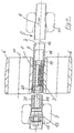
- the basic tool arrangement for carrying out the method according to the invention can be seen most easily from FIG. 5. 5, an inner profile is to be incorporated into the tube 5. Such an internal profile is desirable for. B. in the copper pipes of heat exchanger devices.
- the tube 5 in the drawing nozzle 9 is reduced from the outside diameter D1 to the outside diameter D2 by means of a drawing device, which is not shown in FIG. 5 but is known.
- the wall thickness can be reduced at the same time and a drawing mandrel 13 arranged therein is used in the usual way on the drawing nozzle 9. This arrangement is known and therefore does not require further explanation here.
- the drawing mandrel 13 has a supporting mandrel 14 in a coaxial arrangement with itself and thus also with the tube 5, on the free end of which a profiling block 1 is rotatably arranged.
- a profiling block 1 In the area of this Profiling stones 1 are placed on the outer circumference 4 of the tube 5, rolling elements 6, which are rotatably mounted about an axis 12 common to the components mentioned and about their own axis 11.
- the rolling elements 6 have a working area 7 with which they rest on the outer circumference 4 of the tube 5 and within this working area 7 compress the tube wall and press against the profiling of the profiling stone 1, so that on the inner tube wall 2 one corresponding to the profiling of the profiling stone 1 Profiling is impressed.
- the tube between the roll bodies 6 is reduced from its diameter D2 to the diameter D3.
- the tube 5 is then drawn through a calibration nozzle 16 and reduced to the diameter D4.
- the tube 5 performs an axial movement 8 through the pulling operation, while at the same time the rolling bodies 6 rotate very
- Fig. 4 shows the same basic structure as Fig. 5. In Fig. 4, however, the arrangement and storage of the profiling stone 1 is shown more clearly.
- the support mandrel 14 is rotatably mounted in the mandrel 13 and axially supported in the direction of the axial movement 8 via an axial bearing 17. At the free end, the support mandrel 14 has a stop 18 against which an axial bearing 19 is supported.
- the profiling stone 1 is rotatably arranged on the support mandrel 14, which is also supported on its second end face on an axial bearing 20, which in turn rests with its further plane side on a spacer sleeve 21, which in turn rests with its second end face on the drawing mandrel 13 supports, so that the profiling stone 1 is axially fixed at a certain desired distance from the mandrel 13 and is rotatably supported on the mandrel 14.
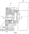
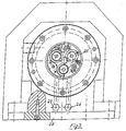
- the roller head 10 is in Fig. 2 in section and in Fig. 3 in an end view. Arrow A shown in Fig. 2. Its arrangement in the overall system is in Fig. 1 shown. A suitable construction for the hydrostatic mounting of the roller bodies 6 and their arrangement in a head which is mounted to be driven by rotation can essentially be left to the person skilled in the art. Therefore, only the essential components of an exemplary embodiment according to FIGS. 2 and 3 are explained here.
- a headstock 22 arranged on a machine bed (not shown in any more detail) carries a spindle 23 which is mounted in a rotationally drivable manner and which is connected to a rotary support 24 which is also rotatably mounted in the roller head 10 and is composed of several individual parts.
- the bearing axes 25 of the rolling elements 6 are arranged distributed over the circumference. In the exemplary embodiment, three bearing axes 25 are provided.
- the necessary fluid with the necessary pressure for the hydrostatic bearing of the rolling elements 6 is supplied to these bearing axles 25 via oil supply lines 26 and 27.
- Such hydrostatic bearings and the necessary fluid inlets and outlets are known in the prior art, so that there is no need to go into this in detail.
- the free ends of the bearing axles 25 are arranged slightly eccentrically with respect to the bearing area for the roller bodies 6, so that rotation of the bearing axles 25 brings about a radial change in position of the roller bodies 6.
- a clamp constructed in any way can then fix the bearing axles 25 in their set position.
- the entire roller head 10 can be mounted on a base 28 and in turn can be fastened to a machine bed (not shown) or, for example, together with the headstock 22 on a slide (not shown) that can be moved back and forth.
- the assembly is therefore both stationary and movable.
- the rolling elements 6 press the tube 5, as already described, against the profiling of the profiling stone 1, so that a corresponding counter-profile is produced on the inner tube wall 2.
- the roller bodies 6, driven by the spindle 23 and the associated rotary support 24, run very quickly around the tube, while the tube simultaneously carries out an axial movement 8 in the direction of drawing.
- roller head 10 and headstock 22 are axially movable on a carriage, they can be moved back and forth with a desired stroke and a desired speed, which also causes the rolling elements 6 to be moved back and forth accordingly, so that they can be used with their working area 7 the entire profiling area of the stationary profiling stone in this case, so that its entire profiling can be exhausted.
- Another possibility to use the entire profiling of the profiling stone is to roll the roller head 10 z. B. stationary and instead move the profiling stone inside the tube 5 accordingly back and forth axially.
- This can be achieved simply by moving the drawing nozzle 9 axially back and forth during the drawing process, as a result of which the drawing mandrel 13 and thus the profiling stone 1 is correspondingly moved back and forth via the supporting mandrel 14.
- the drawing nozzle 9 in the assigned drawing head 15 can be used on its own, e.g. B. in the form of an annular piston, are moved back and forth or, as indicated in the exemplary embodiment and in FIG. 1, can be moved back and forth by means of the entire drawing head 15.
- the pulling head 15 is in this case designed in a customary and known manner, so that its structure need not be described in more detail, but is sufficiently recognizable from the drawing in FIG. 1 as a construction known per se. In this case, however, it is necessary to pull the drawing head 15 on a corresponding slide to arrange, with which to generate the required axial movement, which is indicated in FIG. 1 by the arrow 29. Since the drives for the back and forth movement of the slides are common constructions, there is no need to go into them in detail. The construction of these drives is not the subject of the invention.
- a calibration head 30 with the calibration nozzle 16 is also provided, which reduces the tube 5 to the desired diameter D4 (see FIG. 5) after the profiling process.
- the structure of this calibration head 30 is also known per se, so that there is no need to go into detail about this.
Landscapes
- Engineering & Computer Science (AREA)
- Mechanical Engineering (AREA)
- Life Sciences & Earth Sciences (AREA)
- Agronomy & Crop Science (AREA)
- Metal Extraction Processes (AREA)
- Processing Of Stones Or Stones Resemblance Materials (AREA)
Claims (7)
- Procédé pour le profilage intérieur de tubes (5) au moyen d'une pierre de profilage (1) disposée coaxialement à l'intérieur du tube et présentant une surface enveloppante cylindrique tournée vers la paroi intérieure du tube (2) lorsqu'elle est en en position de travail, selon lequel la surface entourée par la surface enveloppante présente un profilage superficiel (3) convenant à la réalisation du profilage intérieur et selon lequel on prévoit plusieurs éléments de laminage (6) disposés sur le périmètre extérieur (4) du tube (5), lesquels pressent le tube (5) dans une zone de travail (7) contre le profilage superficiel (3) de la pierre de profilage (1) en exécutant un mouvement de rotation autour du tube (5) alors que, simultanément, celui-ci est déplacé axialement, caractérisé en ce que la pierre de profilage (1) et les éléments de laminage (6) oscillent axialement les uns vers les autres de façon périodique sans que, lors de ce mouvement, la zone de travail (7) ne quitte la partie du profilage superficiel (3) de la pierre de profilage (1).
- Procédé selon la revendication 1 caractérisé en ce que, dans le sens contraire au mouvement axial (8) du tube, la vitesse relative entre la pierre de profilage (1) et les éléments de laminage (6) est la même, plus petite ou plus grande que dans le sens inverse.
- Procédé selon l'une des revendications 1 ou 2 caractérisé en ce que le mouvement relatif axial entre la pierre de profilage (1) et les éléments de laminage (6) est produit par un mouvement axial correspondant des éléments de laminage (6) alors que la pierre de profilage (1) maintient sa position par rapport au milieu environnant.
- Procédé selon l'une des revendications 1 ou 2 caractérisé en ce que le mouvement relatif axial entre la pierre de profilage (1) et les éléments de laminage (6) est produit par un mouvement axial correspondant de la pierre de profilage (1) alors que les éléments de laminage (6) maintiennent leur position par rapport au milieu environnant.
- Dispositif pour l'application du procédé selon l'une des revendications 1 à 4, avec une tête d'étirage (15) présentant une filière (9) et un mécanisme d'étirage destiné au transport du tube (5) dans le sens d'étirage (8), un mandrin d'étirage (13) étant prévu pour la filière (9), lequel présente un mandrin de support (14) disposé coaxialement et à l'extrémité libre duquel se trouve une pierre de profilage (1), et avec une tête de laminage (10) pourvue d'éléments de laminage (6), lesquels pivotent chacun sur un palier autour de leur axe propre (11) ainsi qu'autour d'un axe (12) commun avec le tube à usiner (5), caractérisé en ce que les éléments de laminage (6) seuls ou en commun avec le reste de la tête de laminage (10) et/ou la filière (9) seule ou en commun avec le reste de la tête d'étirage (15) sont construits de manière à pouvoir aller et venir axialement de façon périodique alors qu'ils sont actionnés avec la course et à la vitesse voulues, la pierre de profilage (1) étant fixée axialement dans les deux sens et de manière pivotable sur le mandrin de support (14).
- Dispositif selon la revendication 5 caractérisé en ce que les éléments de laminage (6) tournent hydrostatiquement sur paliers.
- Dispositif selon la revendication 5 ou 6 caractérisé en ce que les éléments de laminage (6) sont construits de manière à pouvoir changer de position radiale à l'intérieur d'une zone de travail (7) prévue.
Applications Claiming Priority (2)
| Application Number | Priority Date | Filing Date | Title |
|---|---|---|---|
| DE4323840 | 1993-07-16 | ||
| DE4323840A DE4323840A1 (de) | 1993-07-16 | 1993-07-16 | Verfahren zur Innenprofilierung von Rohren und Einrichtung zur Durchführung des Verfahrens |
Publications (2)
| Publication Number | Publication Date |
|---|---|
| EP0634232A1 EP0634232A1 (fr) | 1995-01-18 |
| EP0634232B1 true EP0634232B1 (fr) | 1997-05-14 |
Family
ID=6492953
Family Applications (1)
| Application Number | Title | Priority Date | Filing Date |
|---|---|---|---|
| EP94110568A Expired - Lifetime EP0634232B1 (fr) | 1993-07-16 | 1994-07-07 | Procédé pour le profilage intérieur de tubes et dispositif pour la réalisation de ce procédé |
Country Status (3)
| Country | Link |
|---|---|
| US (1) | US5524467A (fr) |
| EP (1) | EP0634232B1 (fr) |
| DE (2) | DE4323840A1 (fr) |
Families Citing this family (1)
| Publication number | Priority date | Publication date | Assignee | Title |
|---|---|---|---|---|
| DE10316910B3 (de) * | 2003-04-12 | 2004-09-02 | Sms Meer Gmbh | Verfahren zur Herstellung von Rohren aus metallischem Werkstoff |
Family Cites Families (7)
| Publication number | Priority date | Publication date | Assignee | Title |
|---|---|---|---|---|
| DE542418C (de) * | 1930-06-03 | 1932-01-23 | Ver Stahlwerke Akt Ges | Verfahren zum Auswalzen von Roehren in einem Stopfenwalzwerk |
| JPS56117827A (en) * | 1980-02-19 | 1981-09-16 | Hitachi Cable Ltd | Working device for internally grooved metallic pipe |
| JPS6012132B2 (ja) * | 1980-12-29 | 1985-03-30 | 三菱マテリアル株式会社 | 金属管内外面加工装置 |
| JPH0337770Y2 (fr) * | 1985-03-30 | 1991-08-09 | ||
| JPS6363525A (ja) * | 1986-09-05 | 1988-03-19 | Furukawa Electric Co Ltd:The | 内面溝付管の製造方法 |
| JP2616917B2 (ja) * | 1987-01-24 | 1997-06-04 | 株式会社日立製作所 | ロールシフト圧延機による圧延方法 |
| JP2721253B2 (ja) * | 1989-11-30 | 1998-03-04 | 古河電気工業株式会社 | 伝熱管の製造方法 |
-
1993
- 1993-07-16 DE DE4323840A patent/DE4323840A1/de not_active Ceased
-
1994
- 1994-07-07 EP EP94110568A patent/EP0634232B1/fr not_active Expired - Lifetime
- 1994-07-07 DE DE59402718T patent/DE59402718D1/de not_active Expired - Fee Related
- 1994-07-14 US US08/276,052 patent/US5524467A/en not_active Expired - Fee Related
Also Published As
| Publication number | Publication date |
|---|---|
| DE4323840A1 (de) | 1995-01-19 |
| DE59402718D1 (de) | 1997-06-19 |
| EP0634232A1 (fr) | 1995-01-18 |
| US5524467A (en) | 1996-06-11 |
Similar Documents
| Publication | Publication Date | Title |
|---|---|---|
| EP0353376B1 (fr) | Outil de brunissage | |
| DE3545506C2 (fr) | ||
| DE60036458T2 (de) | Drückwalzvorrichtung | |
| DE2602639A1 (de) | Verfahren und maschine zum bearbeiten wendelfoermig geschweisster rohre sowie wendelfoermig geschweisstes rohr | |
| DE2658970B2 (de) | Kurbelwellenfräsmaschine | |
| DE1602135A1 (de) | Rohrherstellung | |
| DE2217505C3 (de) | Dornlagerung einer Vorrichtung zum Konifizieren von Rohren | |
| EP3159068B1 (fr) | Banc de formage de pression/d'emboutissage et procede de pression/d'emboutissage | |
| EP0634232B1 (fr) | Procédé pour le profilage intérieur de tubes et dispositif pour la réalisation de ce procédé | |
| EP2691200A1 (fr) | Machine pour enlever de la matière sur la périphérie d'un tuyau | |
| DE3717423C2 (fr) | ||
| DE3423223C1 (de) | Vorrichtung zum Einziehen des Endes eines rohrförmigen Metallstückes | |
| EP4221968B1 (fr) | Presse radiale | |
| EP1820601A2 (fr) | Joint pour palier hydrostatique | |
| DE19747657B4 (de) | Sickenmaschine | |
| EP0306737A2 (fr) | Dispositif de traction hydraulique | |
| DE2825008C2 (fr) | ||
| DE2334667A1 (de) | Honwerkzeug zum aussenhonen von werkstuecken | |
| DE2107791A1 (de) | Verfahren und Gerat fur das Be arbeiten von Rohren | |
| DE19949065B4 (de) | Vorrichtung zur spanenden Formgebung von Stäben, insbesondere zum Abstechen und Einstechen | |
| DE650471C (de) | Vorrichtung zum Auswalzen | |
| EP0794021B1 (fr) | Dispositif pour la rectification in situ des rouleaux de cages de laminoir à chaud pour bandes | |
| EP2298468A2 (fr) | Presse annulaire dotée d'un moteur à couple | |
| EP0204878B1 (fr) | Laminoir en croix | |
| DE2436269C3 (de) | Spannvorrichtung für am Außenumfang zu bearbeitende, umlaufende Rohre |
Legal Events
| Date | Code | Title | Description |
|---|---|---|---|
| PUAI | Public reference made under article 153(3) epc to a published international application that has entered the european phase |
Free format text: ORIGINAL CODE: 0009012 |
|
| AK | Designated contracting states |
Kind code of ref document: A1 Designated state(s): DE FR GB IT |
|
| 17P | Request for examination filed |
Effective date: 19950626 |
|
| GRAG | Despatch of communication of intention to grant |
Free format text: ORIGINAL CODE: EPIDOS AGRA |
|
| GRAH | Despatch of communication of intention to grant a patent |
Free format text: ORIGINAL CODE: EPIDOS IGRA |
|
| 17Q | First examination report despatched |
Effective date: 19961014 |
|
| GRAH | Despatch of communication of intention to grant a patent |
Free format text: ORIGINAL CODE: EPIDOS IGRA |
|
| GRAA | (expected) grant |
Free format text: ORIGINAL CODE: 0009210 |
|
| AK | Designated contracting states |
Kind code of ref document: B1 Designated state(s): DE FR GB IT |
|
| GBT | Gb: translation of ep patent filed (gb section 77(6)(a)/1977) |
Effective date: 19970515 |
|
| ET | Fr: translation filed | ||
| REF | Corresponds to: |
Ref document number: 59402718 Country of ref document: DE Date of ref document: 19970619 |
|
| ITF | It: translation for a ep patent filed | ||
| PLBE | No opposition filed within time limit |
Free format text: ORIGINAL CODE: 0009261 |
|
| STAA | Information on the status of an ep patent application or granted ep patent |
Free format text: STATUS: NO OPPOSITION FILED WITHIN TIME LIMIT |
|
| 26N | No opposition filed | ||
| REG | Reference to a national code |
Ref country code: GB Ref legal event code: IF02 |
|
| PGFP | Annual fee paid to national office [announced via postgrant information from national office to epo] |
Ref country code: FR Payment date: 20040722 Year of fee payment: 11 |
|
| PGFP | Annual fee paid to national office [announced via postgrant information from national office to epo] |
Ref country code: GB Payment date: 20040726 Year of fee payment: 11 |
|
| PGFP | Annual fee paid to national office [announced via postgrant information from national office to epo] |
Ref country code: DE Payment date: 20040831 Year of fee payment: 11 |
|
| PG25 | Lapsed in a contracting state [announced via postgrant information from national office to epo] |
Ref country code: IT Free format text: LAPSE BECAUSE OF NON-PAYMENT OF DUE FEES Effective date: 20050707 Ref country code: GB Free format text: LAPSE BECAUSE OF NON-PAYMENT OF DUE FEES Effective date: 20050707 |
|
| PG25 | Lapsed in a contracting state [announced via postgrant information from national office to epo] |
Ref country code: DE Free format text: LAPSE BECAUSE OF NON-PAYMENT OF DUE FEES Effective date: 20060201 |
|
| GBPC | Gb: european patent ceased through non-payment of renewal fee |
Effective date: 20050707 |
|
| PG25 | Lapsed in a contracting state [announced via postgrant information from national office to epo] |
Ref country code: FR Free format text: LAPSE BECAUSE OF NON-PAYMENT OF DUE FEES Effective date: 20060331 |
|
| REG | Reference to a national code |
Ref country code: FR Ref legal event code: ST Effective date: 20060331 |